Human Factors Design Guidelines for Advanced Traveler Information Systems (ATIS)and Commercial Vehicle Operations (CVO)
CHAPTER 11: EQUATIONS
SYMBOL CONTRAST
Introduction: Symbol contrast refers to the relationship between the luminance of a symbol and the luminance of the symbol's background. Contrast requirements have not been empirically studied under a wide range of representative driving situations and conditions, and there are few empirical data that can be directly used to specify design guidelines for the symbol contrast of automotive ATIS displays.
(Equation 1)
Here, we define contrast as a ratio between maximum and minimum luminance values or:
Contrast ratio = (Luminancemax / Luminancemin)
where:
Luminancemax = luminance emitted by the area or element of greatest intensity
Luminancemin = luminance emitted by the area or element of least intensity
SYMBOL HEIGHT
Introduction: Symbol height refers to the vertical distance between the top and bottom edges of an unaccented letter or number. Since ATIS devices can be used at a broad range of display distances, symbol height is best defined and specified as the visual angle subtended by the symbology (at the driver's eye), in minutes of arc.
(Equations 2, 3, and 4)
If Known |
Use These Formulas for Calculating These Unknowns |
|
Visual Angle |
Symbol Height |
Distance |
Distance and Symbol Height |
Arc tan (Symbol Height)
Distance (Eq. 2) |
– – |
– – |
Distance and Visual Angle |
– – |
Distance x (tangent (Visual Angle)) (Eq. 3) |
– – |
|
Visual Angle and Symbol Height |
– – |
– – |
Symbol Height
Tangent (Visual Angle) |
where:
Symbol Height = the height of the symbology
Distance = distance from viewers eyepoint to the display
Visual Angle = angle in degrees
Height and Distance use the same unit of measure
SYMBOL LUMINANCE UNIFORMITY
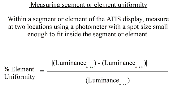
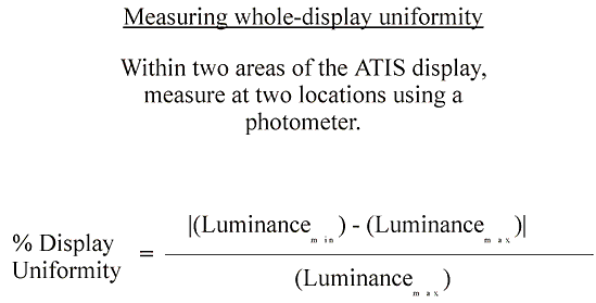
Introduction: Symbol luminance uniformity refers to the consistency of luminance values across a display.
(Equation 5)

(Equation 6)

where:
Luminancemin = the smaller luminance value
Luminancemax = the greater luminance value
COLOR CONTRAST
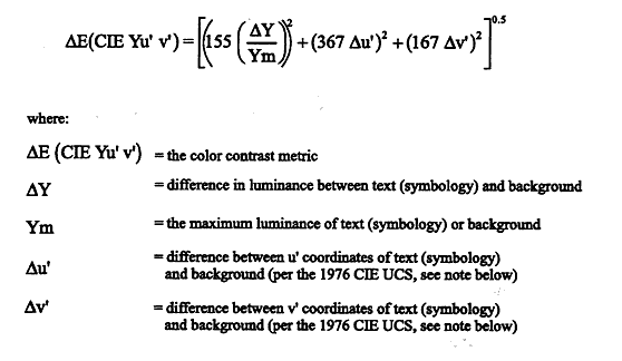
Introduction: Color contrast refers to the relationship between symbol and background associated with chromatic differences such as hue and saturation. Determining the amount of contrast provided to the driver becomes a more complex problem when the symbology and/or the background are colored.
(Equation 7)

MESSAGE STYLES
Introduction: Message style refers to the way in which information is given to the driver. The information can be presented in an advisory manner ("command style") or in more of a descriptive manner ("notification style"). Command style messages inform drivers of a situation and suggest a particular action to take in response to that situation. Notification style messages simply inform drivers and allow them to determine the appropriate action on their own. Message style should be selected based on an evaluation of the criticality of the situation and the need to make a control action immediately.
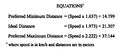
(Equation 8)
"Immediate" is defined as an inceident or condition which occurs within "X" meters of the vehicle's current position, where:
X = (Speed (in km/h) x 1.637) + 14.799
DESIGN OF HEAD–UP DISPLAYS FOR ATIS
Introduction: The automotive HUD is an electro–optical device that presents both static and dynamic symbology and/or graphics in the driver's forward FOV. Presenting navigation information to drivers through HUDs is possible due to recent developments in automotive design, electronic instrumentation, and optics.
(Equation 9)
The Luminance Control Function for an automotive HUD
Footlambert = [(P x Lmax0.33) + ((1–P) x (Lmin0.33))] (1 ) 0.33)
where:
P = the proportion of total control movement
Lmax = maximum luminance provided
Lmin = minimum luminance provided
TIMING OF AUDITORY NAVIGATION INFORMATION
Introduction: The timing of auditory navigation information refers to the time or distance at which ATIS should present an auditory instruction to the driver before an approaching navigation maneuver (e.g., a required turn).
(Equations 10, 11, and 12)

FHWA-RD-98-057
|
