Prefabricated Steel Bridge Systems: Final Report
3. Accelerated Construction: Minimum System Requirements
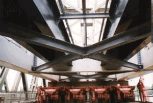
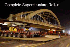
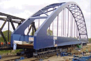
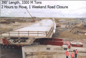
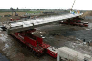
Many unique and innovative designs, construction methods, and erection techniques have been used throughout the world for bridge structures. State-of-the-art technology today has created record spans of every type of bridge structure, from movable bridges to cable-stayed and suspension bridges. Developments in heavy hauling (see Figure 3.1) and lifting equipment have opened up the possibility of prefabricating and erecting an entire bridge superstructure as one unit. Moving and lifting systems have the ability to remove, install, or relocate entire spans weighing thousands of tons. General examples of these innovative techniques are shown in Figure 3.2. An excellent summary of these innovative construction techniques is presented in "Prefabricated Bridge Elements and Systems in Japan and Europe; FHWA-PL-05-003, U.S. DOT, FHWA, March 2005".
Figure 3.1 Heavy Hauling and Lifting Equipment
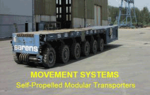
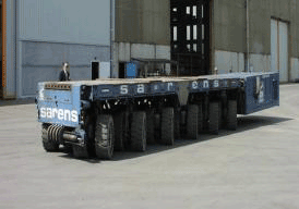
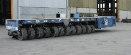
Figure 3.2 Innovative Construction Techniques
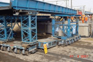
Unique prefabrication/preassembly can take place nearby an existing bridge and then floated to the construction site on barges as shown in Figure 3.3 (the George P. Coleman Bridge located in Yorktown, Virginia). This is the largest double-swing span bridge in the United States.
Figure 3.3: George P. Coleman Bridge
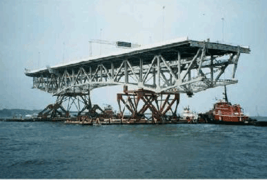
Source: http://www.aashtotig.org/ Credits: Virginia Department of Transportation
While these unique transportation and erection methods provide an excellent way of accelerating construction, the thrust of the research presented in this report is to develop new concepts with the ability to be fabricated, transported, and erected by conventional construction and transportation means and methods. This objective is clearly stated in the scope of services as follows: "The scope of this work will be limited to prefabricated systems for steel bridges to achieve project objectives with the effort necessary to identify and develop steel bridge concepts that have promise to improve the state-of-practice relative to details, materials and methods for increasing the speed of construction and service life of bridges ... and identify any existing problems hindering the wide use of these prefabricated systems ... and to determine the feasibility of further development and constructability including efficient and economical erection procedures."
It is believed that achieving this goal will help in the wide acceptance and embracing of the new concepts by the structural steel industry, steel fabricators, bridge designers, contractors and ownership agencies since utilization of these systems is not limited by the availability of specialized transportation and erection equipments.
3.1 Conventional Construction and Erection Techniques
Similar to the set of criteria used in developing the Bailey bridge system, a set of performance parameters needs to be developed for any new bridge concept. A discussion of these parameters and their importance is presented in this section.
3.1.1 Configurations of Modular Systems
Although prefabricated steel bridges have evolved since their inception in the 1930's and have become adaptable to various design criteria, they are not nearly as adaptable as traditional bridge designs.
In order to become competitive with "in-place construction" of steel and/or concrete bridges, prefabricated systems must be aesthetically acceptable and provide benefits such as:
- Cost effectiveness / standardization
- Faster installation
- Design flexibility
- Easy handling and transportation of components
- Reduced superstructure depth
- Greater durability
- Reduced maintenance
3.1.2 Cost Effectiveness / Standardization
Initial high cost of the systems compared to other traditional alternatives could present a problem to establishing demand for any new innovative system. In most cases, the fabricator/contractor is hesitant to invest substantial capital in the equipments necessary for the production of new bridge systems not knowing future demand and whether these equipments will be used in any other bridge projects. Therefore, the tendency is to expense the cost of the equipments over the project under consideration instead of multiple projects resulting in substantially increased costs.
To insure cost effectiveness any new system must be developed with details that can easily be standardized allowing multi purpose usage of manufacturing equipments. With multi usage, standardization will bring costs down over time, and make a prefabricated bridge system economically competitive with traditional methods of bridge construction. The economics of a design should consider not only the initial costs, but also the indirect costs and benefits to the public associated with the reduction in construction time and site impact.
The benefits of reduced construction time and daily user costs are paramount in determining the desirability of prefabricated steel bridge systems. In most cases, ownership agencies must be cognizant of this fact when selecting bridge structure types to be considered for specific locations.
3.1.3 Conventional Fabrication Methods
For structural steel rolled shapes and fabricated plate girders, the preferred methods of fabrication are welding in the Fabricating Plant and/or high-strength bolting in the Field. Welding at the bridge site is generally not preferred due to the environmental control necessary to produce acceptable weld quality and the difficulty in performing non destructive testing of welds. However, on site welding has been used routinely and successfully by Texas DOT and other state DOTs.
The American Institute of Steel Construction (AISC) has excellent references available for selecting steel rolled shapes and steel plate dimensions leading to economical fabrication. For example, it is more economical to use constant width flange plates and vary the plate thickness as required for optimum design and detailing. This is due to less labor involved in cutting standard mill plates to individual plates for girder fabrication.
3.1.4 Construction Issues Associated With Modular Bridge Systems
Given the time constraints during a bridge rehabilitation/replacement project or in cases of an emergency, it is necessary for the bridge to be constructed as fast as possible. Safety of the construction workers and the public is generally enhanced with the shorter construction time. In some instances, the use of modular units have can reduce the construction time significantly which is imperative when the user cost of a facility is high.
The ease and speed of construction of a prefabricated bridge system is paramount to its acceptance as a viable system for general use. Therefore, the criteria used in this study to formulate the process of selecting systems for further evaluation place a high emphasis on these factors.
Connections of the modular units are important elements for accelerated bridge construction, since it is envisioned that the new system will consist of either an entirely prefabricated bridge system manufactured off site, transported and erected in place or modular bridge units which can be easily assembled and connected together to form the bridge system.
Number of joints (longitudinal vs. transverse)
A major design and detailing factor in the modular units system is the development of proper joint details that require minimum time for installation and are capable of providing the desired long term durability. There are various jointing techniques that have been used; however, talking to a bridge engineer one most often hears "The ideal joint is no joint". Joints are prone to deterioration and are considered the weakest link in any structure, thereby reducing their effectiveness and long term performance. Freeze and thaw along with deicing salt are some of the parameters affecting joint performance. Therefore, minimizing the number of joints in a modular bridge system and using appropriate joint material are important factors that require careful examination.
The number of longitudinal joints versus transverse joints In a particular span is a function of the configuration of the main components of a particular modular system and the span length. Typically, systems that have short span lengths have no transverse joints and no or a few number of longitudinal joints depending on the width of the span. In contrast, systems that have greater span lengths typically have few or no longitudinal joints and more transverse joints.
The number of joints and the type of joint detail is crucial to both the speed of construction and to the overall durability of the final structure. Therefore, of the various criteria used for selecting the systems to be developed further, a total of 20% of the criteria importance is place on joint quantity, type and details.
Joint Details
As noted previously, minimizing the number of joints is desirable. However, for a modular bridge system, it is inherent that the resulting number of joints needed to construct the bridge will be greater than that in conventional cast-in-place concrete deck slab construction.
The ideal joint detail for a prefabricated modular system is that of a simple "shear key" configuration with the use of an epoxy, non-shrink grout to fill the joints. The joints also may have a bolted connection or transverse post-tensioning. For systems such as the Railroad Flatbed modular system, the joint is of a width that requires the use of cast-in-place concrete due to the large volume required.
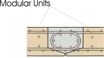
A typical deck slab longitudinal joint that has been used successfully is shown in Figure 3.4.
Figure 3.4 A Typical Joint
The performance of all joints in the final bridge structure is crucial to durability and long term maintenance.
Continuity Details
Provision for using prefabricated steel modular systems as continuous bridges with superimposed dead loads and live load are possible, but it may not be cost-effective in regard to the advantages gained. Providing longitudinal continuity has many beneficial effects such as: i) increased structural stiffness, ii) slight reduction in structure depth, iii) reduction in transverse cracking in the deck and iv) reduction in the number of transverse joints over the supports.
However, the use of prefabricated deck systems inhibits the placement of the significant amount of reinforcing steel or post-tensioning necessary to resist negative moments from longitudinal continuity. Post-tensioning bars or tendons can be installed external to the girders and deck, similar to the new St. Simons Bridge approach spans in Brunswick, Georgia.
Providing full system continuity under dead load and live load could prove difficult and time consuming for the objective of accelerated construction. Providing continuity for live loads only has been used successfully for many years and therefore is recommended for the new system.
The issues of durability and maintenance are most affected by the addition of continuity details. The modular systems selected for further study will be fully evaluated for the use of continuity through the bridge deck to resist applied live loads.
Closure Joints Materials
As noted previously, the use of cast-in-place concrete should be kept to a minimum for accelerated construction methods due to placement, finishing and curing time. The ideal material for any closure joints is a non-shrink grout, possibly with the addition of a fine aggregate to increase volume.
Another option for large volume joints is the use of fast-setting magnesium-based proprietary concrete mixes. Polymer materials are also gaining popularity and could prove effective as the material of choice for joints.
The closure joint design and material are important issues that are currently being researched under NCHRP project 10-71 "Cast-in-Place Reinforced Concrete Connections for Precast Deck Systems". The knowledge gained from this recent research and past experience could be easily utilized to develop and test the joint details for the proposed bridge systems.
Riding Surface Preparation
To the traveling public, a bridge is only as good as the smoothness of the riding surface. This is also an important factor to durability and maintenance, as vibrations from an irregular surface can affect the structural steel components of a bridge.
Due to irregularities in the riding surface that can occur at longitudinal and transverse joint locations between modular components, it may be necessary to profilograph, or "plane", the deck surface after construction is complete. In recent years, many states have taken to using planed deck through diamond grinding the surfaces, and the availability of equipment and the cost is reasonable.
Utilizing Cast-In-Place Concrete
Cast-in-place concrete could be used efficiently providing that the new system is self contained, thereby eliminating the need for forming and shoring. There are many cases where a large portion of the concrete deck was replaced and the bridge opened for traffic within 48 hours. For this type of bridge system, polymer concrete can be used or the specified concrete must have a low water-to-cement ratio with as much rapid setting characteristic as possible. The most rapid setting mix would utilize Type III cement with rapid setting admixtures.
3.1.5 Transportation and Erection Issues
Transportation and erection (crane capacity) limitations could present challenges that need to be considered in the initial development process. These limitations could influence the maximum span lengths of the new bridge system and might necessitate breaking down the system into multiple smaller-size components. For example, precast elements up to 170 ft long has been transported successfully using ground transportation, however, the width that can be transported without special permit is generally limited to 8 ft. Anything wider than 8 ft. would require a special permit for transportation or can be transported by a barges, if feasible. It is anticipated that multiple concepts might be necessary in order to address span and width requirements. Reliable and quick methods for making connections between components will be an important part of the concept development.
The utilization of lightweight prefabricated elements could prove important in development and advancements of new innovative bridge systems. Optimizing the weight of these bridge systems through design and/or the use of new lighter and durable materials will allow the transportation and erection of larger and longer bridges. High performance materials that are lightweight and durable are most suited for prefabrication in large sizes.
The original Bailey bridge design had the requirement of being transportable in a three-ton military truck. Today, the panels can be nested in standard storage containers.
Span Lengths
One of the main challenges facing designers of prefabricated steel bridges is the necessity for permanent, long lasting bridges particularly those with long spans. Today, with the increases in technology of temporary structures, the maximum length attainable is approximately 450 feet clear spans depending on traffic loads and site conditions. However, for permanent bridges, spans up to the range of 140 to 160 feet are the realistic limit due to transportation weight limits. The span limitations for the systems selected for further development will be determined by conventional construction and transportation means and methods. The maximum length of spans will be determined by transportation weight limits. The type of material and unit configuration will determine the weight, therefore the maximum attainable span length.
Maximum Unit Width
Generally, the maximum width of individual modular components will be predicated upon using conventional transportation vehicles and widths that do not require special hauling permits from government authorities. However, depending on the location of the bridge, larger systems can be transported on a barge through waterways or under special hauling permits from government authorities.
The intent of this study, for all systems considered, is to develop the greatest maximum width in order to:
- Reduce the number of longitudinal joints
- Provide optimum spacing and the number of longitudinal girders per unit
- Reduce the number of components required for the total bridge width
- Improve the riding surface of the bridge
System Unit Weight
The system unit weight will be dependent on a number of factors such as width, span length, precast deck-on-girders versus separate precast units. The maximum weight of an individual component will be predicated upon the allowable transported load without special hauling permits from government agencies. Utilization of lightweight concrete and system optimization will be important in reducing the unit weight, hence increasing the maximum span length.
Crane Capacity
It is not expected that the capacity of cranes used during erection, nor of "travel lift" handling equipment in a fabricating plant, will affect the design of the systems selected for final development. However, other considerations such as site accessibility, ease of erection and limited headroom conditions could influence the final selection. These considerations will be confirmed or otherwise addressed by presentation and discussion of the final systems developed working with several fabricators and contracting firms.
3.1.6 Design Loads and 75-Year Service Life
Design criteria for this project are in accordance with the AASHTO LRFD Bridge Design Specifications. Therefore, the "service life" as defined in Section 1.2 of the code is: "Design Life - Period of time on which the statistical derivation of transient loads is based: 75 years for these Specifications." Any new bridge system should meet this minimum design life requirement for wide acceptance and implementation. The design vehicle is the HL-93.
Fatigue Resistance
Any new system should meet the minimum fatigue requirements as specified in the AASHTO LRFD Bridge Design Specifications. All systems developed for this project shall be designed and optimized to meet the minimum code requirements.
Seismic Performance
The seismic performance of individual systems should not be a priority factor in the selection of the final systems to be developed in this project. The purpose of the project is to identify and develop steel bridge concepts that have promise to improve the state-of-practice relative to details, materials and methods for increasing the speed of construction and service life of bridges ... and identify any existing problems hindering the wide use of these prefabricated systems ... and to determine the feasibility of further development and constructability including efficient and economical erection procedures."
To develop the final selected systems based on seismic performance being of highest priority would be to limit the wide use of the systems. The selected systems may be modified and strengthened if necessary for extreme seismic locations.
3.1.7 Future Maintenance
There are three important aspects to consider in the development of a new bridge system with regard to future maintenance and durability:
- Access (i.e., Inspectable)
- Inspection effort
- Durability (High performance materials (steel, coatings, etc.))
Maintainability is a critical and important aspect of selecting the systems for further development. The system configuration of components determines physical access and required inspection efforts. Long term durability is another important aspect of bridge maintenance that should be considered. Better design details and utilizing high performance materials such as high performance steel, polymer concrete, and specialized coatings in the manufacturing process could significantly increase durability of the system. These design and material enhancements might increase the initial system cost but it will certainly result in reducing future maintenance costs and traffic interruptions.

