U.S. Department of Transportation
Federal Highway Administration
1200 New Jersey Avenue, SE
Washington, DC 20590
202-366-4000
Federal Highway Administration Research and Technology
Coordinating, Developing, and Delivering Highway Transportation Innovations
 |
| This report is an archived publication and may contain dated technical, contact, and link information |
|
Publication Number: FHWA-RD-02-082 Date: August 2006 |
| Joint | Shoulder Lane Observations | Travel Lane Observations |
|---|---|---|
| Start of C1 | Joint is intact and well sealed. Cracking perpendicular to the joint along entire joint. No nearby transverse cracks. Twenty-one cracks along joint. Spalling at joint with shoulder. | Four spalls, 1 large in right wheelpath. All patched, but subsequent loss of material in center patch. More PCC spalling pieces. |
| C1-T1 | Joint intact and well sealed. Perpendicular cracks intercepting full width of the joint. Transverse cracks in outer 3.05 m at 0.305 m from the joint. | Heavy spalls in 3.05 m of lane, all patched with asphalt. Concrete is lost in outer 0.61 m in two separate spalls. All joints spalled. AC patch 0.92 m by 3.05 m. |
| T1-T2 | Joint intact and well sealed. Intersecting cracks perpendicular to the joint at 0.305 m on center along the whole joint. Twenty-four cracks along joint. | Heavy loss of material over 10 feet of joint, all patched with asphalt. Patch largest at joint with shoulder. AC patch 0.61 m x 3.05 m. Also patch at shoulder joint 0.305 m x 3.05 m. |
| T2-C2 | Joint intact and well sealed. Cracks perpendicular to and intersecting the whole joint. No nearby transverse cracks. Twenty-one cracks along joint. | Unpatched small (less than .305 m from joint) spalls over 1.83 m of joint. Spalling also along longitudinal shoulder joint. |
| C2-C3 | Joint intact and well sealed. Cracks perpendicular to and intersecting the joint along 0.92 m of joint. Light cracking over remainder of joint. Scattered nearby transverse cracks. Sixteen cracks along joint. | Spalls over 3.05 m of joint, all patched with asphalt. Patch widest at longitudinal joint. |
| C3-C4 | Joint intact and well sealed. .305 m spall 50.8 mm wide near longitudinal joint. Cracks perpendicular to joint stop .305 m from joint, with cracks extending to joint all of joint. Light cracking, no staining. Seventeen cracks along joint. | Spall along 2.44 m of joint, all patched with asphalt. Patch approximately 0.305 m wide on either side of joint, with wider patch (0.92 m x 0.92 m) at longitudinal joint. Some new PCC spalling. |
| C4-T3 | Joint intact and well sealed. Very light perpendicular cracking along joint. No nearby transverse cracking. Ten cracks along joint. | Right wheelpath patch over 0.92 m x 0.305 m area, 0.61 m x 0.61 m patch in center with some concrete loss around edge of patch. Transverse crack 0.92 m from joint with 0.305 m x 0.305 m spall. |
| T3-T4 | Joint intact and well sealed. Cracking along joint. Eleven cracks along joint. | Small spall 20.3 cm x 20.3 cm at longitudinal joint. |
| T4-C5 | Joint intact and well sealed. Very light perpendicular cracking at joint with 15.2 cm corner spall in C5. All cracks narrow with brown staining. Fourteen cracks along joint. | 20.3 to 30.5-cm wide asphalt patch along 0.92 m of C5 section. New PCC spalling. |
| C5-end | Joint intact and well sealed. Light widely-spaced cracking perpendicular to joint and along entire joint. Thirteen cracks along joint. | Small .305 m x .305 m patch near longitudinal joint at transverse joint. |
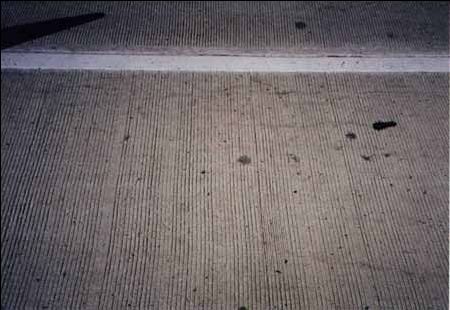
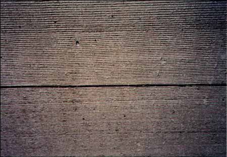
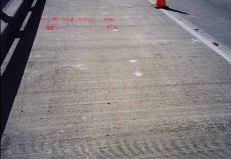
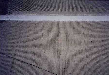
Figure B1. Photographs of typical area of each section (Newark, DE).
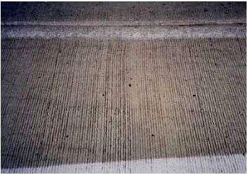
(a) Control section 1 (C1)
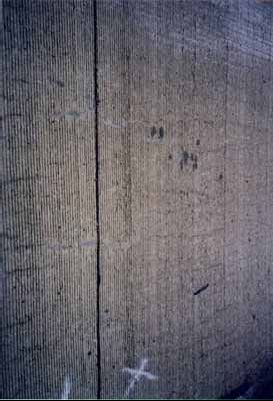
(b) Test section 1 (TS1)
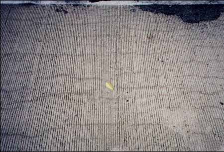
(c) Test section 2 (TS2)
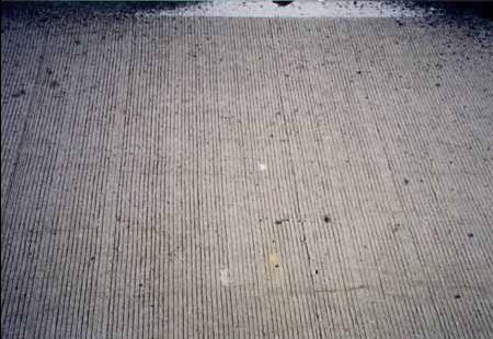
(d) Control section 2 (C2)
(e) Control section 3 (C3)
(f) Control section 4 (C4)
(g) Test section 3 (TS3)

(h) Test section 4 (TS4)
(i) Control section 5 (C5)
Sections from each of the cores were cut and lapped. These sections were then soaked overnight, dried, and the entire lapped surface was traversed under a stereo microscope. The lapped surface was divided into five or more traverses and examined at magnifications of 10 to 30 times. All instances of cracks, alkali-silica gel, and deteriorated or reacted aggregate particles were counted.
Core 97C1A: the core is poorly and nonuniformly air-entrained, with an estimated air content of 4.5 percent. Distress to the wearing surface appears limited to small popouts over fine aggregate particles. The core is moderately severely distressed. One major crack bisects the core into top and bottom halves. Additionally, 40 microcracks and 27 instances of alkali-silica gel were counted. Three coarse aggregate particles appear to have reacted slightly; 24 fine aggregate particles were distressed or had reacted.
Core 97C5A: the core is poorly and nonuniformly air-entrained with an estimated air content of 5 percent. Distress to the wearing surface appears limited to small popouts over fine aggregate particles. The core is moderately severely distressed. One major crack bisects the core into top and bottom halves. Thirty-four other microcracks were counted, and 31 occurrences of alkalisilica gel. Three coarse aggregate particles appear to have reacted slightly. Twenty-seven fine aggregate particles are distressed or have reacted.
Core 97T51A: the core is poorly and nonuniformly air-entrained with an estimated air content of 4 percent. Distress to the wearing surface appears limited to small popouts over fine aggregate particles. The core is severely distressed. Eighty-seven cracks were counted, along with 42 occurrences of alkali-silica gel. Thirty-one reacted or distressed fine aggregate particles were counted.
Core 97T52B: the core is marginally air-entrained with an estimated air content of 5 percent. Distress to the wearing surface appears limited to small popouts over fine aggregate particles. The core is moderately severely distressed. Forty-three cracks and 33 instances of alkali-silica gel were detected. Twenty-nine reacted or distressed fine aggregate particles were detected.
Core 97T53B: the core is well air-entrained with an estimated air content of 6.5 percent. Distress to the wearing surface appears limited to small popouts over fine aggregate particles. Distress is relatively minor. Seventeen cracks were counted, and 25 instances of alkali-silica gel. Twentythree fine aggregate particles had reacted or were distressed.
Core 97T54B: the core is poorly air-entrained with an estimated air content of 3.5 percent. Distress to the wearing surface is apparently limited to small popouts over fine aggregate particles. Distress is minor. Eight cracks and 13 occurrences of alkali-silica gel were counted. Thirty-one fine aggregate particles had reacted or were distressed.
Distress is relatively severe in all but the last two cores. We do not have sufficient information to interpret the possible reason, since all were treated with lithium compounds, but we have not been told what differences there were.
Sections from each of the cores were cut and lapped. These sections were then soaked overnight, dried, and the entire lapped surface was traversed under a stereo microscope. Each lapped surface was divided into five or more traverses areas and examined at magnifications of 10 to 30 times. All instances of cracks, alkali-silica gel, and deteriorated or reacted aggregate particles were counted.
Core 98-C1-A: the core is severely distressed. The wearing surface is grooved and worn. Fine aggregate particles on the wearing surface are frequently exposed, occasionally in popouts. Seventy-seven microcracks, one large crack, and 49 instances of alkali-silica gel were counted. Thirty-nine reacted or distressed fine aggregate particles were counted. The core is air-entrained with an estimated air content of 6.5 percent.
Core 98-C5-B: the core is severely distressed. The wearing surface is grooved and worn. Fine aggregate particles on the wearing surface are frequently exposed, occasionally in popouts. Fiftyseven microcracks and 79 instances of alkali-silica gel were counted. Forty-two fine aggregate particles showed evidence of distress or reaction. The core is air-entrained with an estimated air content of 6 percent.
Core 98-TS1-A: the core is severely distressed. The wearing surface is grooved and worn, with fine and coarse aggregate particles partially exposed. Fine aggregate particles are occasionally exposed in popouts. Two major cracks and fifty microcracks were counted. Sixty-one instances of alkali-silica gel and 38 reacted or distressed fine aggregate particles were counted. The core is air-entrained with an estimated air content of 5.5 percent.
Core 98-TS-2B: the core is severely distressed. The grooved wearing surface is severely worn, exposing fine and coarse aggregate particles. Fine aggregate particles are frequently exposed in popouts. One major and 64 microcracks were detected. Fifty-eight instances of alkali-silica gel and 23 reacted or distressed fine aggregate particles were counted. The core is air-entrained with an estimated air content of 7.5 percent.
Core 98-TS-3A: the core is slightly to moderately distressed. The grooved wearing surface is moderately worn with both fine and coarse aggregate particles exposed on it, but with few identifiable popouts. Twenty-five microcracks and 43 instances of alkali-silica gel were counted. Fifteen fine aggregate particles had reacted or showed distress. The core is highly air entrained with an estimated air content of 8.5 percent.
Core 98-TS-4B: the core is slightly distressed. The grooved wearing surface is severely worn with no other distinct evidence of distress. Fourteen microcracks and 44 instances of alkali-silica gel were detected. Fifteen fine aggregate particles showed evidence of distress or reaction. The core is air entrained with an estimated air content of 7.5 percent.
| Type | Identification code | Unit | 11/29/94 | 11/28/95 | 11/21/96 | 12/9/97 | 10/22/98 |
|---|---|---|---|---|---|---|---|
| Corner breaks | 1L | No. | 0 | 0 | 0 | 0 | 0 |
| 1M | No. | 0 | 0 | 0 | 0 | 0 | |
| 1H | No. | 0 | 0 | 0 | 0 | 0 | |
| Durability cracking | 2L | No. | 0 | 0 | 0 | 0 | 0 |
| 2L | M2 | 0 | 0 | 0 | 0 | 0 | |
| 2M | No. | 0 | 0 | 0 | 0 | 0 | |
| 2M | M2 | 0 | 0 | 0 | 0 | 0 | |
| 2H | No. | 0 | 0 | 0 | 0 | 0 | |
| 2H | M2 | 0 | 0 | 0 | 0 | 0 | |
| Longitudinal cracking | 3L | m | 0 | 0 | 0 | 0 | 0 |
| 3L (sealed) | m | 0 | 0 | 0 | 0 | 0 | |
| 3M | m | 0 | 0 | 0 | 0 | 0 | |
| 3M (sealed) | m | 0 | 0 | 0 | 0 | 0 | |
| 3H | m | 0 | 0 | 0 | 0 | 0 | |
| 3H (sealed) | m | 0 | 0 | 0 | 0 | 0 | |
| Transverse cracking | 4L | No. | 1 | 1 | 1 | 1 | 1 |
| 4L | m | 3.4 | 3.4 | 3.4 | 3.4 | 3.4 | |
| 4L (sealed) | m | 0 | 0 | 0 | 0 | 0 | |
| 4M | No. | 0 | 0 | 0 | 0 | 0 | |
| 4M | m | 0 | 0 | 0 | 0 | 0 | |
| 4M (sealed) | m | 0 | 0 | 0 | 0 | 0 | |
| 4H | No. | 0 | 0 | 0 | 0 | 0 | |
| 4H | m | 0 | 0 | 0 | 0 | 0 | |
| 4H (sealed) | m | 0 | 0 | 0 | 0 | 0 | |
| Transverse joint seal damage | Sealed | Y/n | Y | Y | Y | Y | Y |
| 5aL | No. | 1 | 1 | 1 | 1 | 1 | |
| 5aM | No. | 0 | 0 | 0 | 0 | 0 | |
| 5aH | No. | 0 | 0 | 0 | 0 | 0 | |
| Longitudinal joint seal damage | No.sealed | No. | 2 | 2 | 2 | 2 | 0 |
| 5b | m | 12.2 | 12.2 | 12.2 | 12.2 | 12.2 | |
| Spalling of longitudinal joints | 6L | m | 0 | 0 | 0 | 0 | 0 |
| 6M | m | 0 | 0 | 0 | 0 | 0 | |
| 6H | m | 0 | 0 | 0 | 0 | 0 | |
| Spalling of transverse joints | 7L | no. | 0 | 1 | 1 | 1 | 1 |
| 7L (length) | m | 0 | 0.2 | 1.8 | 2 | 2 | |
| 7M | no. | 0 | 0 | 0 | 0 | 0 | |
| 7M (length) | m | 0 | 0 | 0 | 0 | 0 | |
| 7H | no. | 0 | 0 | 0 | 0 | 0 | |
| 7H (length) | m | 0 | 0 | 0 | 0 | 0 | |
| Map cracking | 8a | no. | 1 | 7 | 1 | 1 | 1 |
| 8a | m2 | 11.5 | 23.2 | 26.8 | 27.8 | 29.7 | |
| Scaling | 8b | no. | 0 | 0 | 0 | 0 | 0 |
| 8b | m2 | 0 | 0 | 0 | 0 | 0 | |
| Polished aggregate | 9 | m2 | 0 | 0 | 0 | 0 | 0 |
| Popouts | 10 | no./m2 | 0 | 0 | 0 | 0 | 0 |
| Blowups | 11 | no. | 0 | 0 | 0 | 0 | 0 |
| Faulting | 12 | - | - | - | - | - | - |
| Lane-shoulder dropoff | 13 | - | - | - | - | - | - |
| Lane-shoulder separation | 14 | - | - | - | - | - | - |
| Flexible patch deterioration | 15fL | no. | 0 | 0 | 0 | 0 | 0 |
| 15fL | m2 | 0 | 0 | 0 | 0 | 0 | |
| 15fM | no. | 0 | 0 | 0 | 0 | 0 | |
| 15fM | m2 | 0 | 0 | 0 | 0 | 0 | |
| 15fH | no. | 0 | 0 | 0 | 0 | 0 | |
| 15fH | m2 | 0 | 0 | 0 | 0 | 0 | |
| Rigid patch deterioration | 15rL | no. | 0 | 0 | 0 | 0 | 0 |
| 15rL | m2 | 0 | 0 | 0 | 0 | 0 | |
| 15rM | no. | 0 | 0 | 0 | 0 | 0 | |
| 15rM | m2 | 0 | 0 | 0 | 0 | 0 | |
| 15rH | no. | 0 | 0 | 0 | 0 | 0 | |
| 15rH | m2 | 0 | 0 | 0 | 0 | 0 | |
| Bleeding and pumping | 16 | no. | 0 | 0 | 0 | 0 | 0 |
| 16 | m | 0 | 0 | 0 | 0 | 0 | |
| Other | 17 | - | - | - | - | - | - |
| Type | Identification code | Unit | 11/29/94 | 11/28/95 | 11/21/96 | 12/9/97 | 10/22/98 |
|---|---|---|---|---|---|---|---|
| Corner breaks | 1L | no. | 0 | 0 | 0 | 0 | 0 |
| 1M | no. | 0 | 0 | 0 | 0 | 0 | |
| 1H | no. | 0 | 0 | 0 | 0 | 0 | |
| Durability cracking | 2L | no. | 0 | 0 | 0 | 0 | 0 |
| 2L | m2 | 0 | 0 | 0 | 0 | 0 | |
| 2M | no. | 0 | 0 | 0 | 0 | 0 | |
| 2M | m2 | 0 | 0 | 0 | 0 | 0 | |
| 2H | no. | 0 | 0 | 0 | 0 | 0 | |
| 2H | m2 | 0 | 0 | 0 | 0 | 0 | |
| Longitudinal cracking | 3L | m | 0 | 0 | 0 | 0 | 0 |
| 3L (sealed) | m | 0 | 0 | 0 | 0 | 0 | |
| 3M | m | 0 | 0 | 0 | 0 | 0 | |
| 3M (sealed) | m | 0 | 0 | 0 | 0 | 0 | |
| 3H | m | 0 | 0 | 0 | 0 | 0 | |
| 3H (sealed) | m | 0 | 0 | 0 | 0 | 0 | |
| Transverse cracking | 4L | no. | 0 | 0 | 0 | 0 | 0 |
| 4L | m | 0 | 0 | 0 | 0 | 0 | |
| 4L (sealed) | m | 0 | 0 | 0 | 0 | 0 | |
| 4M | no. | 0 | 0 | 0 | 0 | 0 | |
| 4M | m | 0 | 0 | 0 | 0 | 0 | |
| 4M (sealed) | m | 0 | 0 | 0 | 0 | 0 | |
| 4H | no. | 0 | 0 | 0 | 0 | 0 | |
| 4H | m | 0 | 0 | 0 | 0 | 0 | |
| 4H (sealed) | m | 0 | 0 | 0 | 0 | 0 | |
| Transverse joint seal damage | Sealed | y/n | Y | Y | Y | Y | Y |
| 5aL | no. | 1 | 1 | 1 | 1 | 1 | |
| 5aM | no. | 0 | 0 | 0 | 0 | 0 | |
| 5aH | no. | 0 | 0 | 0 | 0 | 0 | |
| Longitudinal joint seal damage | No. sealed | no. | 2 | 2 | 2 | 2 | 2 |
| 5b | m | 12.2 | 12.2 | 12.2 | 12.2 | 12.2 | |
| Spalling of longitudinal joints | 6L | m | 1.5 | 0.5 | 1.8 | 1.8 | 1.8 |
| 6M | m | 0 | 0 | 0 | 0 | 0 | |
| 6H | m | 0 | 0 | 0 | 0 | 0 | |
| Spalling of transverse joints | 7L | no. | 0 | 0 | 1 | 1 | 1 |
| 7L (length) | m | 0 | 0 | 2.1 | 3.4 | 3.4 | |
| 7M | no. | 0 | 0 | 0 | 0 | 0 | |
| 7M (length) | m | 0 | 0 | 0 | 0 | 0 | |
| 7H | no. | 0 | 0 | 0 | 0 | 0 | |
| 7H (length) | m | 0 | 0 | 0 | 0 | 0 | |
| Map cracking | 8a | no. | 1 | 1 | 1 | 1 | 1 |
| 8a | m2 | 11.8 | 21.8 | 28.3 | 29.1 | 31.4 | |
| Scaling | 8b | no. | 0 | 0 | 0 | 0 | 0 |
| 8b | m2 | 0 | 0 | 0 | 0 | 0 | |
| Polished aggregate | 9 | m2 | 0 | 0 | 0 | 0 | 0 |
| Popouts | 10 | no./m2 | 0 | 0 | 0 | 0 | 0 |
| Blowups | 11 | no. | 0 | 0 | 0 | 0 | 0 |
| Faulting | 12 | - | - | - | - | - | - |
| Lane-shoulder dropoff | 13 | - | - | - | - | - | - |
| Lane-shoulder separation | 14 | - | - | - | - | - | - |
| Flexible patch deterioration | 15fL | no. | 0 | 0 | 0 | 0 | 0 |
| 15fL | m2 | 0 | 0 | 0 | 0 | 0 | |
| 15fM | no. | 0 | 0 | 0 | 0 | 0 | |
| 15fM | m2 | 0 | 0 | 0 | 0 | 0 | |
| 15fH | no. | 0 | 0 | 0 | 0 | 0 | |
| 15fH | m2 | 0 | 0 | 0 | 0 | 0 | |
| Rigid patch deterioration | 15rL | no. | 0 | 0 | 0 | 0 | 0 |
| 15rL | m2 | 0 | 0 | 0 | 0 | 0 | |
| 15rM | no. | 0 | 0 | 0 | 0 | 0 | |
| 15rM | m2 | 0 | 0 | 0 | 0 | 0 | |
| 15rH | no. | 0 | 0 | 0 | 0 | 0 | |
| 15rH | m2 | 0 | 0 | 0 | 0 | 0 | |
| Bleeding and pumping | 16 | no. | 0 | 0 | 0 | 0 | 0 |
| 16 | m | 0 | 0 | 0 | 0 | 0 | |
| Other | 17 | - | - | - | - | - | - |
| Type | Identification code | Unit | 11/29/94 | 11/28/95 | 12/21/96 | 12/9/97 | 10/22/98 |
|---|---|---|---|---|---|---|---|
| Corner breaks | 1L | no. | 0 | 0 | 0 | 0 | 0 |
| 1M | no. | 0 | 0 | 0 | 0 | 0 | |
| 1H | no. | 0 | 0 | 0 | 0 | 0 | |
| Durability cracking | 2L | no. | 0 | 0 | 0 | 0 | 0 |
| 2L | m2 | 0 | 0 | 0 | 0 | 0 | |
| 2M | no. | 0 | 0 | 0 | 0 | 0 | |
| 2M | m2 | 0 | 0 | 0 | 0 | 0 | |
| 2H | no. | 0 | 0 | 0 | 0 | 0 | |
| 2H | m2 | 0 | 0 | 0 | 0 | 0 | |
| Longitudinal cracking | 3L | m | 0 | 0 | 0 | 0 | 0 |
| 3L (sealed) | m | 0 | 0 | 0 | 0 | 0 | |
| 3M | m | 0 | 0 | 0 | 0 | 0 | |
| 3M (sealed) | m | 0 | 0 | 0 | 0 | 0 | |
| 3H | m | 0 | 0 | 0 | 0 | 0 | |
| 3H (sealed) | m | 0 | 0 | 0 | 0 | 0 | |
| Transverse cracking | 4L | no. | 0 | 0 | 0 | 0 | 0 |
| 4L | m | 0 | 0 | 0 | 0 | 0 | |
| 4L (sealed) | m | 0 | 0 | 0 | 0 | 0 | |
| 4M | no. | 0 | 0 | 0 | 0 | 0 | |
| 4M | m | 0 | 0 | 0 | 0 | 0 | |
| 4M (sealed) | m | 0 | 0 | 0 | 0 | 0 | |
| 4H | no. | 0 | 0 | 0 | 0 | 0 | |
| 4H | m | 0 | 0 | 0 | 0 | 0 | |
| 4H (sealed) | m | 0 | 0 | 0 | 0 | 0 | |
| Transverse joint seal damage | Sealed | y/n | Y | Y | Y | Y | Y |
| 5aL | no. | 1 | 1 | 1 | 1 | 1 | |
| 5aM | no. | 0 | 0 | 0 | 0 | 0 | |
| 5aH | no. | 0 | 0 | 0 | 0 | 0 | |
| Longitudinal joint seal damage | No. sealed | no. | 2 | 2 | 2 | 2 | 2 |
| 5b | m | 12.2 | 12.2 | 12.2 | 12.2 | 12.2 | |
| Spalling of longitudinal joints | 6L | m | 0 | 1.5 | 1.5 | 1.5 | 1.5 |
| 6M | m | 2.5 | 0 | 0 | 0 | 0 | |
| 6H | m | 0 | 0 | 0 | 0 | 0 | |
| Spalling of transverse joints | 7L | no. | 1 | 1 | 1 | 1 | 1 |
| 7L (length) | m | 3.4 | 3.4 | 3.4 | 3.4 | 3.4 | |
| 7M | no. | 0 | 0 | 0 | 0 | 0 | |
| 7M (length) | m | 0 | 0 | 0 | 0 | 0 | |
| 7H | no. | 0 | 0 | 0 | 0 | 0 | |
| 7H (length) | m | 0 | 0 | 0 | 0 | 0 | |
| Map cracking | 8a | no. | 1 | 1 | 1 | 1 | 1 |
| 8a | m2 | 8 | 14.9 | 25.3 | 25.3 | 26 | |
| Scaling | 8b | no. | 0 | 0 | 0 | 0 | 0 |
| 8b | m2 | 0 | 0 | 0 | 0 | 0 | |
| Polished aggregate | 9 | m2 | 0 | 0 | 0 | 0 | 0 |
| Popouts | 10 | no./m2 | 0 | 0 | 0 | 0 | 0 |
| Blowups | 11 | no. | 0 | 0 | 0 | 0 | 0 |
| Faulting | 12 | - | - | - | - | - | - |
| Lane-shoulder dropoff | 13 | - | - | - | - | - | - |
| Lane-shoulder separation | 14 | - | - | - | - | - | - |
| Flexible patch deterioration | 15fL | no. | 0 | 0 | 0 | 0 | 0 |
| 15fL | m2 | 0 | 0 | 0 | 0 | 0 | |
| 15fM | no. | 0 | 0 | 0 | 0 | 0 | |
| 15fM | m2 | 0 | 0 | 0 | 0 | 0 | |
| 15fH | no. | 0 | 0 | 0 | 0 | 0 | |
| 15fH | m2 | 0 | 0 | 0 | 0 | 0 | |
| Rigid patch deterioration | 15rL | no. | 0 | 0 | 0 | 0 | 0 |
| 15rL | m2 | 0 | 0 | 0 | 0 | 0 | |
| 15rM | no. | 0 | 0 | 0 | 0 | 0 | |
| 15rM | m2 | 0 | 0 | 0 | 0 | 0 | |
| 15rH | no. | 0 | 0 | 0 | 0 | 0 | |
| 15rH | m2 | 0 | 0 | 0 | 0 | 0 | |
| Bleeding and pumping | 16 | no. | 0 | 0 | 0 | 0 | 0 |
| 16 | m | 0 | 0 | 0 | 0 | 0 | |
| Other | 17 | - | - | - | - | - | - |
| Type | Identification code | Unit | 11/29/94 | 11/28/95 | 12/21/96 | 12/9/97 | 10/22/98 |
|---|---|---|---|---|---|---|---|
| Corner breaks | 1L | no. | 0 | 0 | 0 | 0 | 0 |
| 1M | no. | 0 | 0 | 0 | 0 | 0 | |
| 1H | no. | 0 | 0 | 0 | 0 | 0 | |
| Durability cracking | 2L | no. | 0 | 0 | 0 | 0 | 0 |
| 2L | m2 | 0 | 0 | 0 | 0 | 0 | |
| 2M | no. | 0 | 0 | 0 | 0 | 0 | |
| 2M | m2 | 0 | 0 | 0 | 0 | 0 | |
| 2H | no. | 0 | 0 | 0 | 0 | 0 | |
| 2H | m2 | 0 | 0 | 0 | 0 | 0 | |
| Longitudinal cracking | 3L | m | 0 | 0 | 0 | 0 | 0 |
| 3L (sealed) | m | 0 | 0 | 0 | 0 | 0 | |
| 3M | m | 0 | 0 | 0 | 0 | 0 | |
| 3M (sealed) | m | 0 | 0 | 0 | 0 | 0 | |
| 3H | m | 0 | 0 | 0 | 0 | 0 | |
| 3H (sealed) | m | 0 | 0 | 0 | 0 | 0 | |
| Transverse cracking | 4L | no. | 0 | 0 | 0 | 0 | 0 |
| 4L | m | 0 | 0 | 0 | 0 | 0 | |
| 4L (sealed) | m | 0 | 0 | 0 | 0 | 0 | |
| 4M | no. | 0 | 0 | 0 | 0 | 0 | |
| 4M | m | 0 | 0 | 0 | 0 | 0 | |
| 4M (sealed) | m | 0 | 0 | 0 | 0 | 0 | |
| 4H | no. | 0 | 0 | 0 | 0 | 0 | |
| 4H | m | 0 | 0 | 0 | 0 | 0 | |
| 4H (sealed) | m | 0 | 0 | 0 | 0 | 0 | |
| Transverse joint seal damage | Sealed | y/n | Y | Y | Y | Y | Y |
| 5aL | no. | 1 | 1 | 1 | 1 | 1 | |
| 5aM | no. | 0 | 0 | 0 | 0 | 0 | |
| 5aH | no. | 0 | 0 | 0 | 0 | 0 | |
| Longitudinal joint seal damage | No. sealed | no. | 2 | 2 | 2 | 2 | 2 |
| 5b | m | 12.2 | 12.2 | 12.2 | 12.2 | 12.2 | |
| Spalling of longitudinal joints | 6L | m | 0 | 0 | 0 | 0 | 0 |
| 6M | m | 0 | 0 | 0 | 0 | 0 | |
| 6H | m | 0 | 0 | 0 | 0 | 0 | |
| Spalling of transverse joints | 7L | no. | 0 | 0 | 1 | 1 | 1 |
| 7L (length) | m | 0 | 0 | 1.2 | 2.1 | 2.1 | |
| 7M | no. | 0 | 0 | 0 | 0 | 0 | |
| 7M (length) | m | 0 | 0 | 0 | 0 | 0 | |
| 7H | no. | 0 | 0 | 0 | 0 | 0 | |
| 7H (length) | m | 0 | 0 | 0 | 0 | 0 | |
| Map cracking | 8a | no. | 1 | 1 | 1 | 1 | 1 |
| 8a | m2 | 6 | 11.1 | 13.9 | 14.9 | 26 | |
| Scaling | 8b | no. | 0 | 0 | 0 | 0 | 0 |
| 8b | m2 | 0 | 0 | 0 | 0 | 0 | |
| Polished aggregate | 9 | m2 | 0 | 0 | 0 | 0 | 0 |
| Popouts | 10 | no./m2 | 0 | 0 | 0 | 0 | 0 |
| Blowups | 11 | no. | 0 | 0 | 0 | 0 | 0 |
| Faulting | 12 | - | - | - | - | - | - |
| Lane-shoulder dropoff | 13 | - | - | - | - | - | - |
| Lane-shoulder separation | 14 | - | - | - | - | - | - |
| Flexible patch deterioration | 15fL | no. | 0 | 0 | 0 | 0 | 0 |
| 15fL | m2 | 0 | 0 | 0 | 0 | 0 | |
| 15fM | no. | 0 | 0 | 0 | 0 | 0 | |
| 15fM | m2 | 0 | 0 | 0 | 0 | 0 | |
| 15fH | no. | 0 | 0 | 0 | 0 | 0 | |
| 15fH | m2 | 0 | 0 | 0 | 0 | 0 | |
| Rigid patch deterioration | 15rL | no. | 0 | 0 | 0 | 0 | 0 |
| 15rL | m2 | 0 | 0 | 0 | 0 | 0 | |
| 15rM | no. | 0 | 0 | 0 | 0 | 0 | |
| 15rM | m2 | 0 | 0 | 0 | 0 | 0 | |
| 15rH | no. | 0 | 0 | 0 | 0 | 0 | |
| 15rH | m2 | 0 | 0 | 0 | 0 | 0 | |
| Bleeding and pumping | 16 | no. | 0 | 0 | 0 | 0 | 0 |
| 16 | m | 0 | 0 | 0 | 0 | 0 | |
| Other | 17 | - | - | - | - | - | - |
| Type | Identification code | Unit | 11/29/94 | 11/28/95 | 12/21/96 | 12/9/97 | 10/22/98 |
|---|---|---|---|---|---|---|---|
| Corner breaks | 1L | no. | 0 | 0 | 0 | 0 | 0 |
| 1M | no. | 0 | 0 | 0 | 0 | 0 | |
| 1H | no. | 0 | 0 | 0 | 0 | 0 | |
| Durability cracking | 2L | no. | 0 | 0 | 0 | 0 | 0 |
| 2L | m2 | 0 | 0 | 0 | 0 | 0 | |
| 2M | no. | 0 | 0 | 0 | 0 | 0 | |
| 2M | m2 | 0 | 0 | 0 | 0 | 0 | |
| 2H | no. | 0 | 0 | 0 | 0 | 0 | |
| 2H | m2 | 0 | 0 | 0 | 0 | 0 | |
| Longitudinal cracking | 3L | m | 0 | 0 | 0 | 0 | 0 |
| 3L (sealed) | m | 0 | 0 | 0 | 0 | 0 | |
| 3M | m | 0 | 0 | 0 | 0 | 0 | |
| 3M (sealed) | m | 0 | 0 | 0 | 0 | 0 | |
| 3H | m | 0 | 0 | 0 | 0 | 0 | |
| 3H (sealed) | m | 0 | 0 | 0 | 0 | 0 | |
| Transverse cracking | 4L | no. | 1 | 1 | 1 | 1 | 1 |
| 4L | m | 2.4 | 2.4 | 2.4 | 2.4 | 2.4 | |
| 4L (sealed) | m | 0 | 0 | 0 | 0 | 0 | |
| 4M | no. | 0 | 0 | 0 | 0 | 0 | |
| 4M | m | 0 | 0 | 0 | 0 | 0 | |
| 4M (sealed) | m | 0 | 0 | 0 | 0 | 0 | |
| 4H | no. | 0 | 0 | 0 | 0 | 0 | |
| 4H | m | 0 | 0 | 0 | 0 | 0 | |
| 4H (sealed) | m | 0 | 0 | 0 | 0 | 0 | |
| Transverse joint seal damage | Sealed | y/n | Y | Y | Y | Y | Y |
| 5aL | no. | 1 | 1 | 1 | 1 | 1 | |
| 5aM | no. | 0 | 0 | 0 | 0 | 0 | |
| 5aH | no. | 0 | 0 | 0 | 0 | 0 | |
| Longitudinal joint seal damage | No. sealed | no. | 2 | 2 | 2 | 2 | 2 |
| 5b | m | 12.2 | 12.2 | 12.2 | 12.2 | 12.2 | |
| Spalling of longitudinal joints | 6L | m | 0 | 0 | 0 | 0 | 0 |
| 6M | m | 0 | 0 | 0 | 0 | 0 | |
| 6H | m | 0 | 0 | 0 | 0 | 0 | |
| Spalling of transverse joints | 7L | no. | 1 | 0 | 1 | 1 | 1 |
| 7L (length) | m | 2 | 1 | 0.9 | 1.5 | 1.5 | |
| 7M | no. | 0 | 0 | 0 | 0 | 0 | |
| 7M (length) | m | 0 | 0 | 0 | 0 | 0 | |
| 7H | no. | 0 | 0 | 0 | 0 | 0 | |
| 7H (length) | m | 0 | 0 | 0 | 0 | 0 | |
| Map cracking | 8a | no. | 1 | 1 | 1 | 1 | 1 |
| 8a | m2 | 9.8 | 20.8 | 22 | 25 | 29.7 | |
| Scaling | 8b | no. | 0 | 0 | 0 | 0 | 0 |
| 8b | m2 | 0 | 0 | 0 | 0 | 0 | |
| Polished aggregate | 9 | m2 | 0 | 0 | 0 | 0 | 0 |
| Popouts | 10 | no./m2 | 0 | 0 | 0 | 0 | 0 |
| Blowups | 11 | no. | 0 | 0 | 0 | 0 | 0 |
| Faulting | 12 | - | - | - | - | - | - |
| Lane-shoulder dropoff | 13 | - | - | - | - | - | - |
| Lane-shoulder separation | 14 | - | - | - | - | - | - |
| Flexible patch deterioration | 15fL | no. | 0 | 0 | 0 | 0 | 0 |
| 15fL | m2 | 0 | 0 | 0 | 0 | 0 | |
| 15fM | no. | 0 | 0 | 0 | 0 | 0 | |
| 15fM | m2 | 0 | 0 | 0 | 0 | 0 | |
| 15fH | no. | 0 | 0 | 0 | 0 | 0 | |
| 15fH | m2 | 0 | 0 | 0 | 0 | 0 | |
| Rigid patch deterioration | 15rL | no. | 0 | 0 | 0 | 0 | 0 |
| 15rL | m2 | 0 | 0 | 0 | 0 | 0 | |
| 15rM | no. | 0 | 0 | 0 | 0 | 0 | |
| 15rM | m2 | 0 | 0 | 0 | 0 | 0 | |
| 15rH | no. | 0 | 0 | 0 | 0 | 0 | |
| 15rH | m2 | 0 | 0 | 0 | 0 | 0 | |
| Bleeding and pumping | 16 | no. | 0 | 0 | 0 | 0 | 0 |
| 16 | m | 0 | 0 | 0 | 0 | 0 | |
| Other | 17 | - | - | - | - | - | - |
| Type | Identification code | Unit | 11/29/94 | 11/28/95 | 12/21/96 | 12/9/97 | 10/22/98 |
|---|---|---|---|---|---|---|---|
| Corner breaks | 1L | no. | 0 | 0 | 0 | 0 | - |
| 1M | no. | 0 | 0 | 0 | 0 | - | |
| 1H | no. | 0 | 0 | 0 | 0 | - | |
| Durability cracking | 2L | no. | 0 | 0 | 0 | 0 | - |
| 2L | m2 | 0 | 0 | 0 | 0 | - | |
| 2M | no. | 0 | 0 | 0 | 0 | - | |
| 2M | m2 | 0 | 0 | 0 | 0 | - | |
| 2H | no. | 0 | 0 | 0 | 0 | - | |
| 2H | m2 | 0 | 0 | 0 | 0 | - | |
| Longitudinal cracking | 3L | m | 0 | 0 | 0 | 0 | - |
| 3L (sealed) | m | 0 | 0 | 0 | 0 | - | |
| 3M | m | 0 | 0 | 0 | 0 | - | |
| 3M (sealed) | m | 0 | 0 | 0 | 0 | - | |
| 3H | m | 0 | 0 | 0 | 0 | - | |
| 3H (sealed) | m | 0 | 0 | 0 | 0 | - | |
| Transverse cracking | 4L | no. | 1 | 1 | 1 | 1 | 1 |
| 4L | m | 3.4 | 3.4 | 3.4 | 3.4 | 3.4 | |
| 4L (sealed) | m | 0 | 0 | 0 | 0 | - | |
| 4M | no. | 0 | 0 | 0 | 0 | - | |
| 4M | m | 0 | 0 | 0 | 0 | - | |
| 4M (sealed) | m | 0 | 0 | 0 | 0 | - | |
| 4H | no. | 0 | 0 | 0 | 0 | - | |
| 4H | m | 0 | 0 | 0 | 0 | - | |
| 4H (sealed) | m | 0 | 0 | 0 | 0 | - | |
| Transverse joint seal damage | Sealed | y/n | Y | Y | Y | Y | - |
| 5aL | no. | 1 | 1 | 1 | 1 | - | |
| 5aM | no. | 0 | 0 | 0 | 0 | - | |
| 5aH | no. | 0 | 0 | 0 | 0 | - | |
| Longitudinal joint seal damage | No. sealed | no. | 2 | 2 | 2 | 2 | - |
| 5b | m | 12.2 | 12.2 | 12.2 | 12.2 | - | |
| Spalling of longitudinal joints | 6L | m | 0 | 0 | 0 | 0 | - |
| 6M | m | 0 | 0 | 0 | 0 | - | |
| 6H | m | 0 | 0 | 0 | 0 | - | |
| Spalling of transverse joints | 7L | no. | 1 | 0 | 0 | 0 | - |
| 7L (length) | m | 2.5 | 2.5 | 0 | 0 | - | |
| 7M | no. | 0 | 0 | 1 | 1 | 1 | |
| 7M (length) | m | 0 | 0 | 2.4 | 2.4 | 2.4 | |
| 7H | no. | 0 | 0 | 0 | 0 | - | |
| 7H (length) | m | 0 | 0 | 0 | 0 | - | |
| Map cracking | 8a | no. | 1 | 1 | 1 | 1 | - |
| 8a | m2 | 5.3 | 6.3 | 7.5 | 9.5 | - | |
| Scaling | 8b | no. | 0 | 0 | 0 | 0 | - |
| 8b | m2 | 0 | 0 | 0 | 0 | - | |
| Polished aggregate | 9 | m2 | 0 | 0 | 0 | 0 | - |
| Popouts | 10 | no./m2 | 0 | 0 | 0 | 0 | - |
| Blowups | 11 | no. | 0 | 0 | 0 | 0 | - |
| Faulting | 12 | - | - | - | - | - | - |
| Lane-shoulder dropoff | 13 | - | - | - | - | - | - |
| Lane-shoulder separation | 14 | - | - | - | - | - | - |
| Flexible patch deterioration | 15fL | no. | 0 | 0 | 0 | 0 | - |
| 15fL | m2 | 0 | 0 | 0 | 0 | - | |
| 15fM | no. | 0 | 0 | 0 | 0 | - | |
| 15fM | m2 | 0 | 0 | 0 | 0 | - | |
| 15fH | no. | 0 | 0 | 0 | 0 | - | |
| 15fH | m2 | 0 | 0 | 0 | 0 | - | |
| Rigid patch deterioration | 15rL | no. | 0 | 0 | 0 | 0 | - |
| 15rL | m2 | 0 | 0 | 0 | 0 | - | |
| 15rM | no. | 0 | 0 | 0 | 0 | - | |
| 15rM | m2 | 0 | 0 | 0 | 0 | - | |
| 15rH | no. | 0 | 0 | 0 | 0 | - | |
| 15rH | m2 | 0 | 0 | 0 | 0 | - | |
| Bleeding and pumping | 16 | no. | 0 | 0 | 0 | 0 | - |
| 16 | m | 0 | 0 | 0 | 0 | - | |
| Other | 17 | - | - | - | - | - | - |
| Type | Identification code | Unit | 11/29/94 | 11/28/95 | 12/21/96 | 12/9/97 | 10/22/98 |
|---|---|---|---|---|---|---|---|
| Corner breaks | 1L | no. | 0 | 0 | 0 | 0 | 0 |
| 1M | no. | 0 | 0 | 0 | 0 | 0 | |
| 1H | no. | 0 | 0 | 0 | 0 | 0 | |
| Durability cracking | 2L | no. | 0 | 0 | 0 | 0 | 0 |
| 2L | m2 | 0 | 0 | 0 | 0 | 0 | |
| 2M | no. | 0 | 0 | 0 | 0 | 0 | |
| 2M | m2 | 0 | 0 | 0 | 0 | 0 | |
| 2H | no. | 0 | 0 | 0 | 0 | 0 | |
| 2H | m2 | 0 | 0 | 0 | 0 | 0 | |
| Longitudinal cracking | 3L | m | 0 | 0 | 0 | 0 | 0 |
| 3L (sealed) | m | 0 | 0 | 0 | 0 | 0 | |
| 3M | m | 0 | 0 | 0 | 0 | 0 | |
| 3M (sealed) | m | 0 | 0 | 0 | 0 | 0 | |
| 3H | m | 0 | 0 | 0 | 0 | 0 | |
| 3H (sealed) | m | 0 | 0 | 0 | 0 | 0 | |
| Transverse cracking | 4L | no. | 1 | 0 | 1 | 1 | 1 |
| 4L | m | 2.4 | 0 | 2.7 | 3.4 | 3.4 | |
| 4L (sealed) | m | 0 | 0 | 0 | 0 | 0 | |
| 4M | no. | 0 | 0 | 0 | 0 | 0 | |
| 4M | m | 0 | 0 | 0 | 0 | 0 | |
| 4M (sealed) | m | 0 | 0 | 0 | 0 | 0 | |
| 4H | no. | 0 | 0 | 0 | 0 | 0 | |
| 4H | m | 0 | 0 | 0 | 0 | 0 | |
| 4H (sealed) | m | 0 | 0 | 0 | 0 | 0 | |
| Transverse joint seal damage | Sealed | y/n | Y | Y | Y | Y | Y |
| 5aL | no. | 1 | 1 | 1 | 1 | 1 | |
| 5aM | no. | 0 | 0 | 0 | 0 | 0 | |
| 5aH | no. | 0 | 0 | 0 | 0 | 0 | |
| Longitudinal joint seal damage | No. sealed | no. | 2 | 2 | 2 | 2 | 2 |
| 5b | m | 12.2 | 12.2 | 12.2 | 12.2 | 12.2 | |
| Spalling of longitudinal joints | 6L | m | 0 | 0 | 0 | 0 | 0 |
| 6M | m | 0 | 0 | 0 | 0 | 0 | |
| 6H | m | 0 | 0 | 0 | 0 | 0 | |
| Spalling of transverse joints | 7L | no. | 0 | 0 | 1 | 1 | 1 |
| 7L (length) | m | 0 | 0 | 0.3 | 0.3 | 0.3 | |
| 7M | no. | 0 | 0 | 0 | 0 | 0 | |
| 7M (length) | m | 0 | 0 | 0 | 0 | 0 | |
| 7H | no. | 0 | 0 | 0 | 0 | 0 | |
| 7H (length) | m | 0 | 0 | 0 | 0 | 0 | |
| Map cracking | 8a | no. | 1 | 1 | 1 | 1 | 1 |
| 8a | m2 | 2.5 | 6.2 | 7.2 | 7.4 | 33.4 | |
| Scaling | 8b | no. | 0 | 0 | 0 | 0 | 0 |
| 8b | m2 | 0 | 0 | 0 | 0 | 0 | |
| Polished aggregate | 9 | m2 | 0 | 0 | 0 | 0 | 0 |
| Popouts | 10 | no./m2 | 0 | 0 | 0 | 0 | 0 |
| Blowups | 11 | no. | 0 | 0 | 0 | 0 | 0 |
| Faulting | 12 | - | - | - | - | - | - |
| Lane-shoulder dropoff | 13 | - | - | - | - | - | - |
| Lane-shoulder separation | 14 | - | - | - | - | - | - |
| Flexible patch deterioration | 15fL | no. | 0 | 0 | 0 | 0 | 0 |
| 15fL | m2 | 0 | 0 | 0 | 0 | 0 | |
| 15fM | no. | 0 | 0 | 0 | 0 | 0 | |
| 15fM | m2 | 0 | 0 | 0 | 0 | 0 | |
| 15fH | no. | 0 | 0 | 0 | 0 | 0 | |
| 15fH | m2 | 0 | 0 | 0 | 0 | 0 | |
| Rigid patch deterioration | 15rL | no. | 0 | 0 | 0 | 0 | 0 |
| 15rL | m2 | 0 | 0 | 0 | 0 | 0 | |
| 15rM | no. | 0 | 0 | 0 | 0 | 0 | |
| 15rM | m2 | 0 | 0 | 0 | 0 | 0 | |
| 15rH | no. | 0 | 0 | 0 | 0 | 0 | |
| 15rH | m2 | 0 | 0 | 0 | 0 | 0 | |
| Bleeding and pumping | 16 | no. | 0 | 0 | 0 | 0 | 0 |
| 16 | m | 0 | 0 | 0 | 0 | 0 | |
| Other | 17 | - | - | - | - | - | - |
| Type | Identification code | Unit | 11/29/94 | 11/28/95 | 12/21/96 | 12/9/97 | 10/22/98 |
|---|---|---|---|---|---|---|---|
| Corner breaks | 1L | no. | 0 | 0 | 0 | 0 | 0 |
| 1M | no. | 0 | 0 | 0 | 0 | 0 | |
| 1H | no. | 0 | 0 | 0 | 0 | 0 | |
| Durability cracking | 2L | no. | 0 | 0 | 0 | 0 | 0 |
| 2L | m2 | 0 | 0 | 0 | 0 | 0 | |
| 2M | no. | 0 | 0 | 0 | 0 | 0 | |
| 2M | m2 | 0 | 0 | 0 | 0 | 0 | |
| 2H | no. | 0 | 0 | 0 | 0 | 0 | |
| 2H | m2 | 0 | 0 | 0 | 0 | 0 | |
| Longitudinal cracking | 3L | m | 0 | 0 | 0 | 0 | 0 |
| 3L (sealed) | m | 0 | 0 | 0 | 0 | 0 | |
| 3M | m | 0 | 0 | 0 | 0 | 0 | |
| 3M (sealed) | m | 0 | 0 | 0 | 0 | 0 | |
| 3H | m | 0 | 0 | 0 | 0 | 0 | |
| 3H (sealed) | m | 0 | 0 | 0 | 0 | 0 | |
| Transverse cracking | 4L | no. | 0 | 0 | 0 | 0 | 0 |
| 4L | m | 0 | 0 | 0 | 0 | 0 | |
| 4L (sealed) | m | 0 | 0 | 0 | 0 | 0 | |
| 4M | no. | 0 | 0 | 0 | 0 | 0 | |
| 4M | m | 0 | 0 | 0 | 0 | 0 | |
| 4M (sealed) | m | 0 | 0 | 0 | 0 | 0 | |
| 4H | no. | 0 | 0 | 0 | 0 | 0 | |
| 4H | m | 0 | 0 | 0 | 0 | 0 | |
| 4H (sealed) | m | 0 | 0 | 0 | 0 | 0 | |
| Transverse joint seal damage | Sealed | y/n | Y | Y | Y | Y | Y |
| 5aL | no. | 1 | 1 | 2 | 1 | 1 | |
| 5aM | no. | 0 | 0 | 0 | 0 | 0 | |
| 5aH | no. | 0 | 0 | 0 | 0 | 0 | |
| Longitudinal joint seal damage | No. sealed | no. | 2 | 2 | 2 | 2 | 2 |
| 5b | m | 12.2 | 12.2 | 12.2 | 12.2 | 12.2 | |
| Spalling of longitudinal joints | 6L | m | 0 | 0 | 0 | 0 | 0 |
| 6M | m | 0 | 0 | 0 | 0 | 0 | |
| 6H | m | 0 | 0 | 0 | 0 | 0 | |
| Spalling of transverse joints | 7L | no. | 0 | 0 | 0 | 0 | 0 |
| 7L (length) | m | 0 | 0 | 0 | 0 | 0 | |
| 7M | no. | 0 | 0 | 0 | 0 | 0 | |
| 7M (length) | m | 0 | 0 | 0 | 0 | 0 | |
| 7H | no. | 0 | 0 | 0 | 0 | 0 | |
| 7H (length) | m | 0 | 0 | 0 | 0 | 0 | |
| Map cracking | 8a | no. | 1 | 1 | 1 | 1 | 1 |
| 8a | m2 | 6.3 | 8.1 | 13.9 | 13.9 | 33.4 | |
| Scaling | 8b | no. | 0 | 0 | 0 | 0 | 0 |
| 8b | m2 | 0 | 0 | 0 | 0 | 0 | |
| Polished aggregate | 9 | m2 | 0 | 0 | 0 | 0 | 0 |
| Popouts | 10 | no./m2 | 0 | 0 | 0 | 0 | 0 |
| Blowups | 11 | no. | 0 | 0 | 0 | 0 | 0 |
| Faulting | 12 | - | - | - | - | - | - |
| Lane-shoulder dropoff | 13 | - | - | - | - | - | - |
| Lane-shoulder separation | 14 | - | - | - | - | - | - |
| Flexible patch deterioration | 15fL | no. | 0 | 0 | 0 | 0 | 0 |
| 15fL | m2 | 0 | 0 | 0 | 0 | 0 | |
| 15fM | no. | 0 | 0 | 0 | 0 | 0 | |
| 15fM | m2 | 0 | 0 | 0 | 0 | 0 | |
| 15fH | no. | 0 | 0 | 0 | 0 | 0 | |
| 15fH | m2 | 0 | 0 | 0 | 0 | 0 | |
| Rigid patch deterioration | 15rL | no. | 0 | 0 | 0 | 0 | 0 |
| 15rL | m2 | 0 | 0 | 0 | 0 | 0 | |
| 15rM | no. | 0 | 0 | 0 | 0 | 0 | |
| 15rM | m2 | 0 | 0 | 0 | 0 | 0 | |
| 15rH | no. | 0 | 0 | 0 | 0 | 0 | |
| 15rH | m2 | 0 | 0 | 0 | 0 | 0 | |
| Bleeding and pumping | 16 | no. | 0 | 0 | 0 | 0 | 0 |
| 16 | m | 0 | 0 | 0 | 0 | 0 | |
| Other | 17 | - | - | - | - | - | - |
| Type | Identification code | Unit | 11/29/94 | 11/28/95 | 12/21/96 | 12/9/97 | 10/22/98 |
|---|---|---|---|---|---|---|---|
| Corner breaks | 1L | no. | 0 | 0 | 0 | 0 | 0 |
| 1M | no. | 0 | 0 | 0 | 0 | 0 | |
| 1H | no. | 0 | 0 | 0 | 0 | 0 | |
| Durability cracking | 2L | no. | 0 | 0 | 0 | 0 | 0 |
| 2L | m2 | 0 | 0 | 0 | 0 | 0 | |
| 2M | no. | 0 | 0 | 0 | 0 | 0 | |
| 2M | m2 | 0 | 0 | 0 | 0 | 0 | |
| 2H | no. | 0 | 0 | 0 | 0 | 0 | |
| 2H | m2 | 0 | 0 | 0 | 0 | 0 | |
| Longitudinal cracking | 3L | m | 0 | 0 | 0 | 0 | 0 |
| 3L (sealed) | m | 0 | 0 | 0 | 0 | 0 | |
| 3M | m | 0 | 0 | 0 | 0 | 0 | |
| 3M (sealed) | m | 0 | 0 | 0 | 0 | 0 | |
| 3H | m | 0 | 0 | 0 | 0 | 0 | |
| 3H (sealed) | m | 0 | 0 | 0 | 0 | 0 | |
| Transverse cracking | 4L | no. | 0 | 0 | 0 | 0 | 0 |
| 4L | m | 0 | 0 | 0 | 0 | 0 | |
| 4L (sealed) | m | 0 | 0 | 0 | 0 | 0 | |
| 4M | no. | 0 | 0 | 0 | 0 | 0 | |
| 4M | m | 0 | 0 | 0 | 0 | 0 | |
| 4M (sealed) | m | 0 | 0 | 0 | 0 | 0 | |
| 4H | no. | 0 | 0 | 0 | 0 | 0 | |
| 4H | m | 0 | 0 | 0 | 0 | 0 | |
| 4H (sealed) | m | 0 | 0 | 0 | 0 | 0 | |
| Transverse joint seal damage | Sealed | y/n | Y | Y | Y | Y | Y |
| 5aL | no. | 2 | 2 | 2 | 2 | 2 | |
| 5aM | no. | 0 | 0 | 0 | 0 | 0 | |
| 5aH | no. | 0 | 0 | 0 | 0 | 0 | |
| Longitudinal joint seal damage | No. sealed | no. | 2 | 2 | 2 | 2 | 2 |
| 5b | m | 12.2 | 12.2 | 12.2 | 12.2 | 12.2 | |
| Spalling of longitudinal joints | 6L | m | 0 | 0 | 0 | 0 | 0 |
| 6M | m | 0 | 0 | 0 | 0 | 0 | |
| 6H | m | 0 | 0 | 0 | 0 | 0 | |
| Spalling of transverse joints | 7L | no. | 2 | 2 | 2 | 1 | 1 |
| 7L (length) | m | 1 | 1 | 2.9 | 0.6 | 0.6 | |
| 7M | no. | 0 | 0 | 0 | 1 | 1 | |
| 7M (length) | m | 0 | 0 | 0 | 2.25 | 2.25 | |
| 7H | no. | 0 | 0 | 0 | 0 | 0 | |
| 7H (length) | m | 0 | 0 | 0 | 0 | 0 | |
| Map cracking | 8a | no. | 1 | 1 | 1 | 1 | 1 |
| 8b | m2 | 5.3 | 7.9 | 15.8 | 15.8 | 33.4 | |
| Scaling | 8b | no. | 0 | 0 | 0 | 0 | 0 |
| 8b | m2 | 0 | 0 | 0 | 0 | 0 | |
| Polished aggregate | 9 | m2 | 0 | 0 | 0 | 0 | 0 |
| Popouts | 10 | no./m2 | 0 | 0 | 0 | 0 | 0 |
| Blowups | 11 | no. | 0 | 0 | 0 | 0 | 0 |
| Faulting | 12 | - | - | - | - | - | - |
| Lane-shoulder dropoff | 13 | - | - | - | - | - | - |
| Lane-shoulder separation | 14 | - | - | - | - | - | - |
| Flexible patch deterioration | 15fL | no. | 0 | 0 | 0 | 0 | 0 |
| 15fL | m2 | 0 | 0 | 0 | 0 | 0 | |
| 15fM | no. | 0 | 0 | 0 | 0 | 0 | |
| 15fM | m2 | 0 | 0 | 0 | 0 | 0 | |
| 15fH | no. | 0 | 0 | 0 | 0 | 0 | |
| 15fH | m2 | 0 | 0 | 0 | 0 | 0 | |
| Rigid patch deterioration | 15rL | no. | 0 | 0 | 0 | 0 | 0 |
| 15rL | m2 | 0 | 0 | 0 | 0 | 0 | |
| 15rM | no. | 0 | 0 | 0 | 0 | 0 | |
| 15rM | m2 | 0 | 0 | 0 | 0 | 0 | |
| 15rH | no. | 0 | 0 | 0 | 0 | 0 | |
| 15rH | m2 | 0 | 0 | 0 | 0 | 0 | |
| Bleeding and pumping | 16 | no. | 0 | 0 | 0 | 0 | 0 |
| 16 | m | 0 | 0 | 0 | 0 | 0 | |
| Other | 17 | - | - | - | - | - | - |

