Self-Propelled Modular Transporters (SPMTs) Best Applications Examples

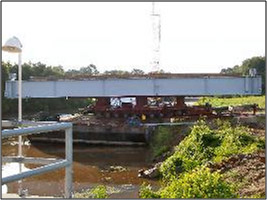
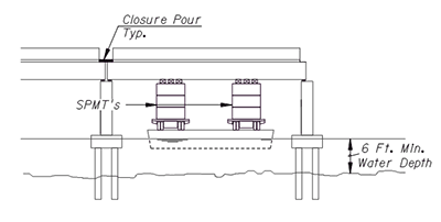
Exhibit C shows a water application where whole spans can be floated into place. This type of application has many benefits in that in addition to the speed of construction, the contractor's labor and insurance rates can be greatly reduced due to the reduced time on the water. Usually about a 6' water depth is necessary to allow barge access.
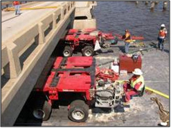
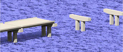
Using SPMT's to replace whole spans on the water may be an effective hurricane response strategy for many Gulf states because of its speed and cost benefits.
This application may be suitable for shored construction techniques to increase design efficiencies (20-30%). For de-icing states, where decks may need to be replaced in the future this may not be an option.
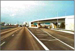
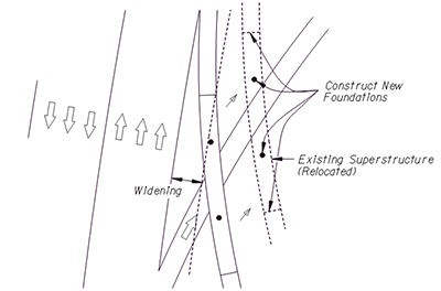
Exhibit G: SPMT's can be used to relocate existing bridges that would otherwise be demolished. Here is a case where an existing braided ramp superstructure is relocated onto new foundations to facilitate widening of the mainline highway.
There may be various ways to use SPMT technology to reuse existing structures within an interchange. The Owner needs to ask whether the new interchange can be reconfigured to make use of these existing bridge units? Can the adjacent interchange be reconfigured to utilize these spans? Also the existing bridge may be used as temporary bridges during bridge construction.

This video shows the construction sequence. First, the substructure and ramp approaches are constructed at their new location. Then the existing three-span unit is moved-in using SPMT's using a short closure to allow time to construct new bridge approach slabs and expansion joints and end bents.
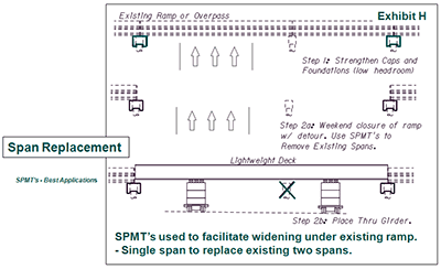
Exhibit H shows a special case where SPMT's can be used to retrofit an existing ramp or overpass to facilitate widening of the facility below. The concept involves replacing two spans of an existing overpass with a single span and eliminating the existing center pier. Strengthening of the existing piers to remain is likely due to increased loads of the longer span. A combination of shored construction, high strength materials, and lightweight concrete may be necessary to provide the structure depth requirements of the new longer span. A through girder configuration may also be necessary.
First, strengthen of existing caps and foundations "to remain" using low headroom equipment while overpass or ramp is still in service. Concurrently, construct the new span at an off-site / near site location. Second, close ramp or overpass traffic, remove and replace spans using SPMT's. Open ramp or overpass to traffic and remove existing pier and widening roadway or bridge underneath as required.
Whereas conventional construction would impact traffic for months SPMT's would reduce this impact to one weekend closure.
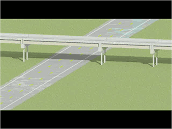
This video shows the construction sequence. First, the substructure and ramp approaches are constructed at their new location. Then the existing three-span unit is moved-in using SPMT's using a short closure to allow time to construct new bridge approach slabs and expansion joints and end bents.
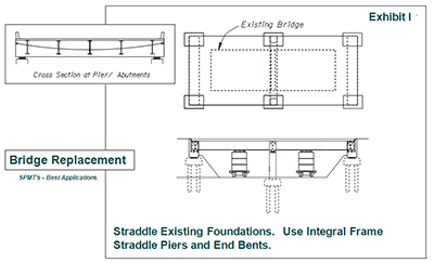
Exhibit I shows a straddle pier bridge replacement SPMT application where the foundations for the new longer bridge straddle the existing structure. This eliminates the need for phased construction.
First, construct new foundations either side of existing pier and end bents. Prefabricate new superstructure/ substructure integral pier/ end bent cap at an off site/ near site location. Next, remove the existing spans using SPMT's. Demolish the existing end bents and pier and move-in new superstructure/ substructure spans using SPMT's.
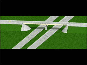
This video shows the construction sequence. First, the substructure and ramp approaches are constructed at their new location. Then the existing three-span unit is moved-in using SPMT's using a short closure to allow time to construct new bridge approach slabs and expansion joints and end bents.
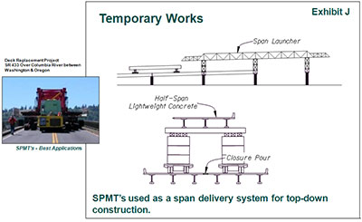
Exhibit J shows a special application where the SPMT serves as a span delivery system to an overhead span launcher for constructing a long viaduct. The unique flexibility of SPMT wheel configurations to better distribute the load of the half span (in this example) onto the existing structures may offer advantages over other more conventional delivery methods. This sort of top-down approach has applications on future managed lane projects where on long viaducts located in the median of existing interstates can greatly reduce construction impacts.
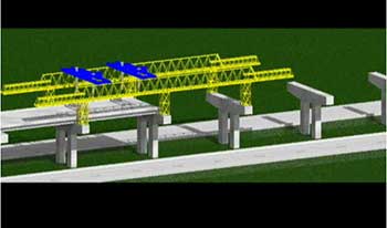
Construct precasting yard at one end of the viaduct. Construct pre-fabricated spans while constructing substructure elements of viaduct. Assemble span launcher and forward onto piers. Deliver prefabricated spans to span launcher using SPMT's. Place spans using span launcher. Forward span launcher, and repeat the process until viaduct is constructed. Note that the construction of the longitudinal closure pour is not on the critical path allowing for the construction of two spans a day or about one mile of viaduct a month.
Due to the number and uniformity of bridge elements, this sort of project is conducive to utilizing precast substructures.

