

| << Previous | Contents | Next >> |
Connection Details for PBES
Chapter 3 - Substructure Connections
This chapter is devoted to connections in substructure systems. The chapter has been broken out into typical substructure systems that are used on most bridges. These systems include piers, abutments, and walls. The connections between substructure elements that are directly connected to foundation elements (pile bents) will also be covered in this chapter.
3.1 Pier Elements
Prefabricated pier elements have been used by many state agencies. This is due to the difficulty of forming and pouring concrete high above the ground and the fact that substructures offer opportunities for repetition. There can also be significant savings by reducing construction time for substructure work over bodies of water or near hazards such as power lines.
3.1.1 Precast Concrete Cap Beam Connections
The most common prefabricated elements in substructures are pier cap beams. These elements are often the most difficult to construct using cast-in-place concrete, where shoring and forming can become significant.
Details presented in this manual were developed in states that are in low to moderate seismic zones. Many of the connections depicted cannot develop plastic hinges or do not include adequate confinement reinforcement. Several details developed by the Northeast States PCI Bridge Technical Committee may be appropriate for high seismic zones; however at this time research to verify their seismic performance has not been conducted and, therefore, they are still only recommended for moderate seismic zones.
There is research underway to investigate designs for prefabricated connections in high seismic zones. Users of this Manual should keep abreast of this research as it is completed. See Section 1.5 of this Manual for more information on this topic.
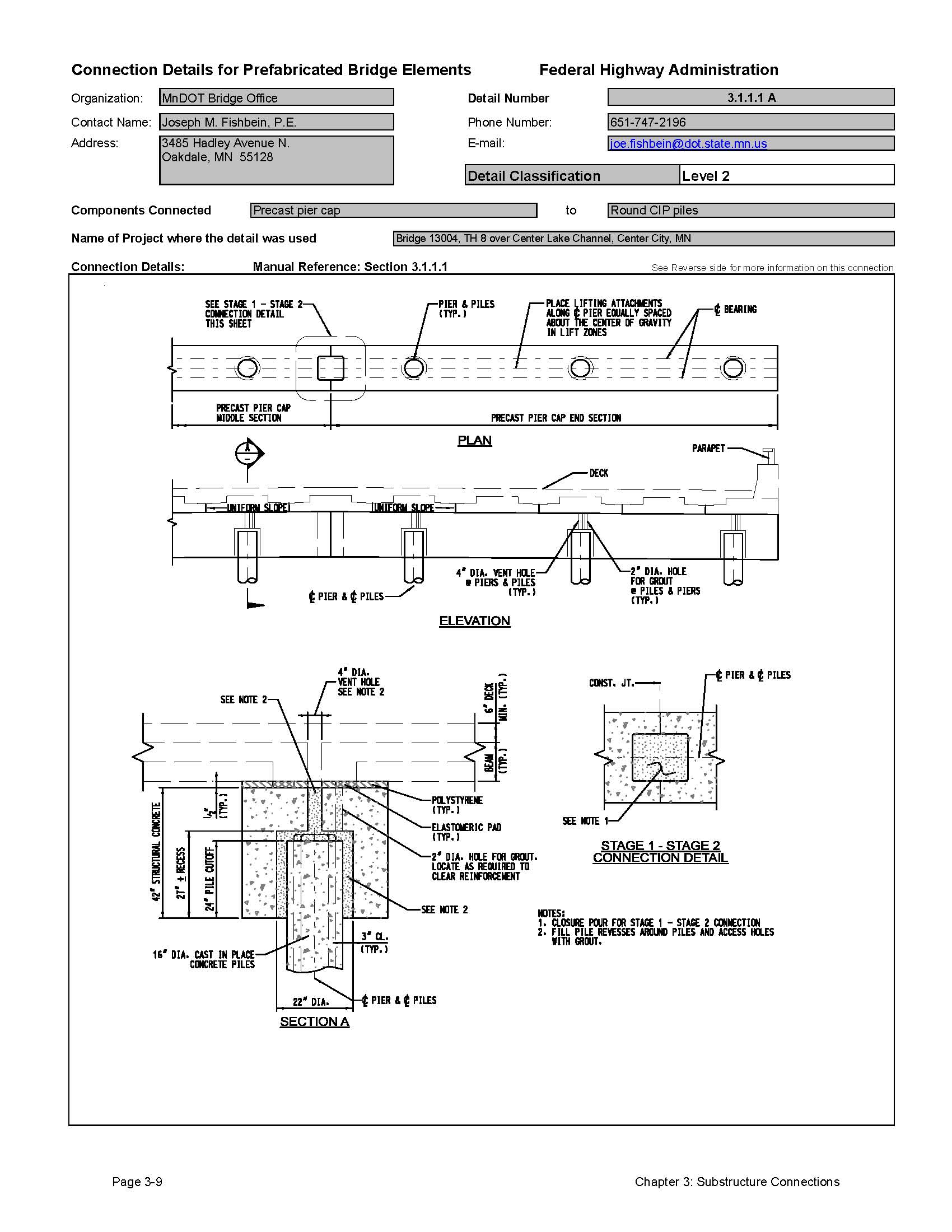
3.1.1.1 Connection to Cast-in-Place Concrete Columns and Piles
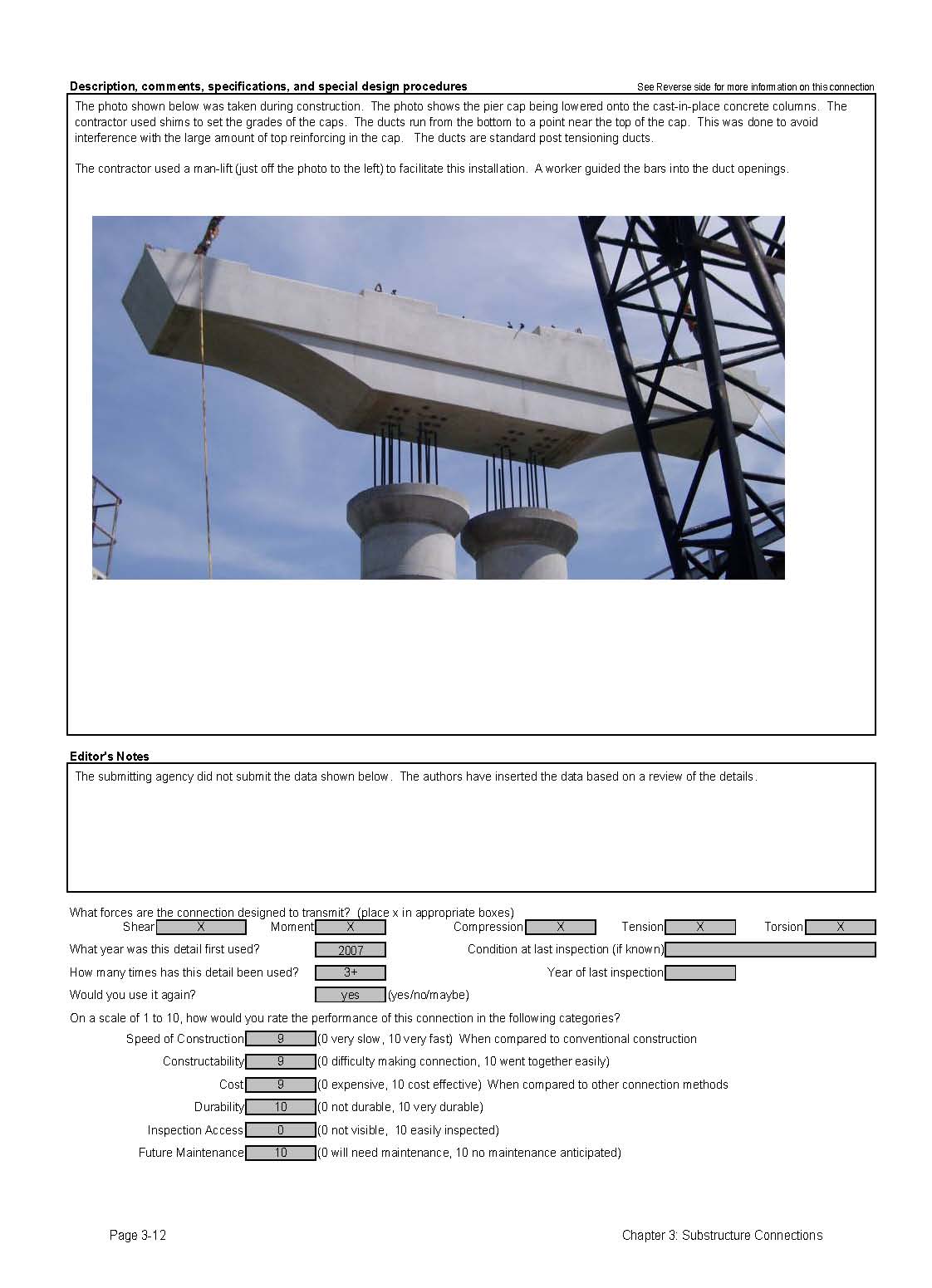
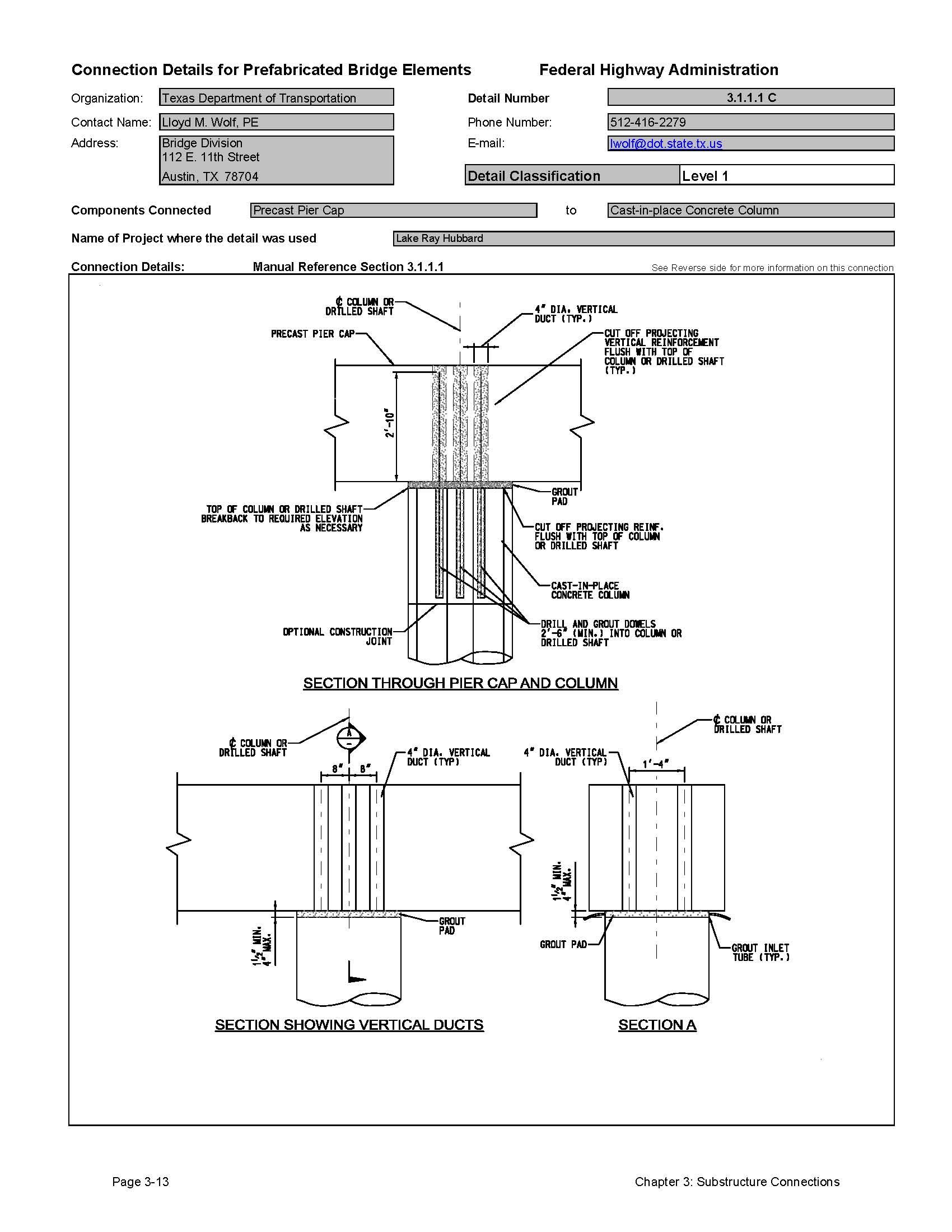
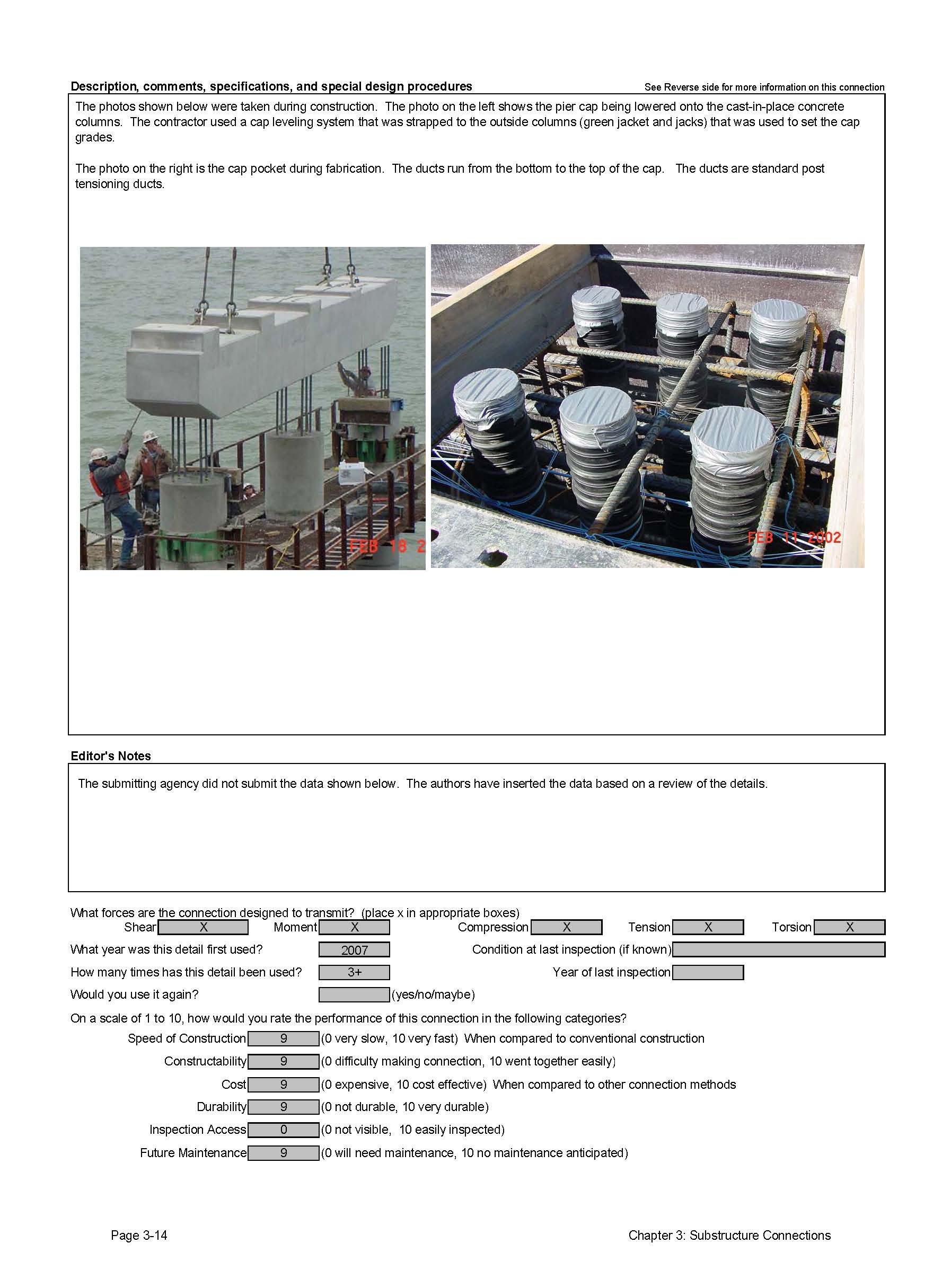
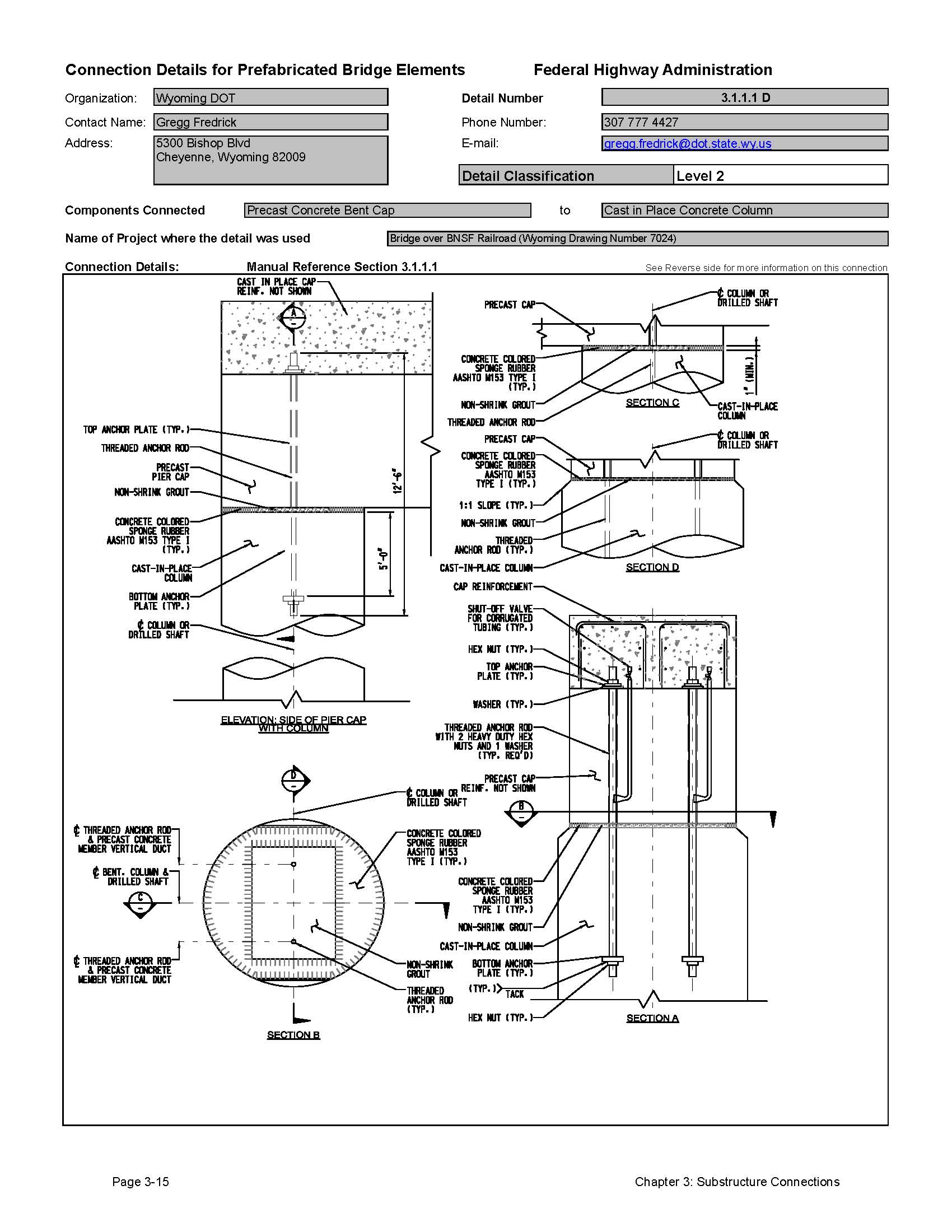
There have been several projects where precast concrete pier caps were connected to cast-in-place concrete columns and piles. The major issue with this approach is that the tolerance of the cast-inplace columns and piles needs to be addressed in the connection. Templates can be used to provide good fit-up in the field. Details using large blockouts in the pier cap element have been successfully built.
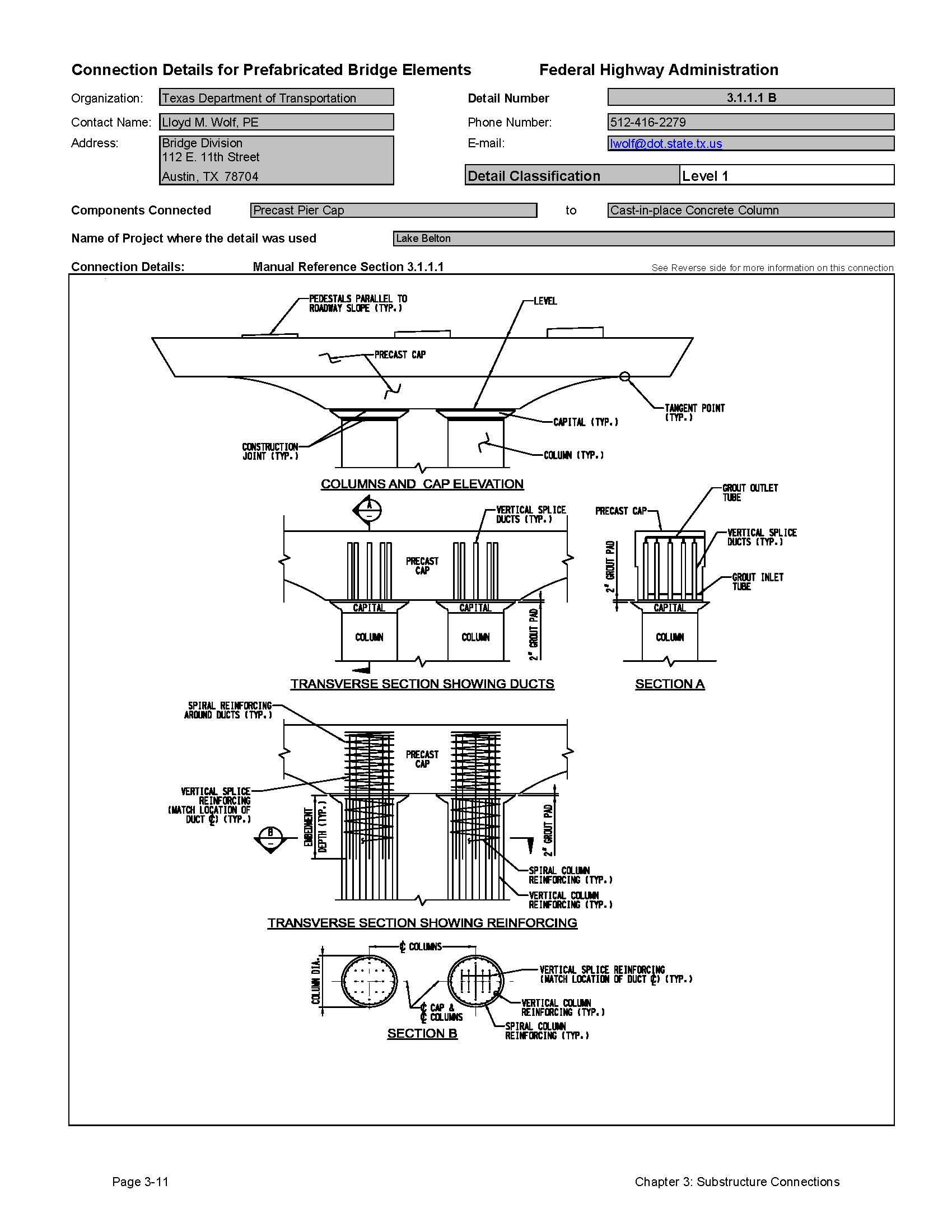
Texas DOT has built connections that employ standard posttensioning ducts to create voids for projecting reinforcing steel. These ducts, when combined with additional confinement reinforcing in the pier cap and grouted, can develop significant bending moment capacity; however research to verify their performance in moderateto- high seismic regions has not been completed [5]. More information on this connection can be found in the Texas DOT research report Number 1748-1 entitled "Development of a Precast Bent Cap System" [49]. Other states have used recessed grouted cap pockets to develop semi-moment connections, or simple bolted connections that would be considered a pinned connection.
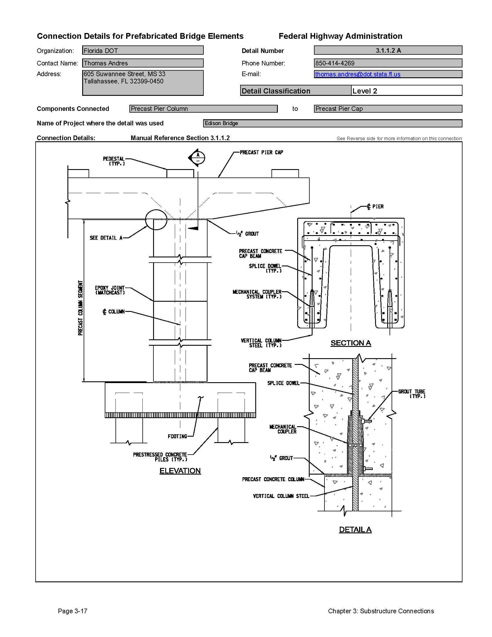
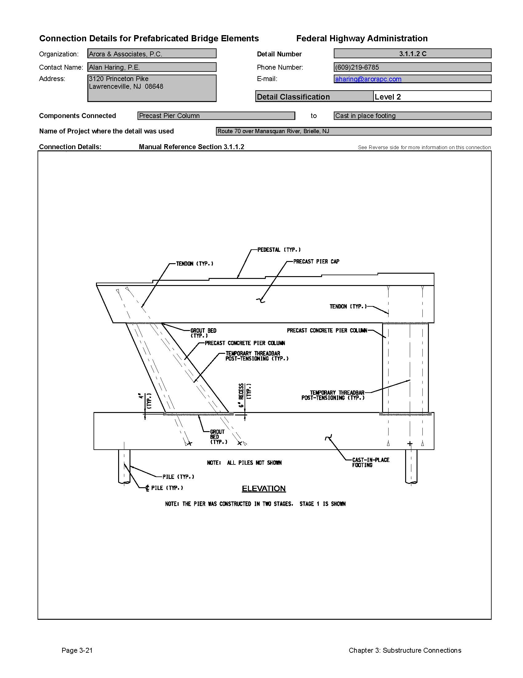
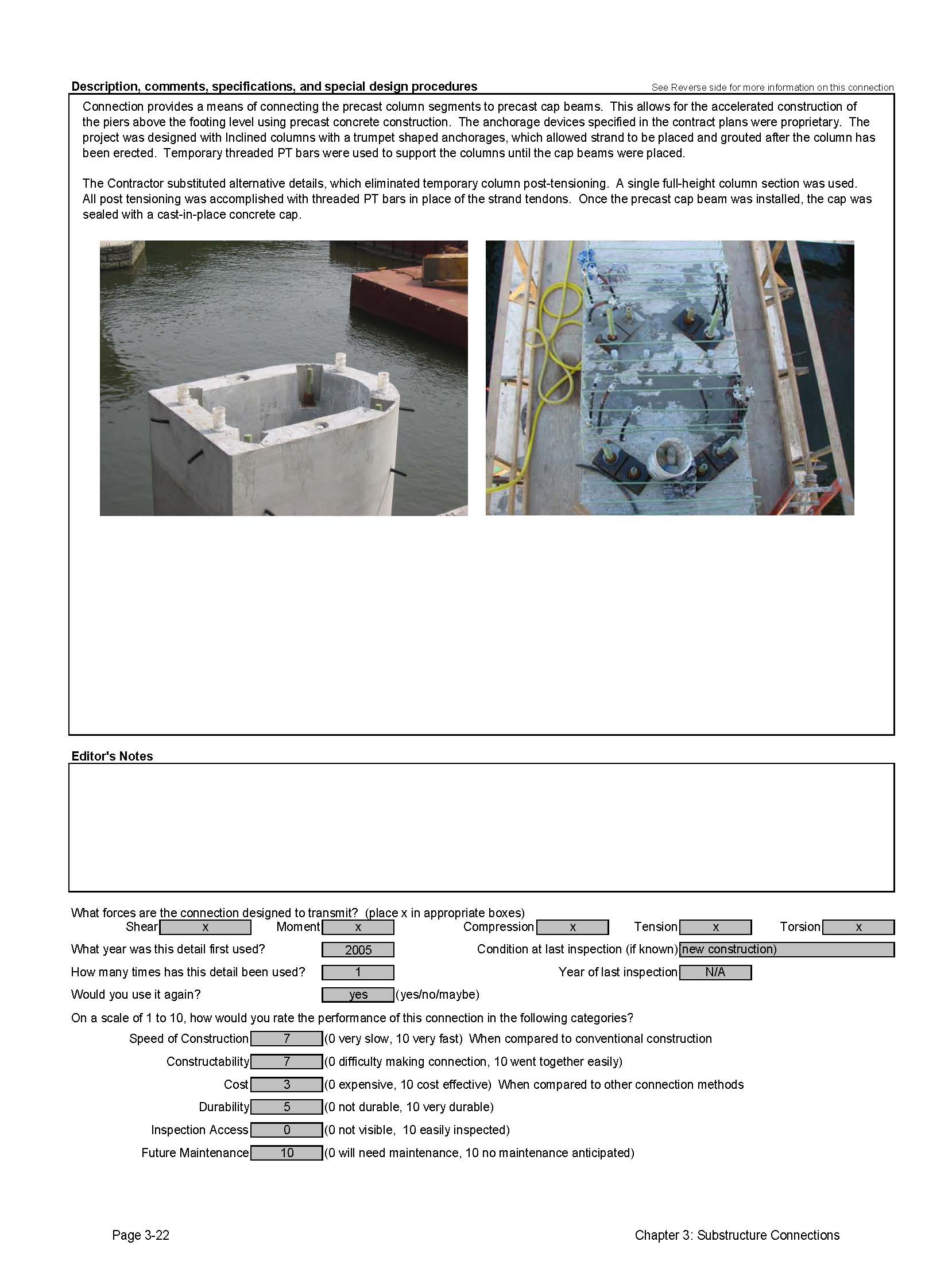
3.1.1.2 Connection to Precast Columns
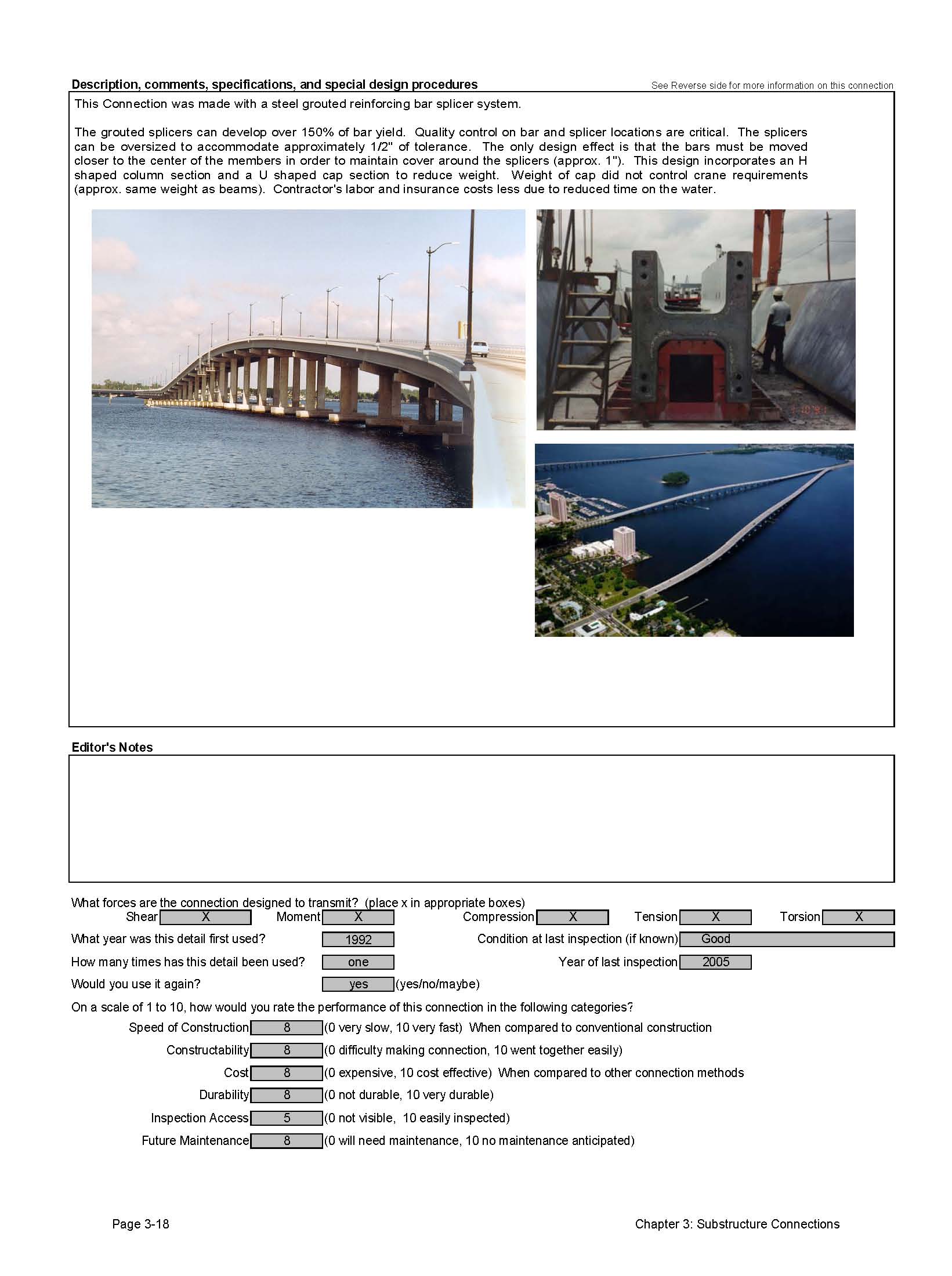
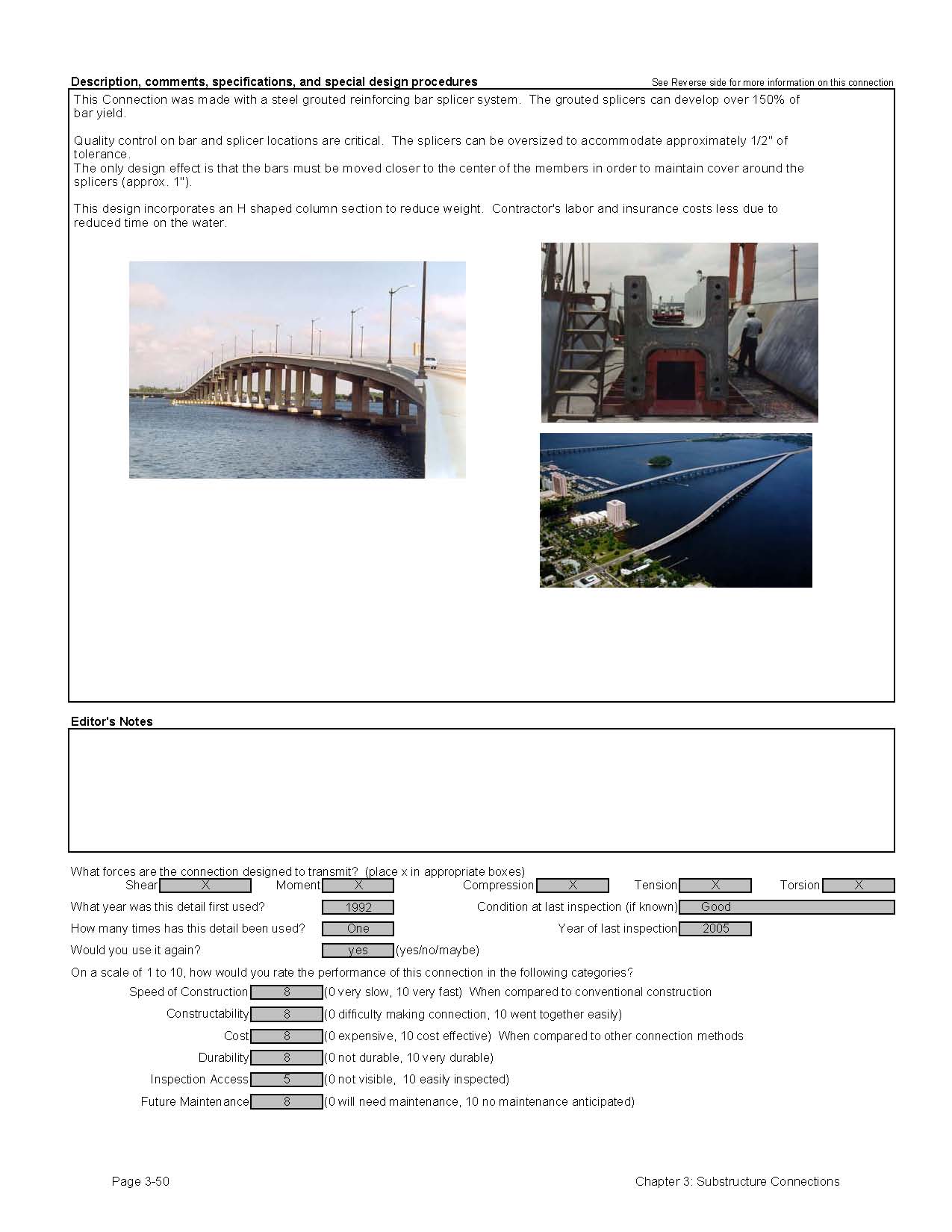
At least one state has constructed a pier bent using both precast concrete pier caps with precast concrete columns. Florida DOT built a large bridge called the Edison Bridge in Lee County. Figure 3.1.1.2- 1 shows the completed structure.
Figure 3.1.1.2-1 Edison Bridge
(Photo courtesy of Florida DOT)
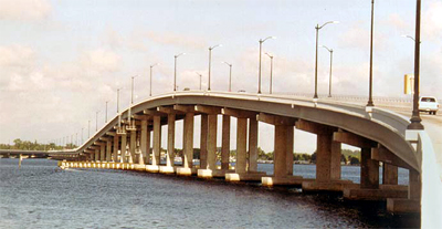
The Edison bridge pier connections used proprietary grouted splice couplers to create moment connections between the pieces. The couplers were embedded in the precast components and filled with grout after installation. The couplers used are proprietary; however there are multiple manufacturers of this type of coupler. This means that they can be used on federally funded projects. See section 1.4.2.1 for more information on these couplers.
Figure 3.1.1.2-2 Pier Column Section
(Photo courtesy of Florida DOT)
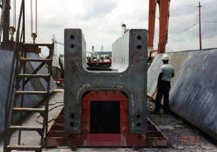
The columns and pier caps had unique shapes that were developed to reduce shipping and lifting weight of the elements. The columns were cast in an H shape, and the cap an inverted U shape. Figure 3.1.1.2-2 shows the column section during casting.
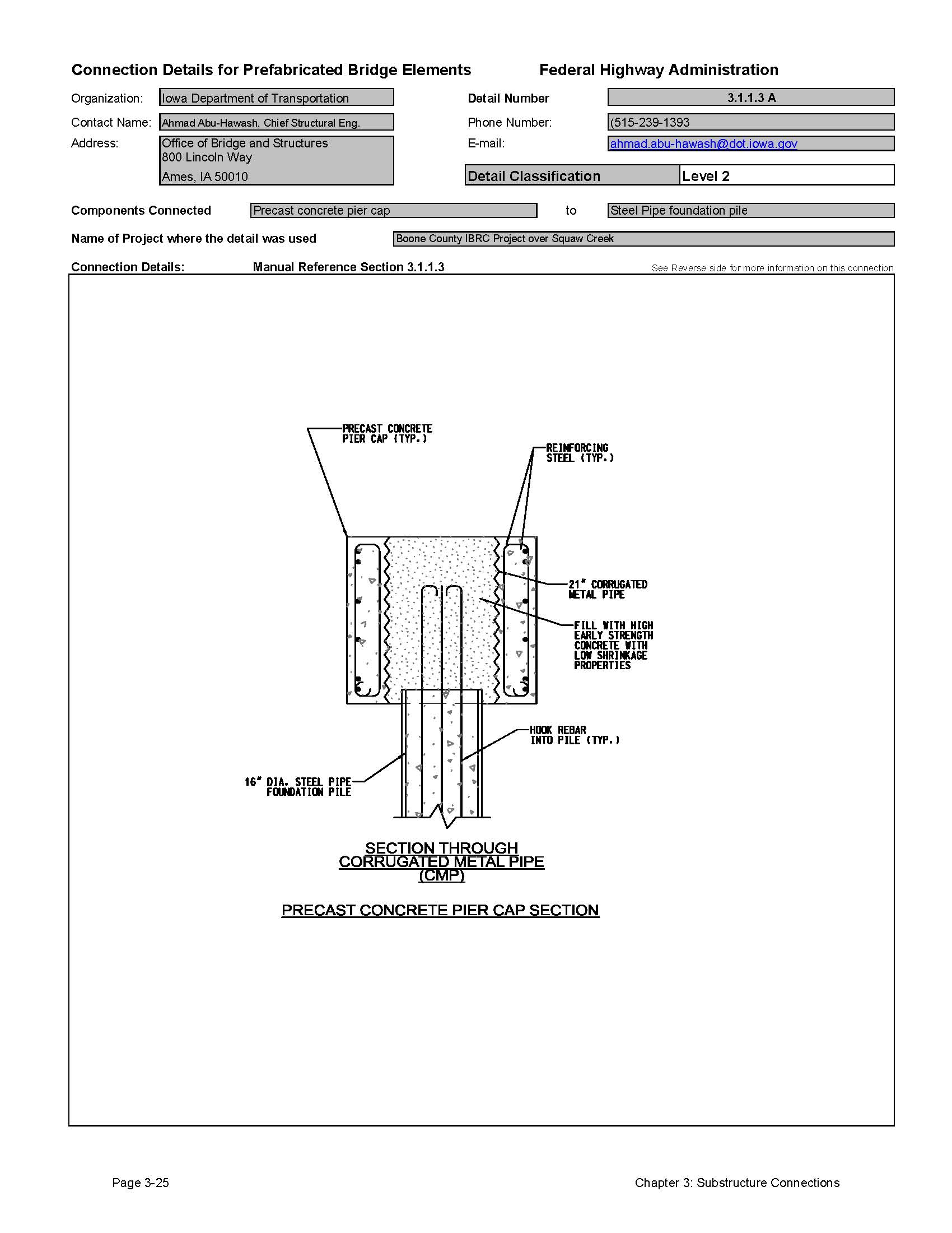
3.1.1.3 Connection to Steel Piles (pile bents)
Many states build simple pier structures that consist of driven steel piles supporting a reinforced concrete pile cap. These piers are referred to as pile bents.
Several states have developed details for prefabricated reinforced concrete bent caps. One option for the connection of the bent cap to the steel piles is a welded connection. The precast bent cap is built with embedded steel plates that are anchored in the precast bent with welded studs. After pile driving is complete, the steel piles are cut off to the proper elevation. The bent cap is placed over the piles and welded in place.
Some pile bents are constructed with hollow pipe piles. In this case, the connection of the pipe pile to the cap can be made by inserting reinforcing steel or an anchor rod into a void in the precast pile cap and the void in the pipe pile. A cast-in-place concrete closure pour in the pier cap void and the top of the hollow steel pile completes the connection.
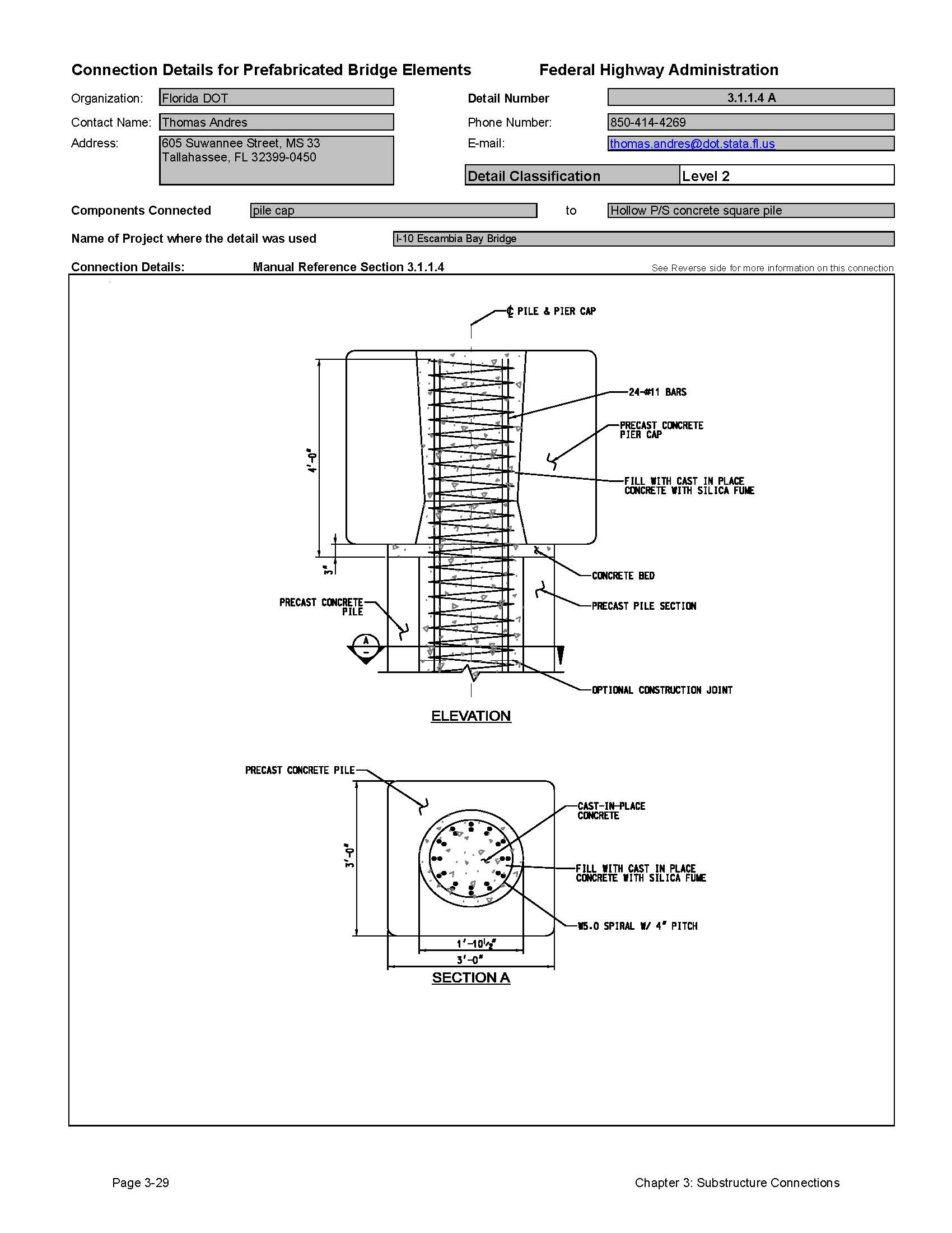
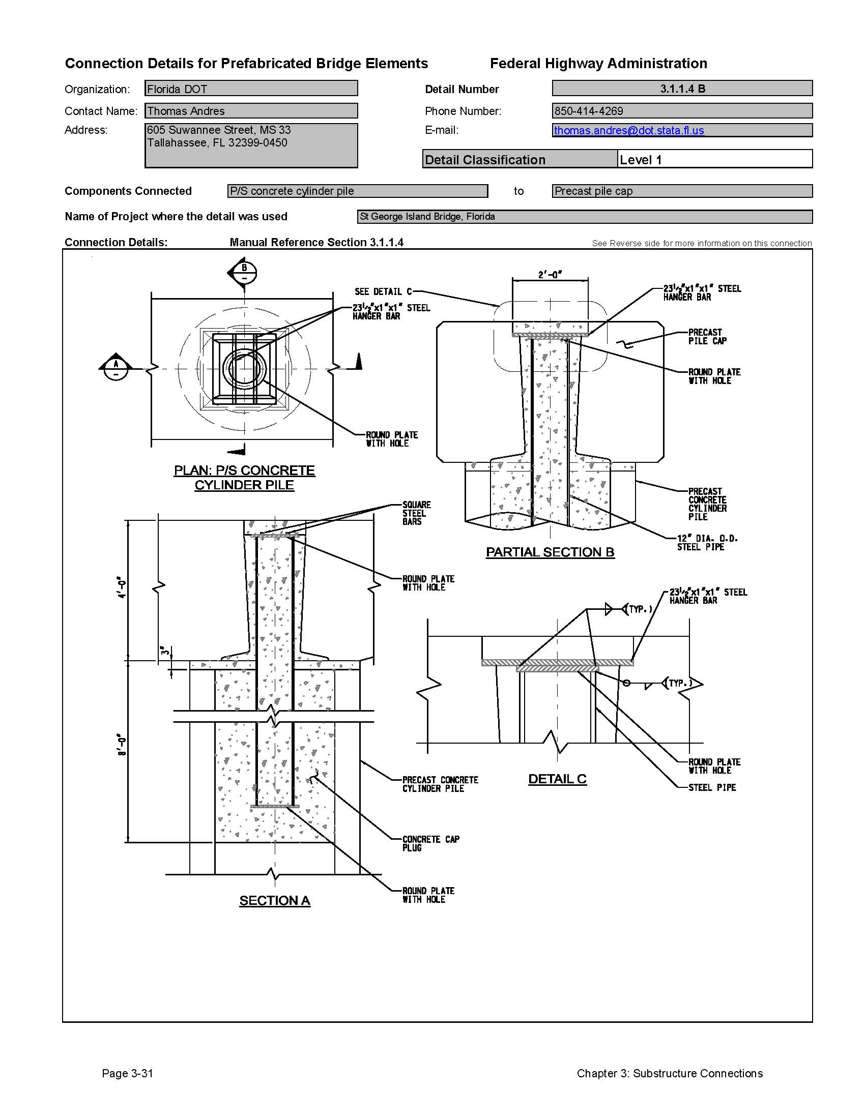
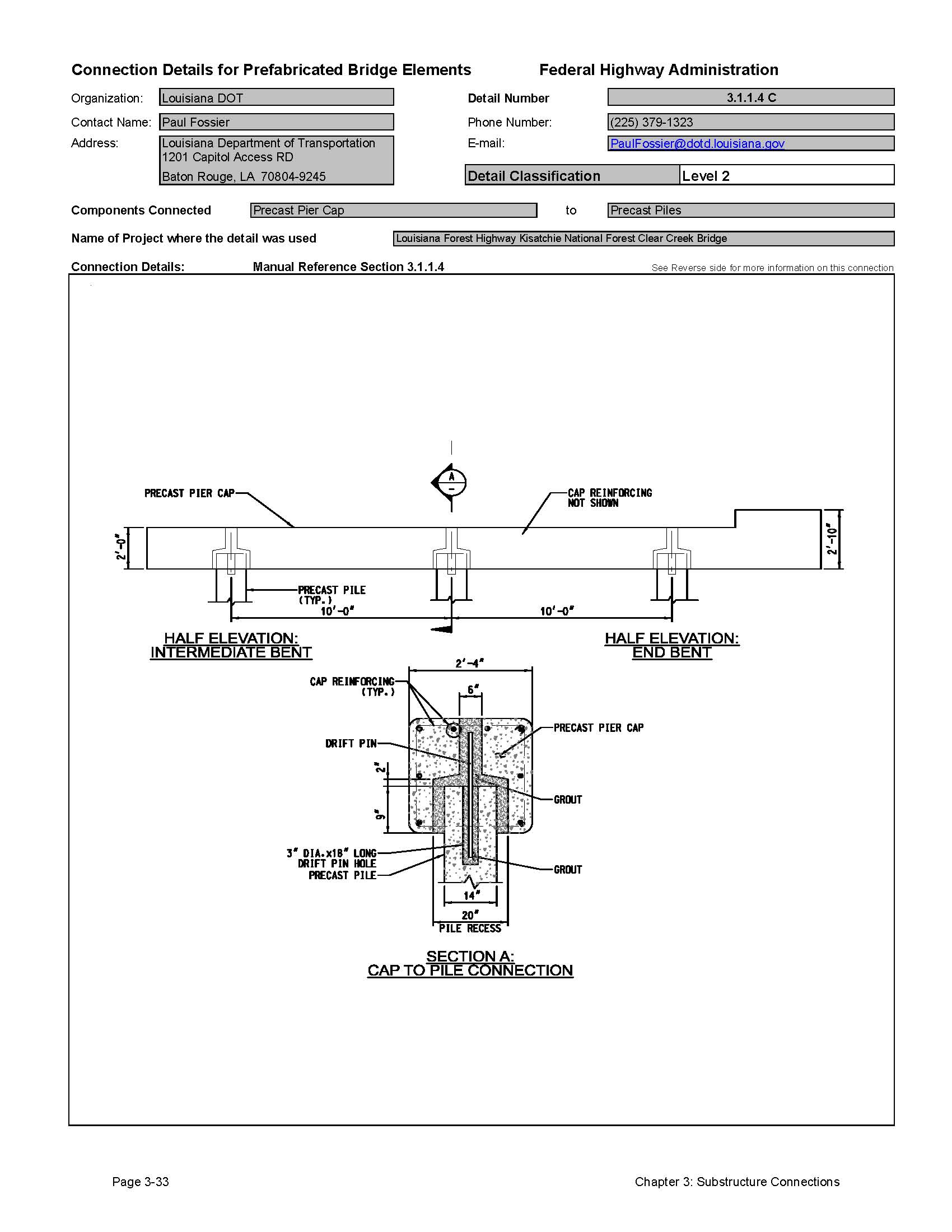
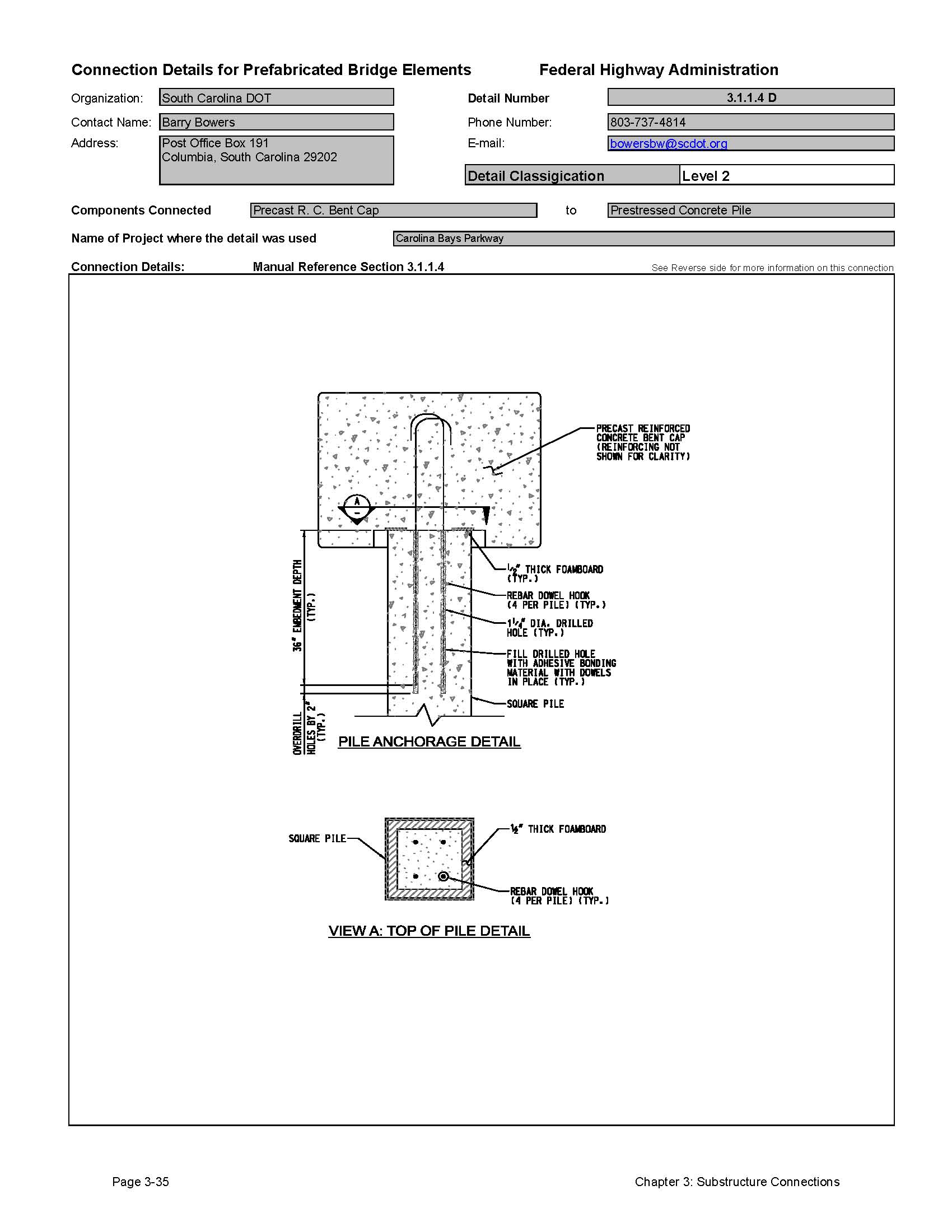
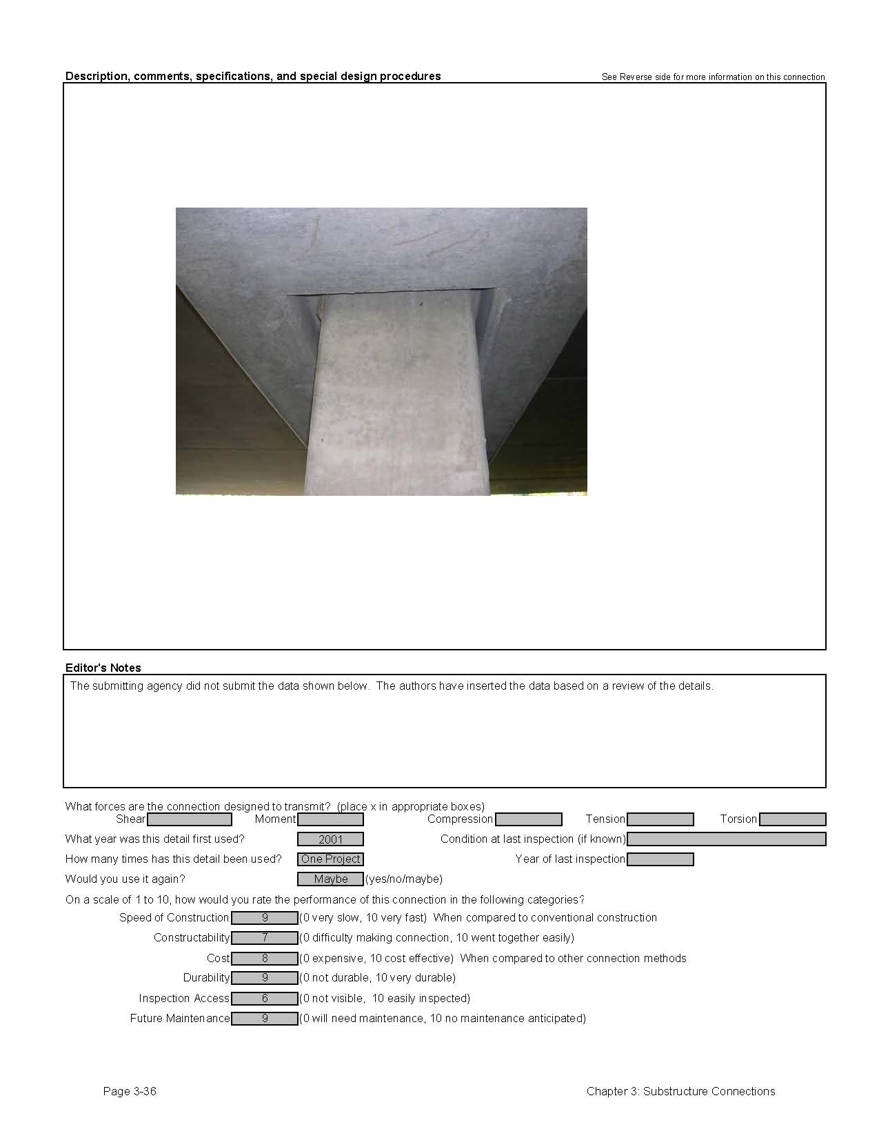
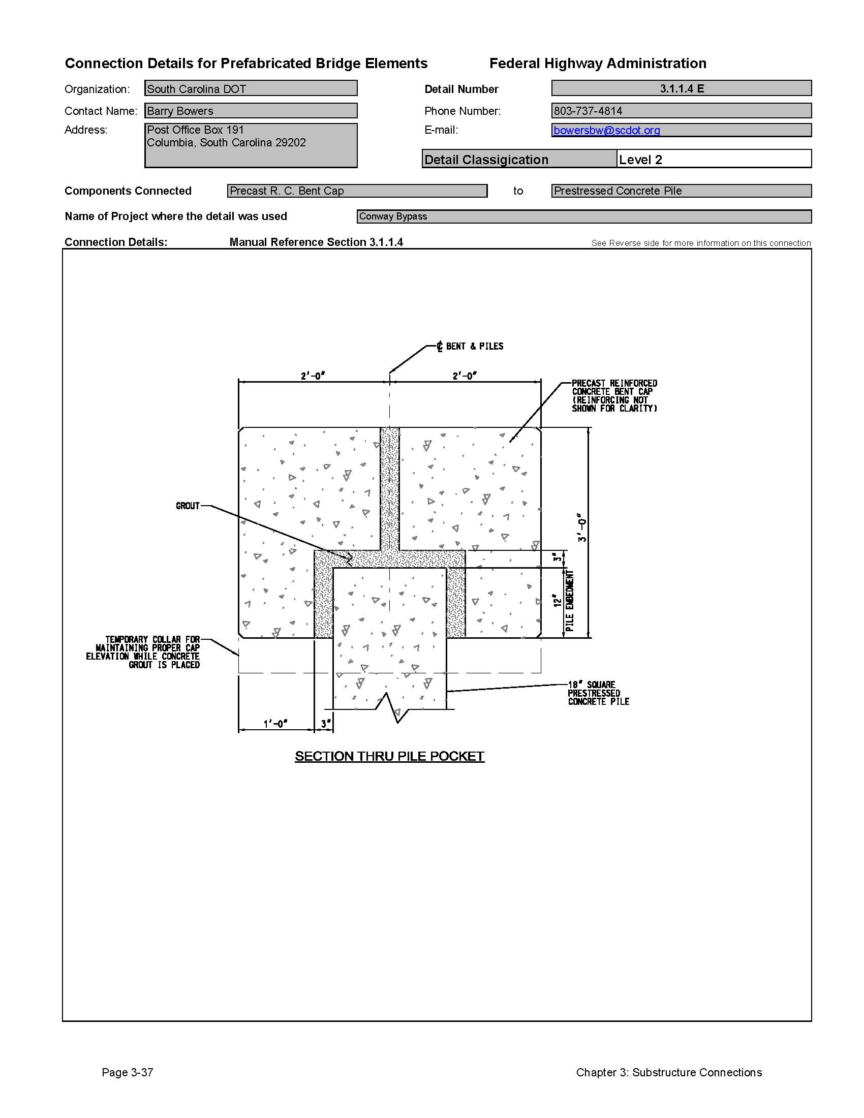
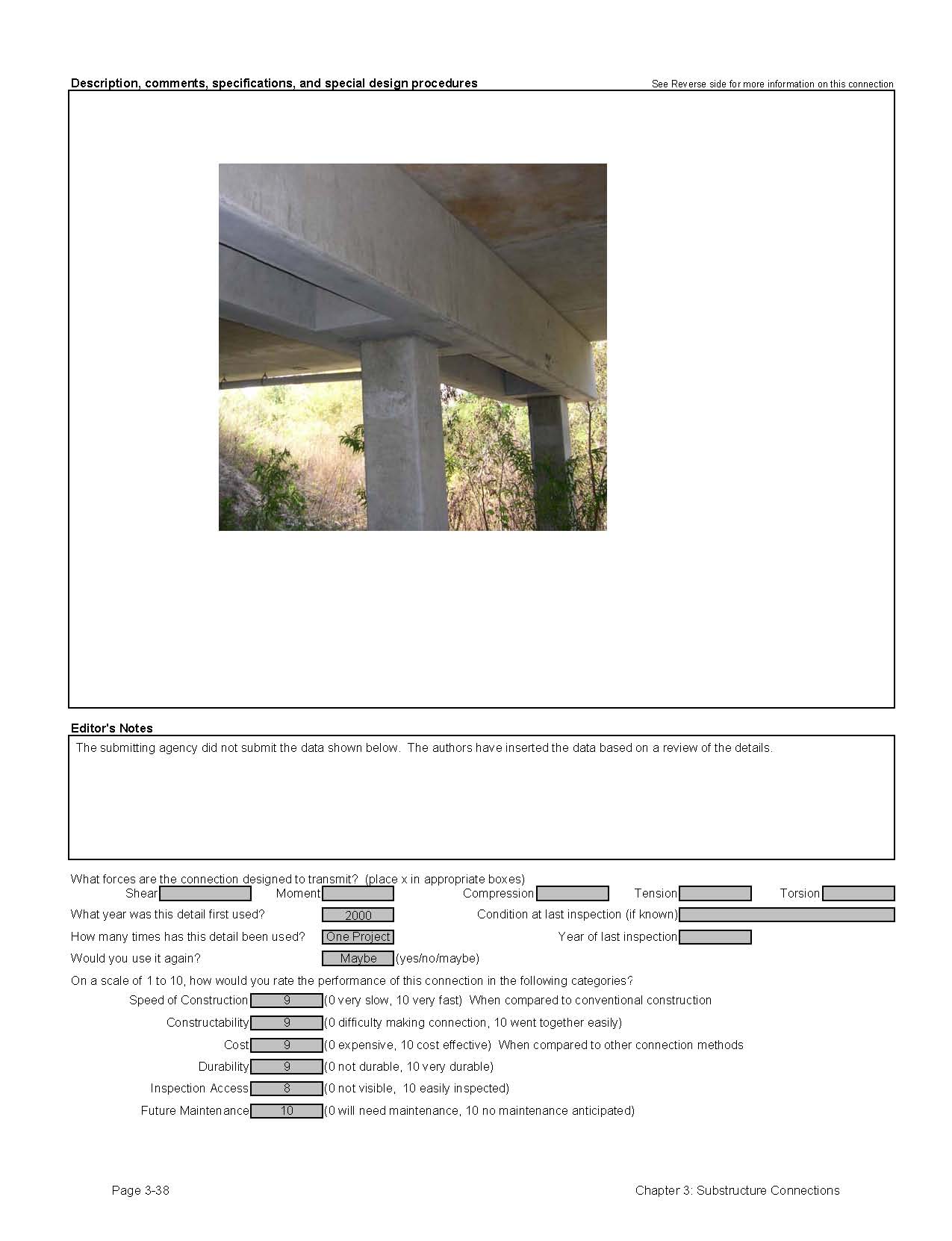
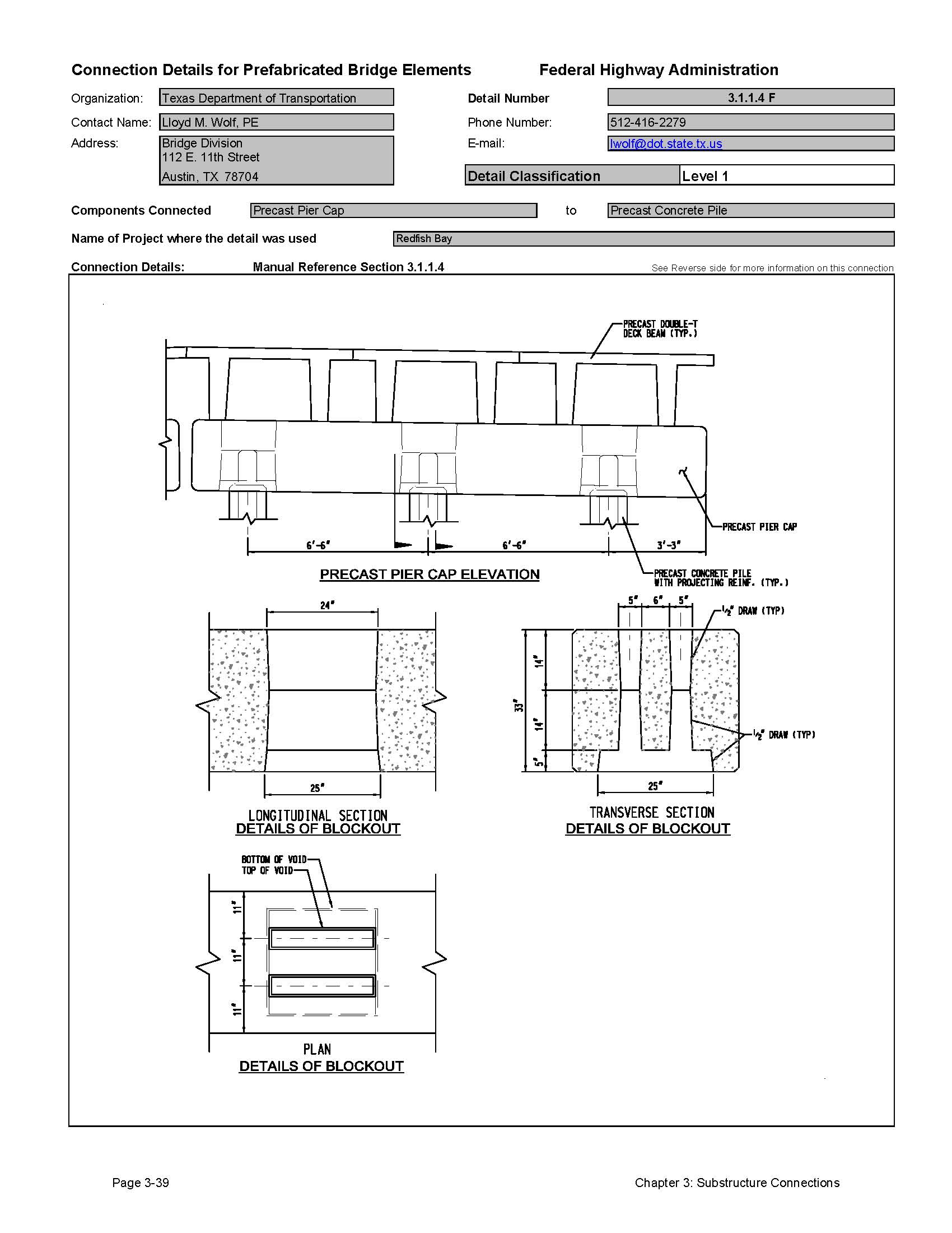
3.1.1.4 Connection to Precast Concrete Piles (pile bents)
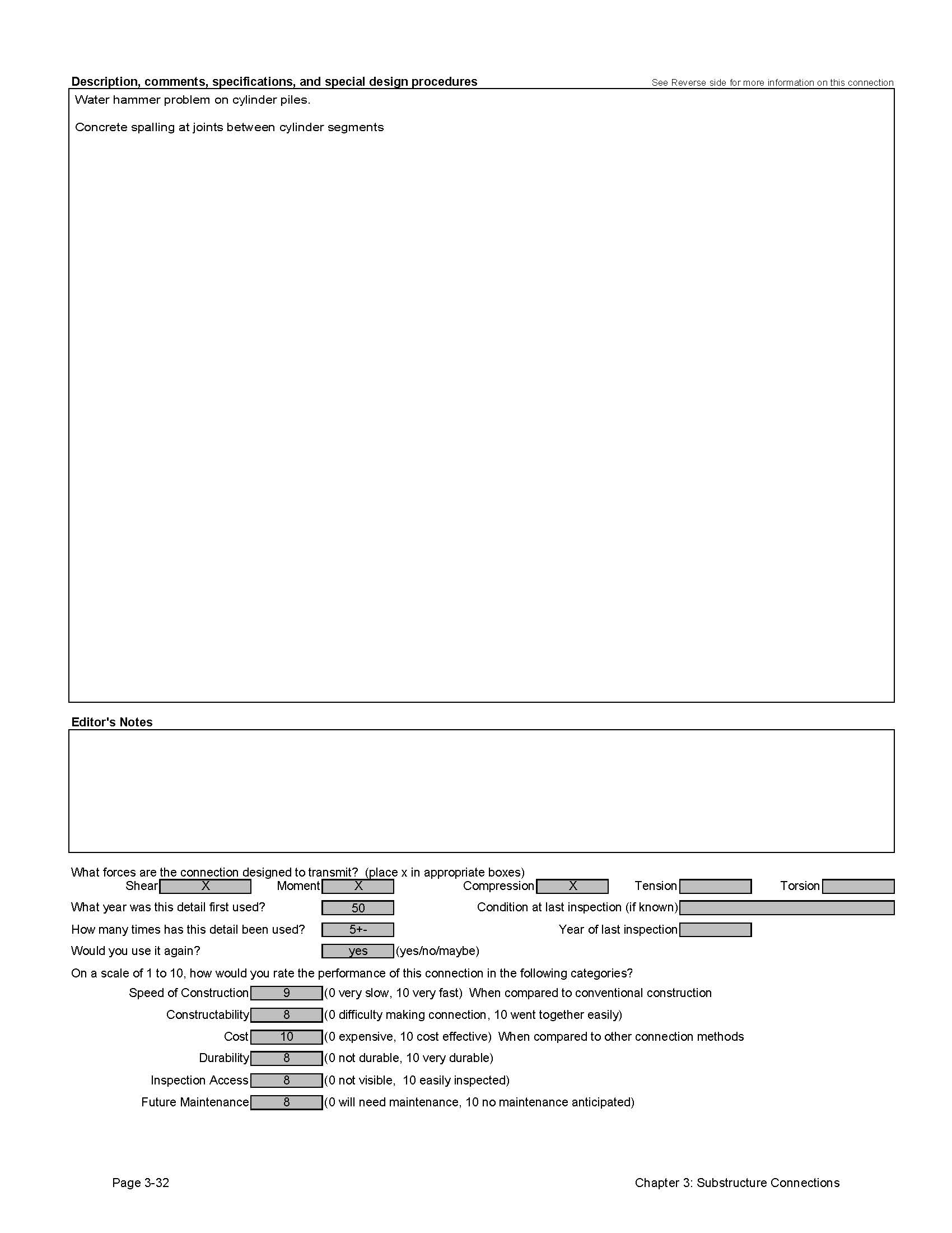
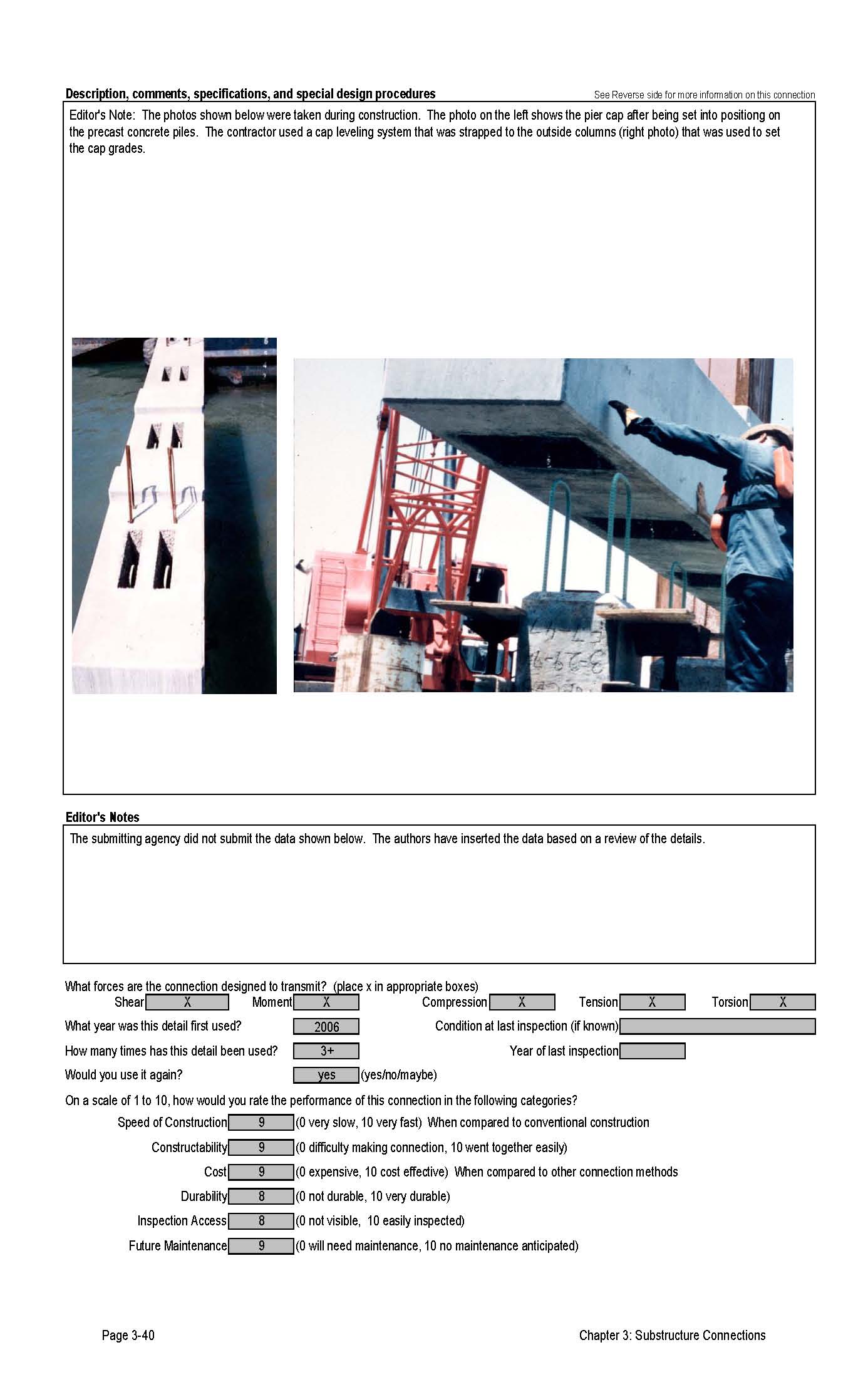
There are several details for connections of precast concrete pile caps to precast concrete piles. Most of these connections involve grouting the pile into a void in the pier cap. Some states use reinforcing in this connection.
Florida DOT uses large hollow precast piles for viaduct structures. The connection of these piles to the precast pier cap is similar to the connection of a precast pier cap to a hollow steel pile. A reinforced closure pour is used to connect the two elements.
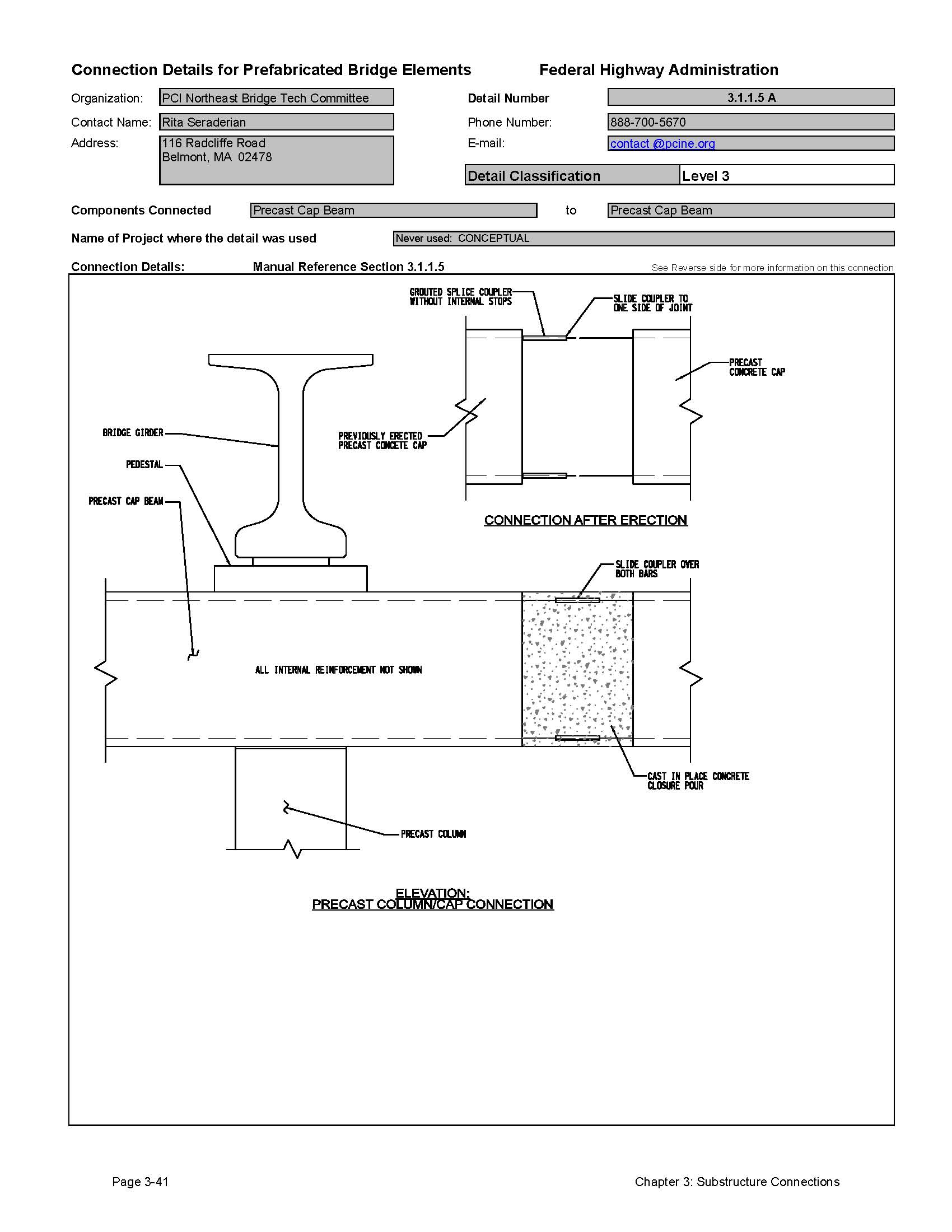
3.1.1.5 Connection of Precast Concrete Cap to Precast Concrete Cap
There are several reasons to construct precast pier caps in several pieces and connect them in the field. On wide bridges, it may be desirable to have a very wide pier cap. Shipping limitations (dimensions) may require that the cap be manufactured in multiple pieces. Also, if the cap pieces are very heavy, it may be desirable to build the cap in multiple pieces to limit the size of cranes on site. Another reason to use multiple cap pieces is to facilitate fit up in the field. Connecting a precast cap to three or more columns is not impossible, but it is easier to connect to two columns. Designers should consider incorporating open joints in pier cap designs. This will facilitate the erection of caps and reduce the thermal forces in the pier bents.
One of the details submitted by the Northeast PCI Bridge Technical Committee shows a cast-in-place closure pour. This is done because it is very difficult to erect two components with a horizontal connection using grouted reinforcing bar couplers. The time to cure a closure pour might seem to be a problem with accelerated construction methods; however if detailed properly, this connection can be designed to support only loads placed on the structure after erection of the beams. This means that the erection process can proceed while this connection is formed, poured and cured.
3.1.2 Precast Concrete Column Connections
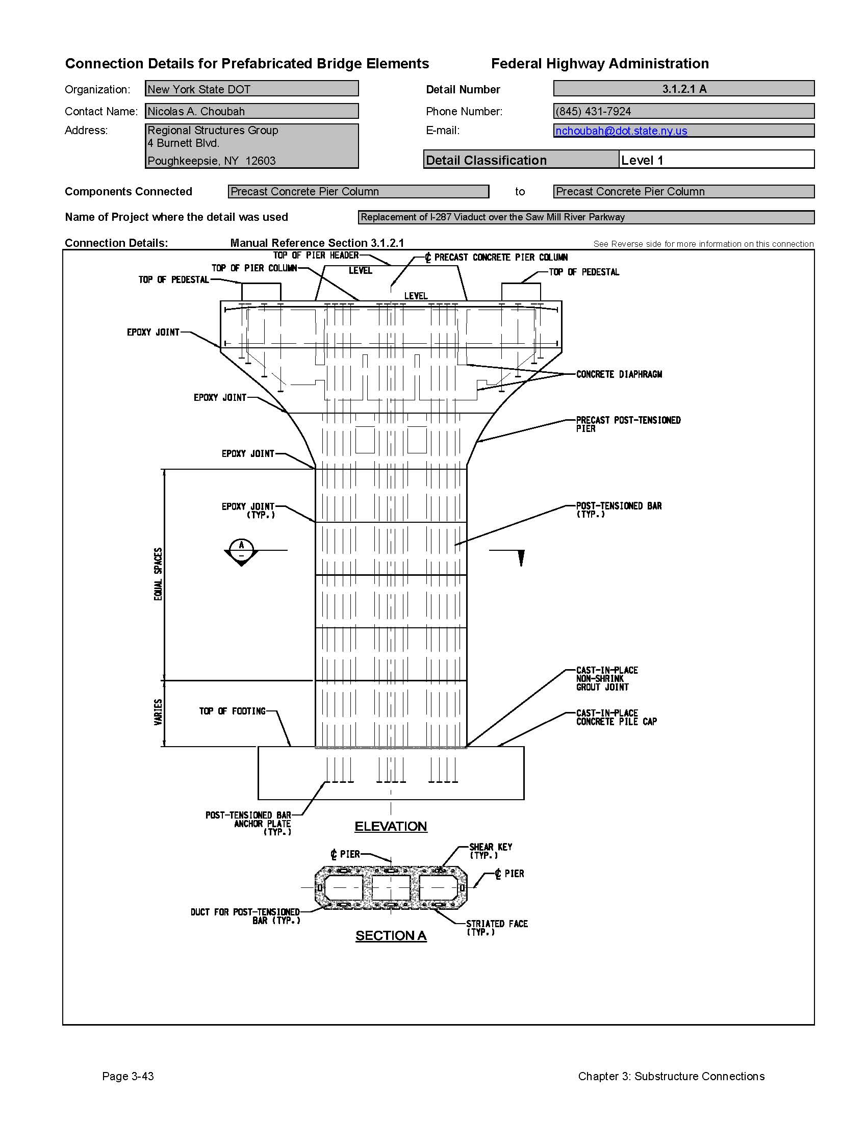
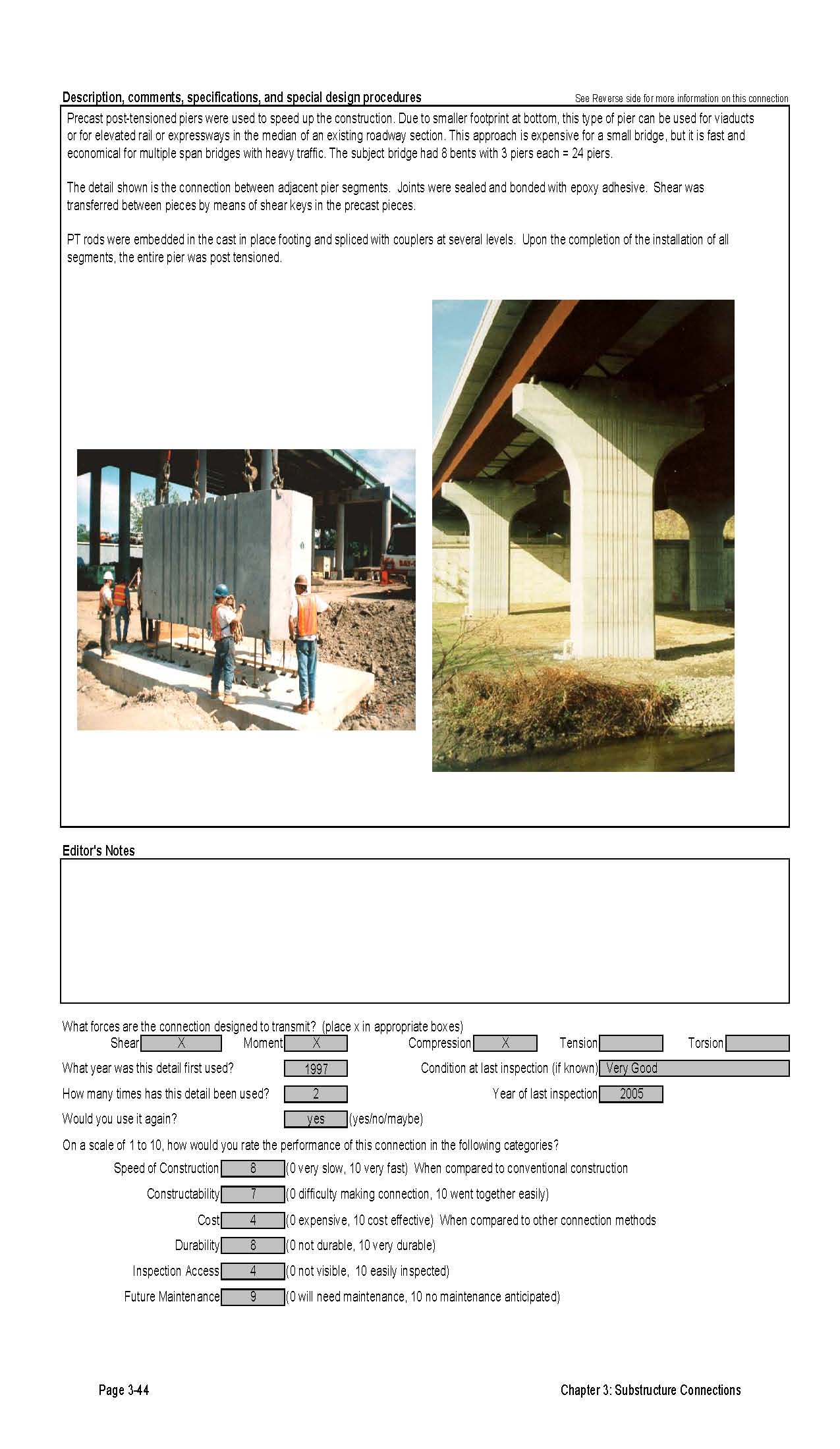
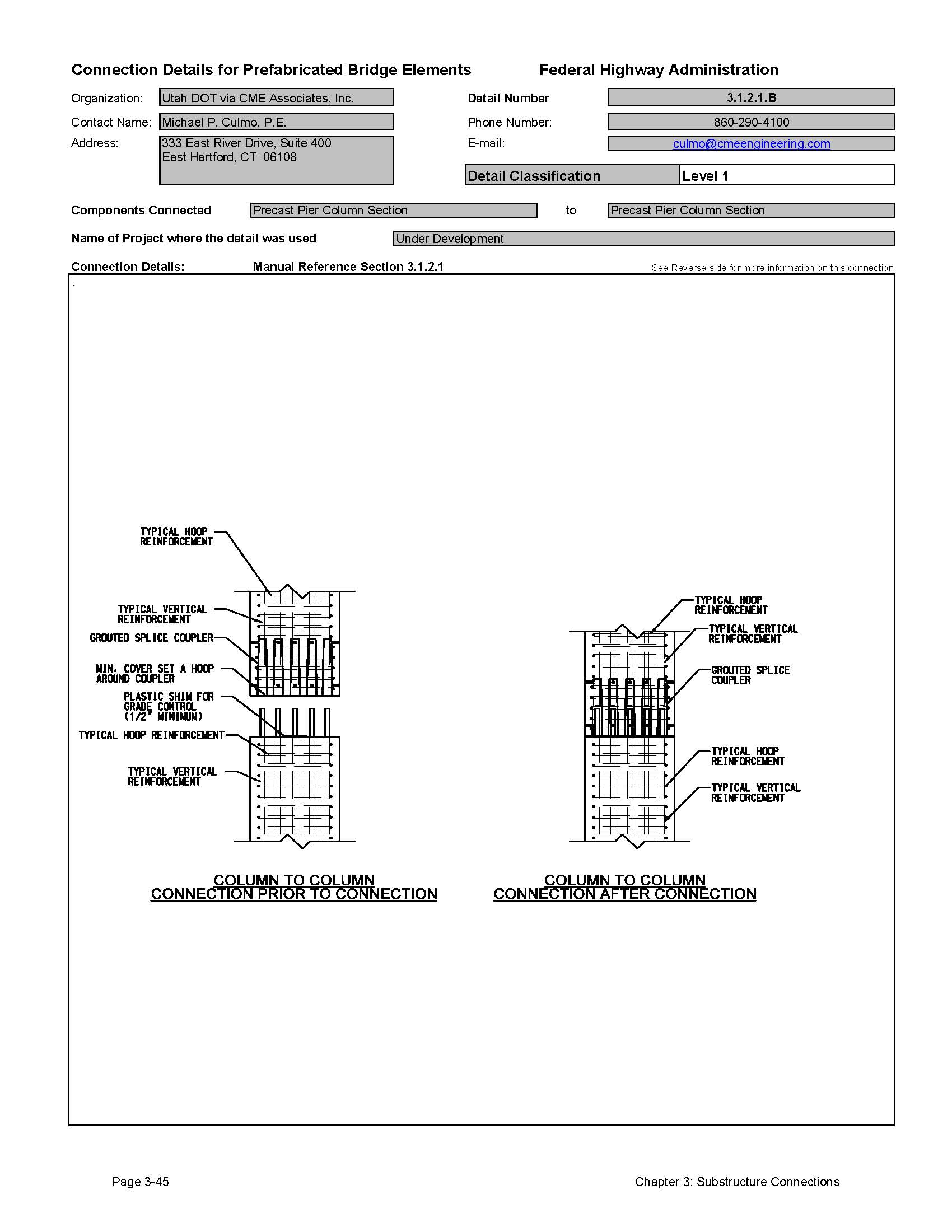
3.1.2.1 Connection of Column to Column
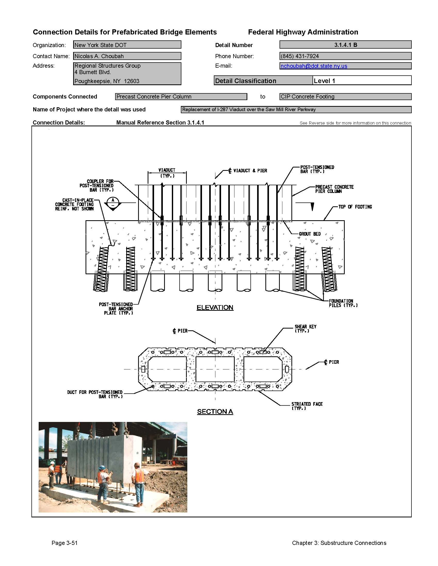
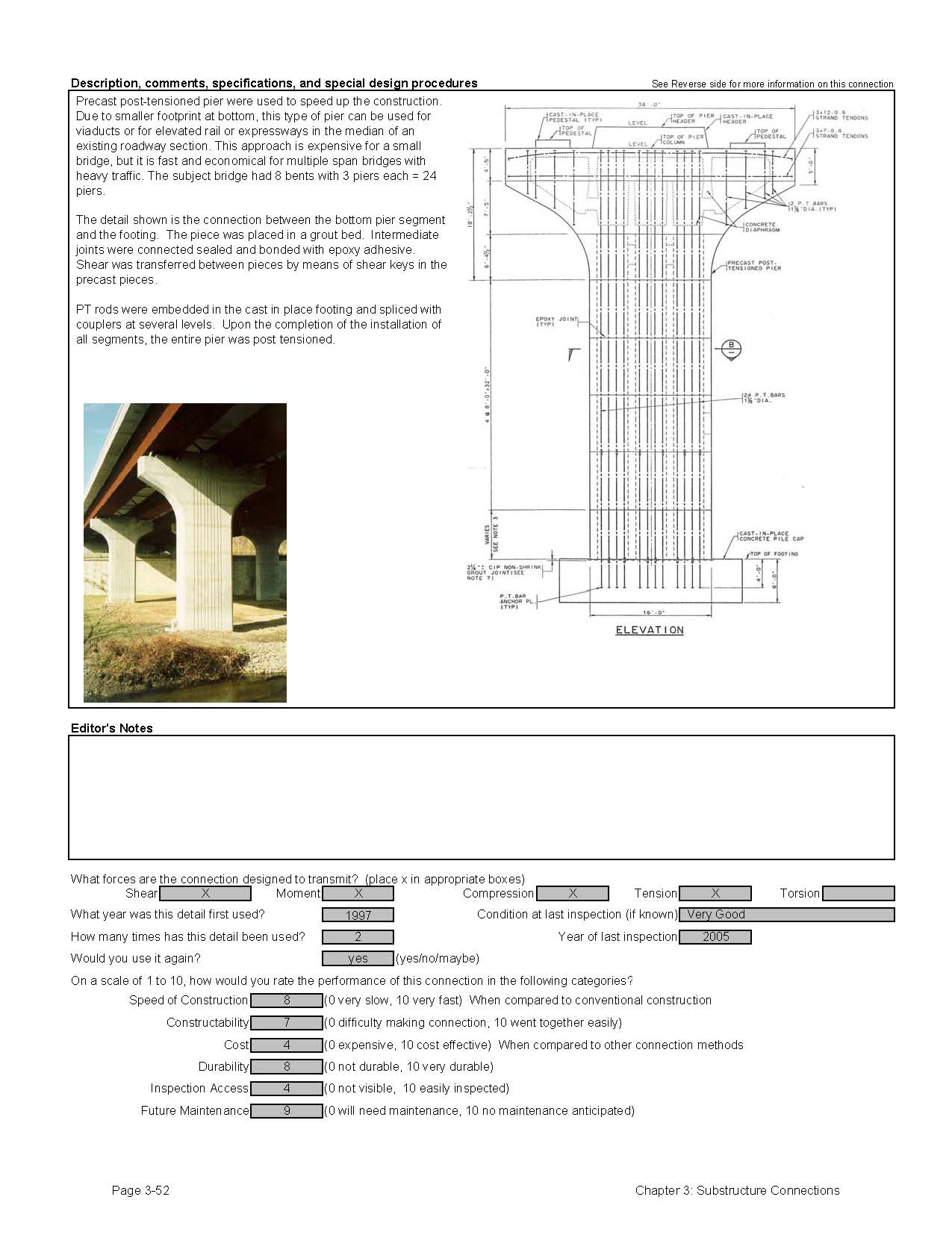
Few states have designed bridges with prefabricated pier column connections. The connections were made by using the match cast method of construction combined with post-tensioning. The joints are epoxy bonded together and the post-tensioning completes the joint.
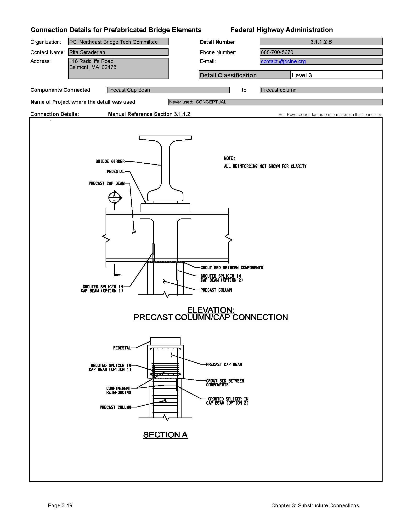
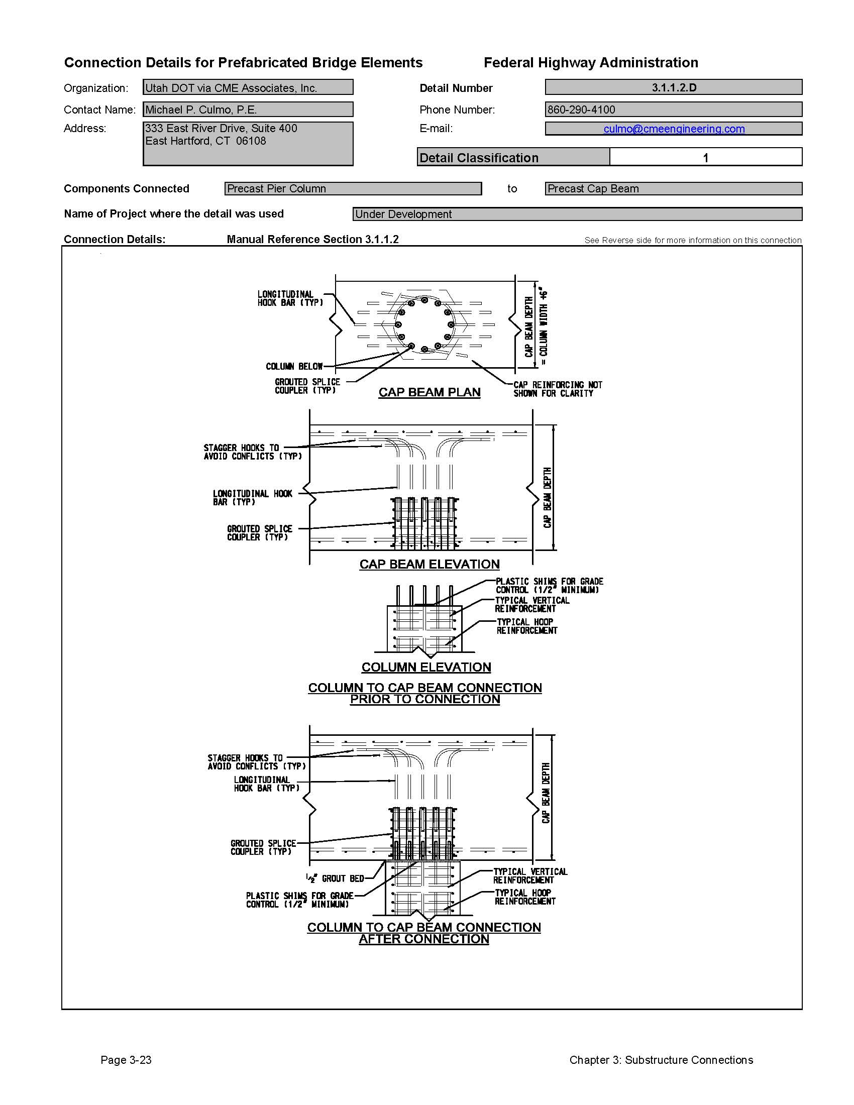
The details for column connections that are proposed by the Northeast States PCI Bridge Technical Committee could also be used for this connection. This type of connection uses grouted reinforcing splice couplers to connect the reinforcing from one element to the next. This type of connection has been used in stadium construction projects. See Section 3.1.1.2 for more information on this type of connection.
3.1.3 Wall Pier Connections
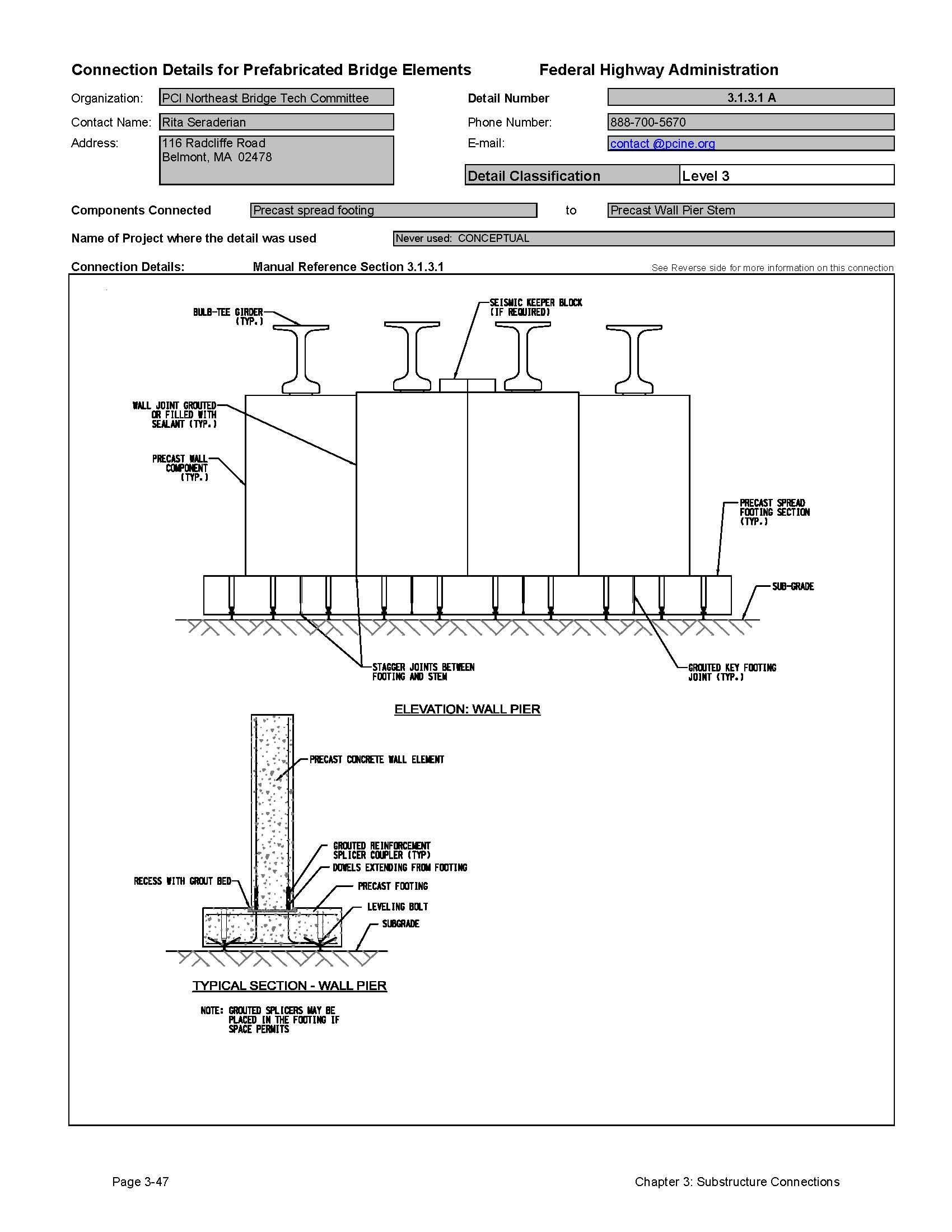
3.1.3.1 Connection of Precast Wall to Precast Footing
The Northeast States PCI Bridge Technical Committee has developed details for a precast concrete wall pier. While this type of structure has not been constructed yet, a precast cantilever wall abutment has been successfully built. The details are essentially the same except the structure does not support unbalanced soil loads. The pier elements can be connected using grouted shear keys or simply sealed to prevent moisture infiltration. See Section 3.2.1 for more information on these connections.
Other connections described in this section for precast pier columns can easily be applied to wall piers. For instance, a precast wall pier element can be connected to a cast-in-place concrete footing as described in Section 3.1.4.1 below.
3.1.4 Precast Concrete Column to Footing Connections
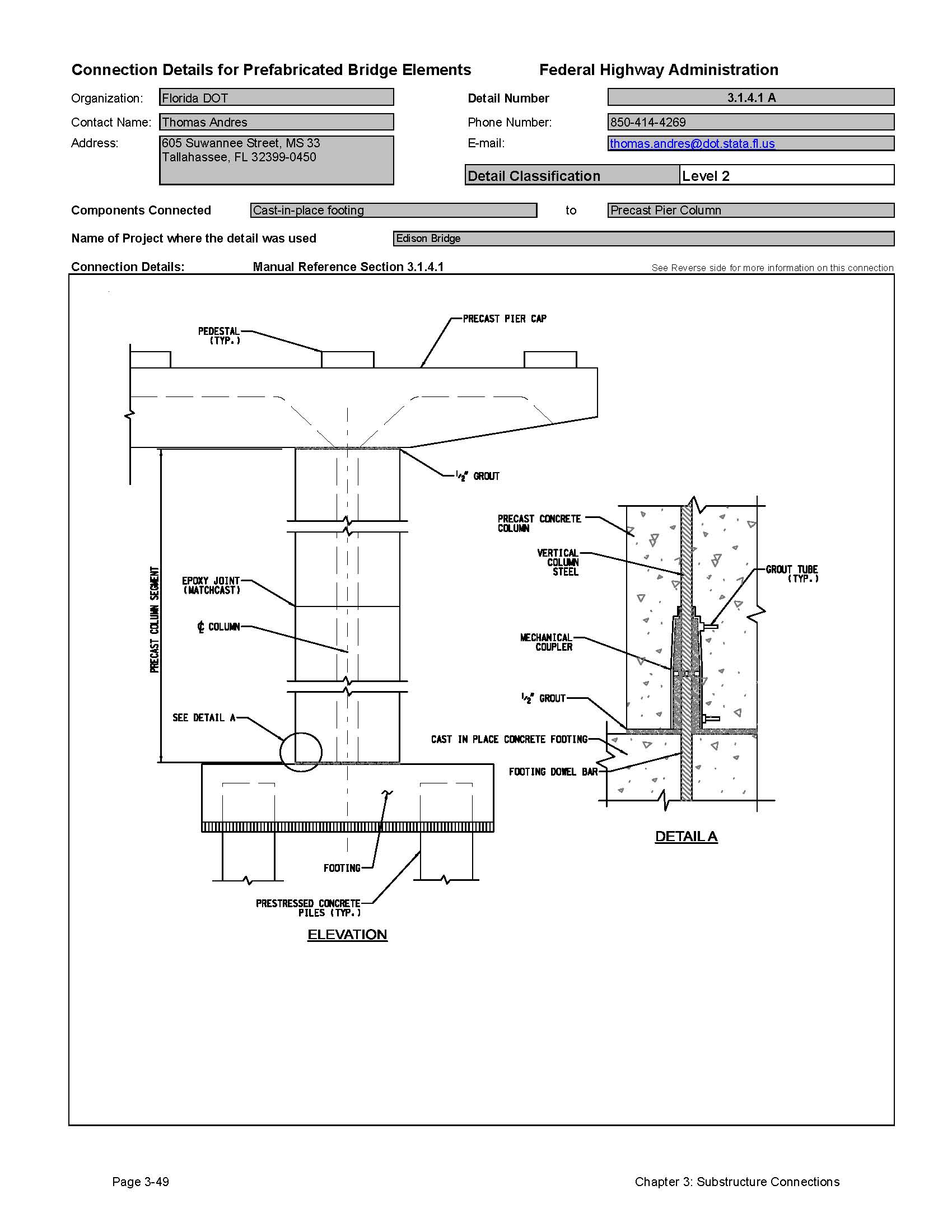
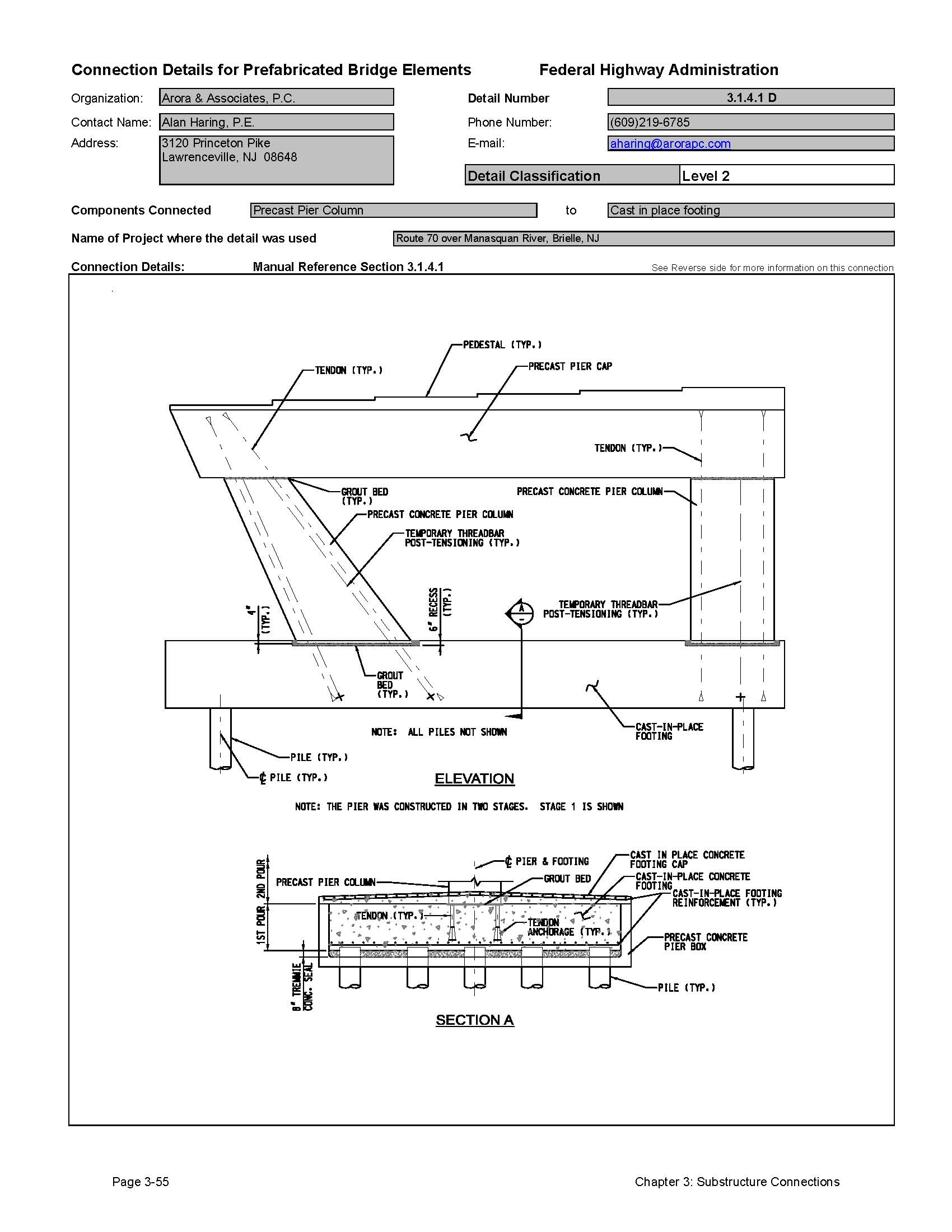
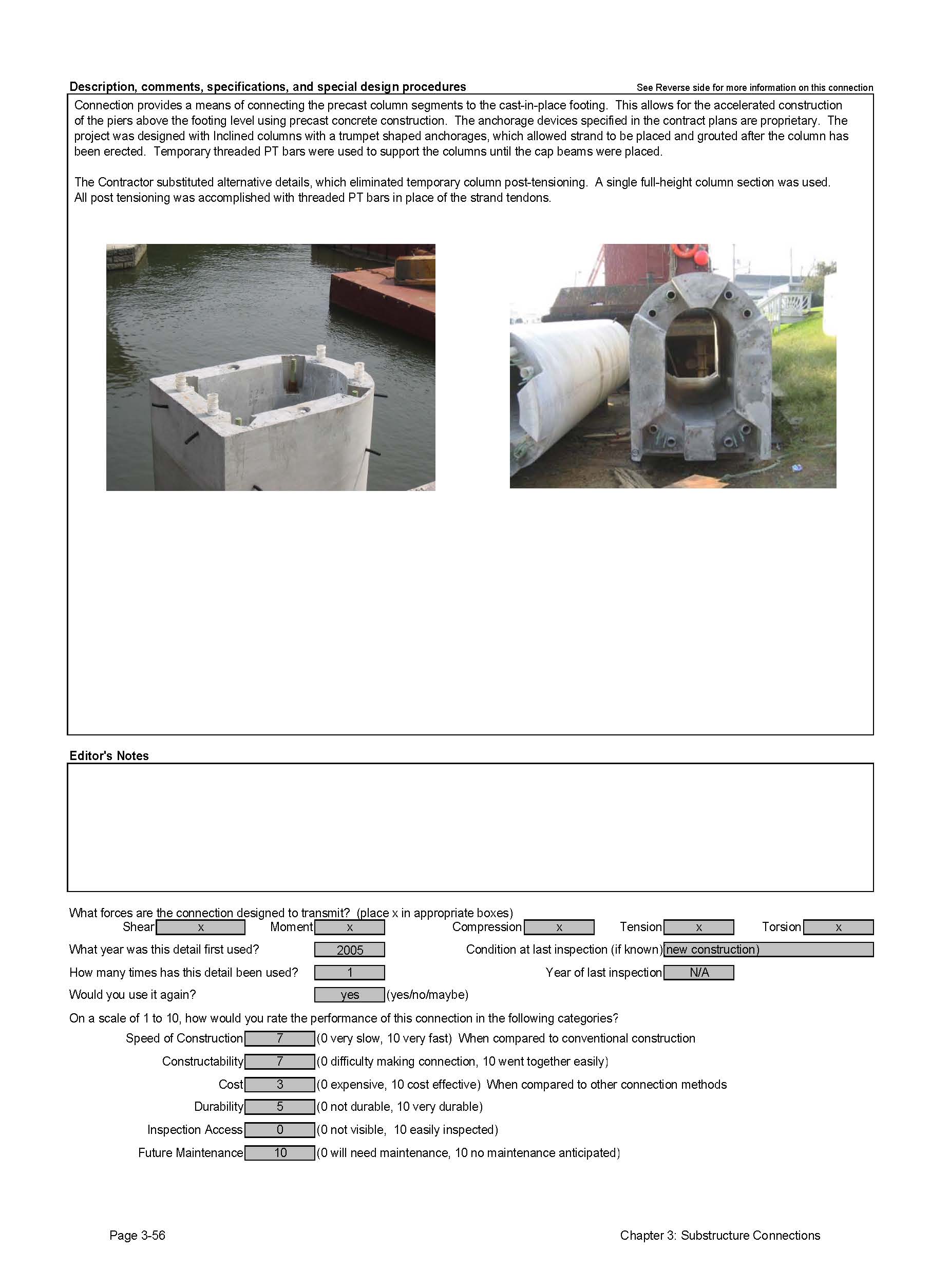
3.1.4.1 Connection to Cast-in-Place Concrete Footing
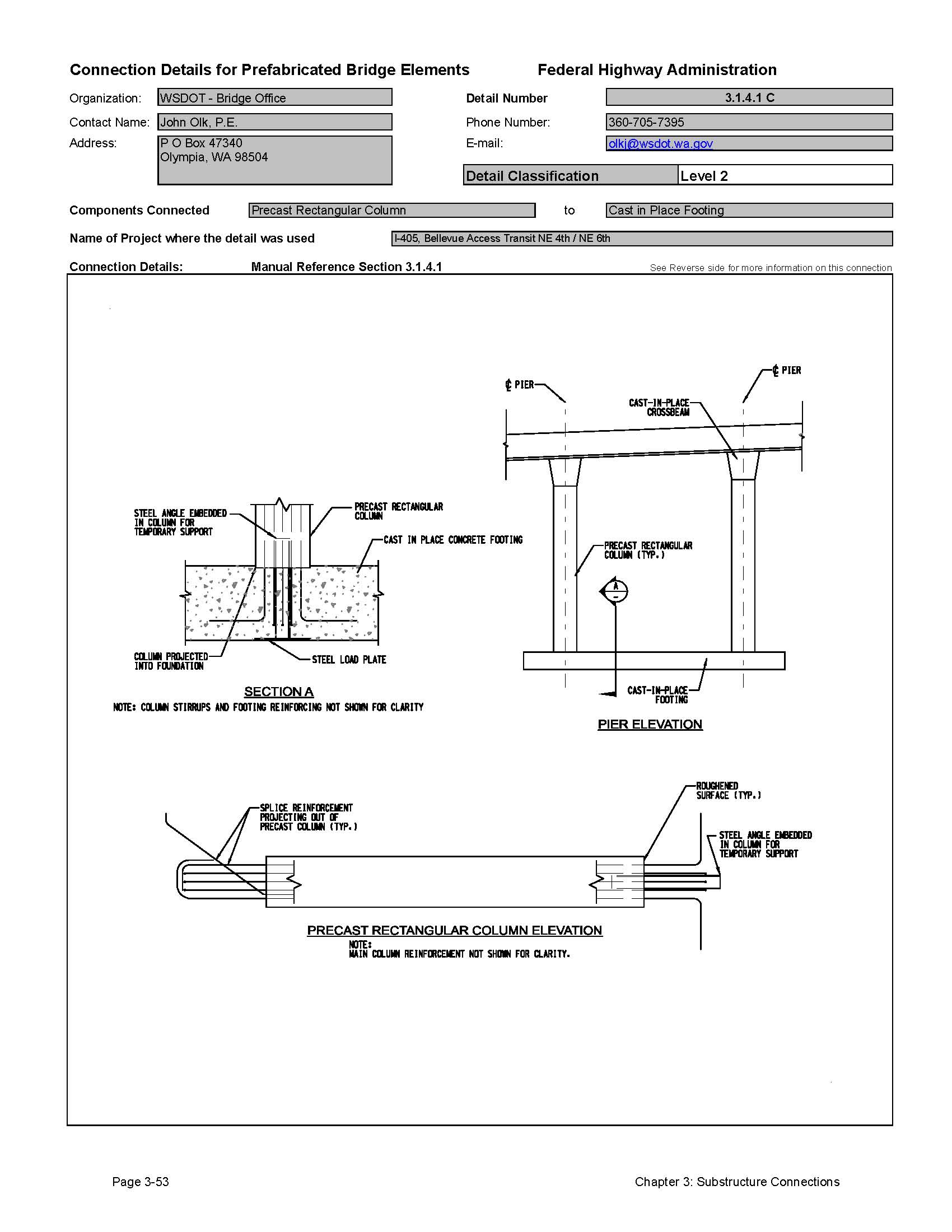
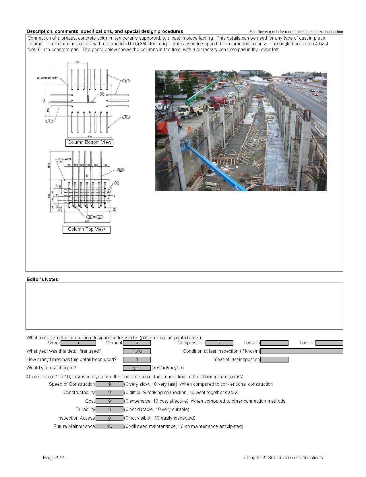
The connection of a precast pier column element to a cast-in-place concrete footing can be made using two approaches. The state of Washington developed a detail that involved casting the footing under the precast column element, which had reinforcing projecting from the base. The column was braced in position on top of a temporary support in the middle of the column. The footing was simply formed and poured around the projecting column reinforcement.
The second method of making this connection is by the use of mechanical connectors or post-tensioning. In this case, the location of the mechanical devices and/or post-tensioning needs to be carefully coordinated. Tolerances need to be established and specified so that the field fit-up is successful. See Section 1.7 for more discussion on tolerances.
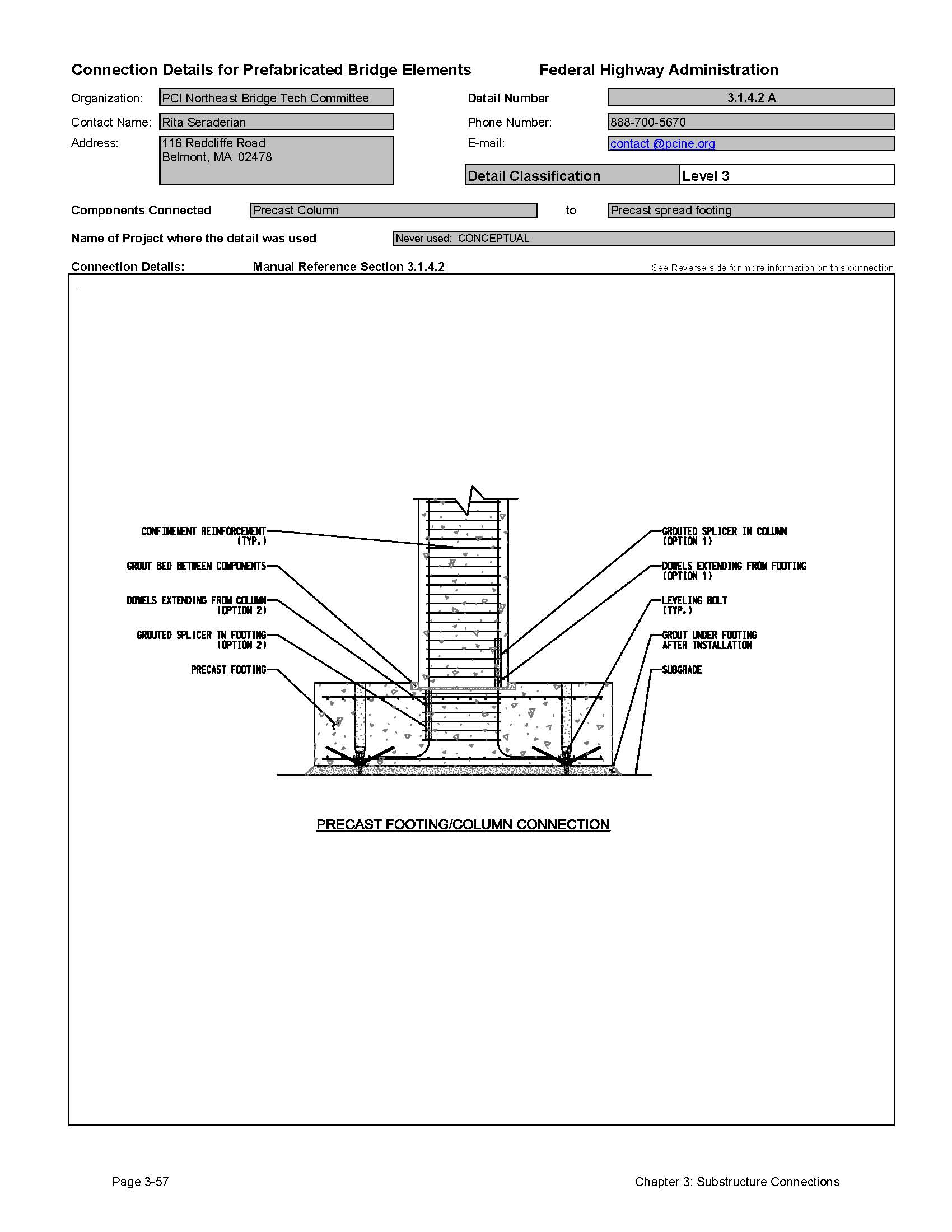
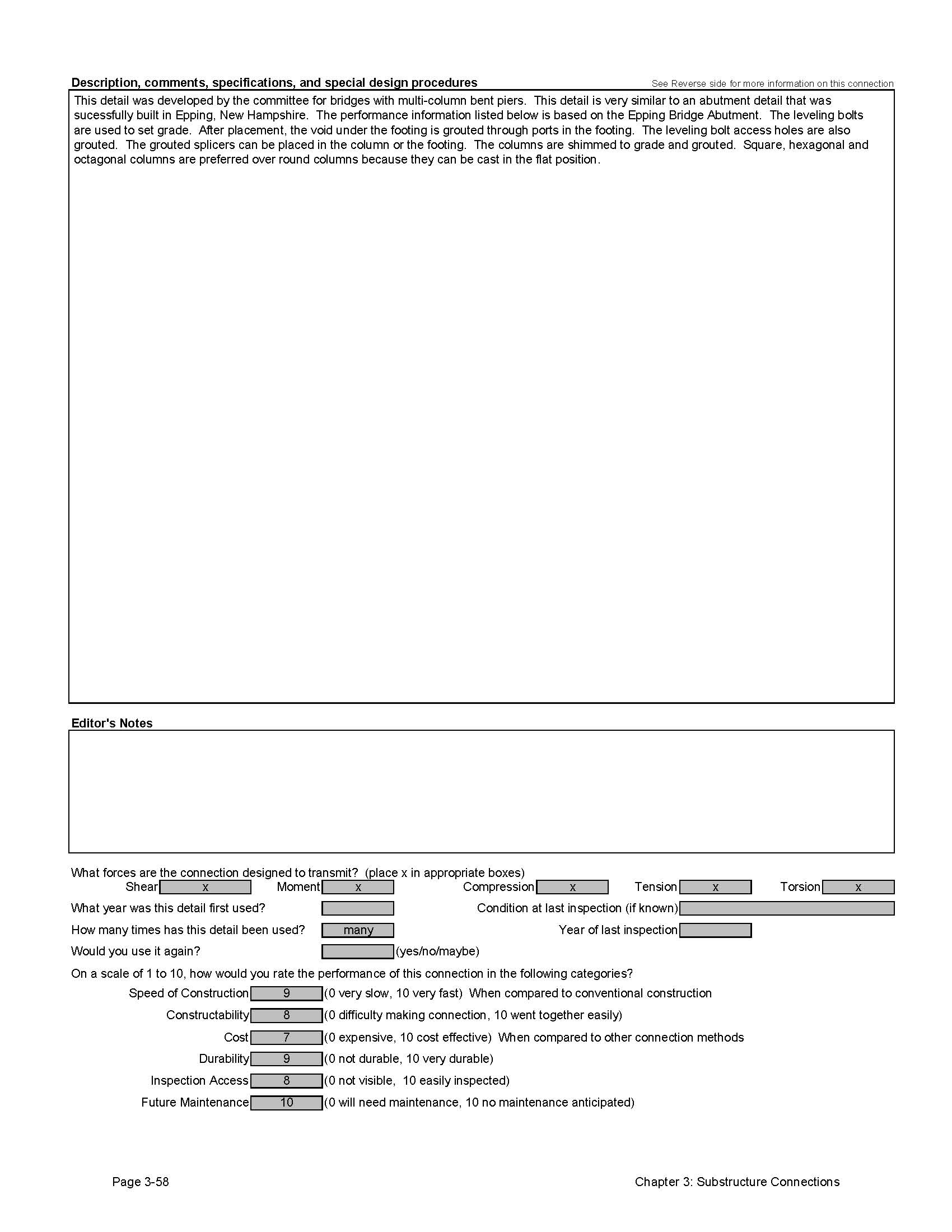
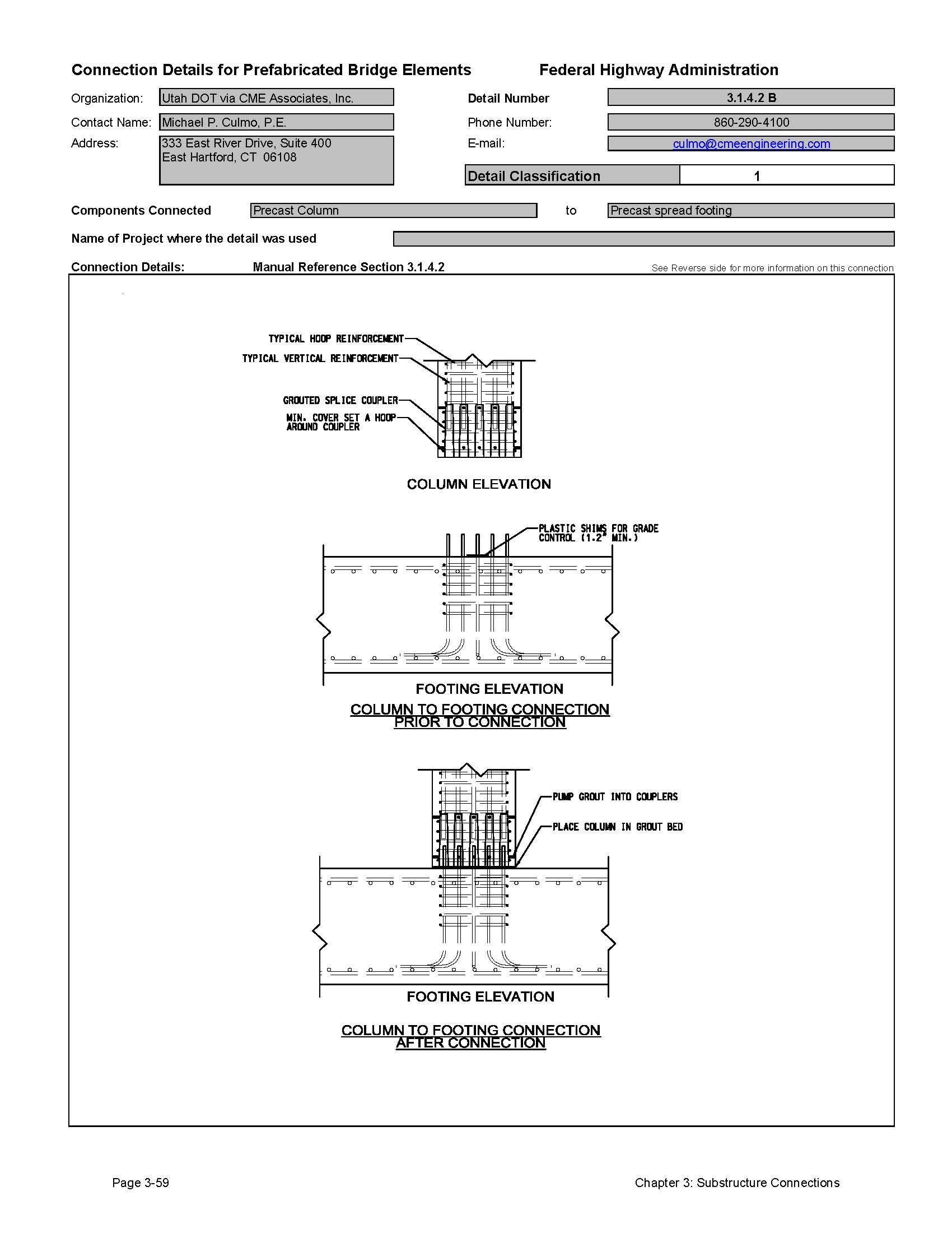
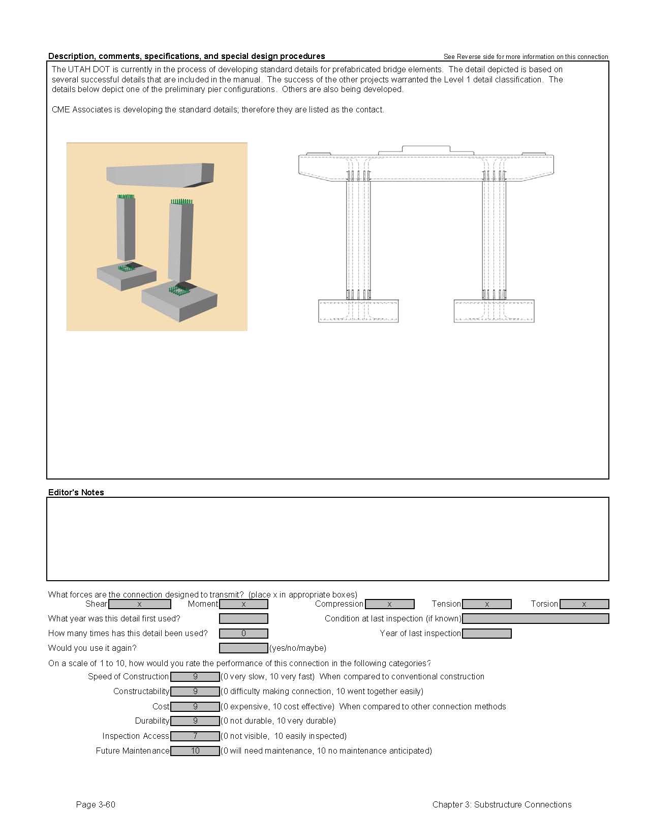
3.1.4.2 Connection to Precast Concrete Footing
To the knowledge of the authors of this manual, the connection of a precast column element to a precast footing element has not been used on a bridge project in the United States. Section 3.2.1.1 will discuss the connection of cantilever wall elements to precast footings (which has been used on at least one bridge project). This type of connection is essentially the same as a pier column connection, since it is called on to provide a moment splice.
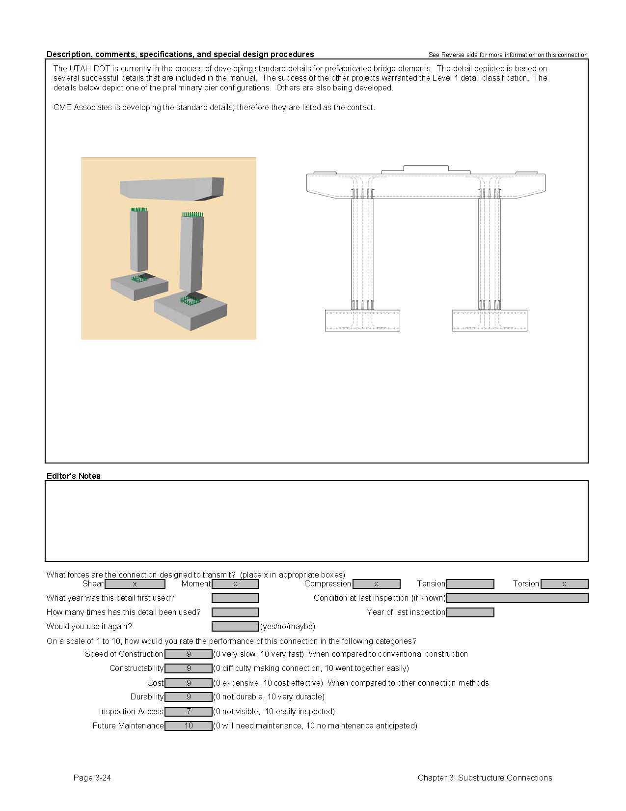
The Northeast States PCI Bridge Technical Committee has developed standard details for this connection that use grouted reinforcing splice couplers. These connections are based on details used in building and parking garage construction, where they have been used successfully. The detail has been classified as conceptual in this manual; however, based on the performance of abutment connections and its use in other industries; it should be a reliable and useful connection for piers.
As with any mechanical splice connection, the tolerances of the mechanical connectors need to be specified. See Section 1.7 for more discussion on tolerances.
3.1.5 Grade Control and Tolerances
The construction of prefabricated pier elements can lead to problems with grade and horizontal control. Minor grade and alignment problems can be corrected in other connections above the pier (haunches in deck pour forming for example); however it is always desirable to make adjustment for grade as the construction progresses. All of the connections shown in the manual have grout beds or cast-in-place closer pours which can be used to make minor adjustment to grade. This is commonly done by means of small shim packs that are placed between the elements being connected. Often these shims are made of polymer sheets and are left in place in the finished structure. Steel shims should be avoided because they would represent a hard point that may attract stresses as the structure is loaded, which could lead to spalling of the precast elements.
The use of mechanical connectors or post-tensioning requires more careful attention to tolerances in the precast process. Two things can be done to ensure proper fit-up in the field. If post-tensioning is specified, the connections can be match cast to minimize field fit-up problems. If grouted reinforcing splice couplers are used between two precast elements, the designer can specify that the connections be dry connected in the shop to ensure proper fit.
See Section 1.7 for more discussion on tolerances.
3.1.6 Evaluation of Performance and Long Term Durability of Prefabricated Pier Systems
The connections shown in the manual have proven to be quite durable. During the collection of data for this manual, several precast pier projects were identified that did not perform well. These involved the use of steel plate connectors in high corrosion environments.
To date, connections using grouted joints have performed very well. For example, the Edison Bridge in Lee County Florida has been in service for over 15 years and is in very good condition. The connections on this bridge are in one of the most severe environments in the country.
Several details included in this manual consist of exposed welded plate connections. These connections should either be used in non-corrosive environments, or coated after welding to prevent future corrosion.
3.1.7 Estimated Construction Time for Connections
Exact timelines for construction are dependent on a number of factors including site access, traffic control, weather, crane locations and storage areas. It is possible to make reasonable estimates on construction time for the various systems discussed in this section.
Table 3.1.7-1 contains approximate installation times for the various pier systems included in this section:
| System | Minimum Installation Time | Comments |
|---|---|---|
| Grouted Duct or Reinforcing Splice Coupler Connections | 1 Day or less | This includes bracing and grouting. |
| Blockout closure pour connections | 2 Days | Two days are required for the closure pour concrete (high early strength) to attain at least enough strength to allow for construction to progress. |
| Post-Tensioning Systems | 3 Days | This includes connecting the elements with epoxy, placement of the post-tensioning strand or rod, and grouting of the ducts. |
3.1.8 Recommendations for Improvements to Current Practices
To date, grouted connections and closure pour systems on precast piers have been very successful and durable. The one major hurdle that needs to be addressed is the development of pier connections in high seismic regions. Most of the connections presented in this manual are only applicable to low to moderate seismic regions where plastic hinging of column elements in not required until research proves otherwise. Research is underway to develop connections that can be used in high seismic regions.
3.1.9 Connection Detail Data Sheets for Pier Systems
The following pages contain data sheets for the various prefabricated pier systems. This information was primarily gathered from agencies that have developed and used the systems. Most data in the sheets were provided by the owner agency; the authors added text when an agency did not supply all requested information. The owner agencies also provide a comparative classification rating.
Each connection detail data sheet is presented in a two-page format. Users of this Manual can simply remove and copy a data sheet for use in developing a system for a particular project. These sheets are meant to give users a basic understanding of each connection that can be used during the type study phase of a project. The data sheets are not meant to be comprehensive, but do convey the component make-up of the detail, how it is meant to function, and provide some background on its field application. Users will need to investigate each connection further, consider site-specific conditions, and apply sound engineering judgment during design.
The key information provided for each connection is as follows:
- Name of the organization that supplied the detail
- Contact person at the organization
- Detail Classification Level
- Level 1
This is the highest classification level that is generally assigned to connections that have either been used on multiple projects or have become standard practice by at least one owner agency. It typically represents details that are practical to build and will perform adequately. - Level 2
This classification is for details that have been used only once and were found to be practical to build and have performed adequately. - Level 3
This classification is for details that are either experimental or conceptual. Details are included in this Manual that have been researched in laboratories, but to the knowledge of the authors, have not been put into practical use on a bridge. Also included in this classification are conceptual details that have not been studied in the laboratory, but are thought to be practical and useful.
- Level 1
- Components connected
- Name of project where the detail was used
- Manual Reference Section
- The section(s) of this Manual applicable to the particular detail shown.
- Connection Details
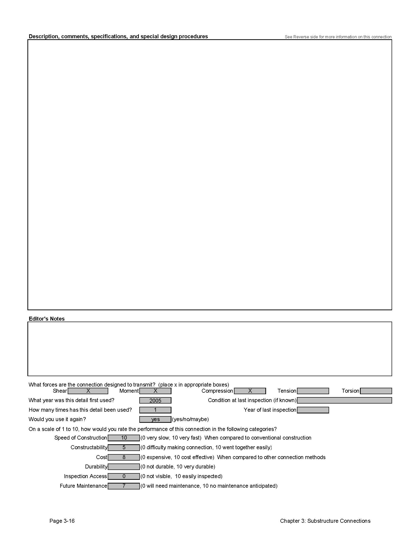
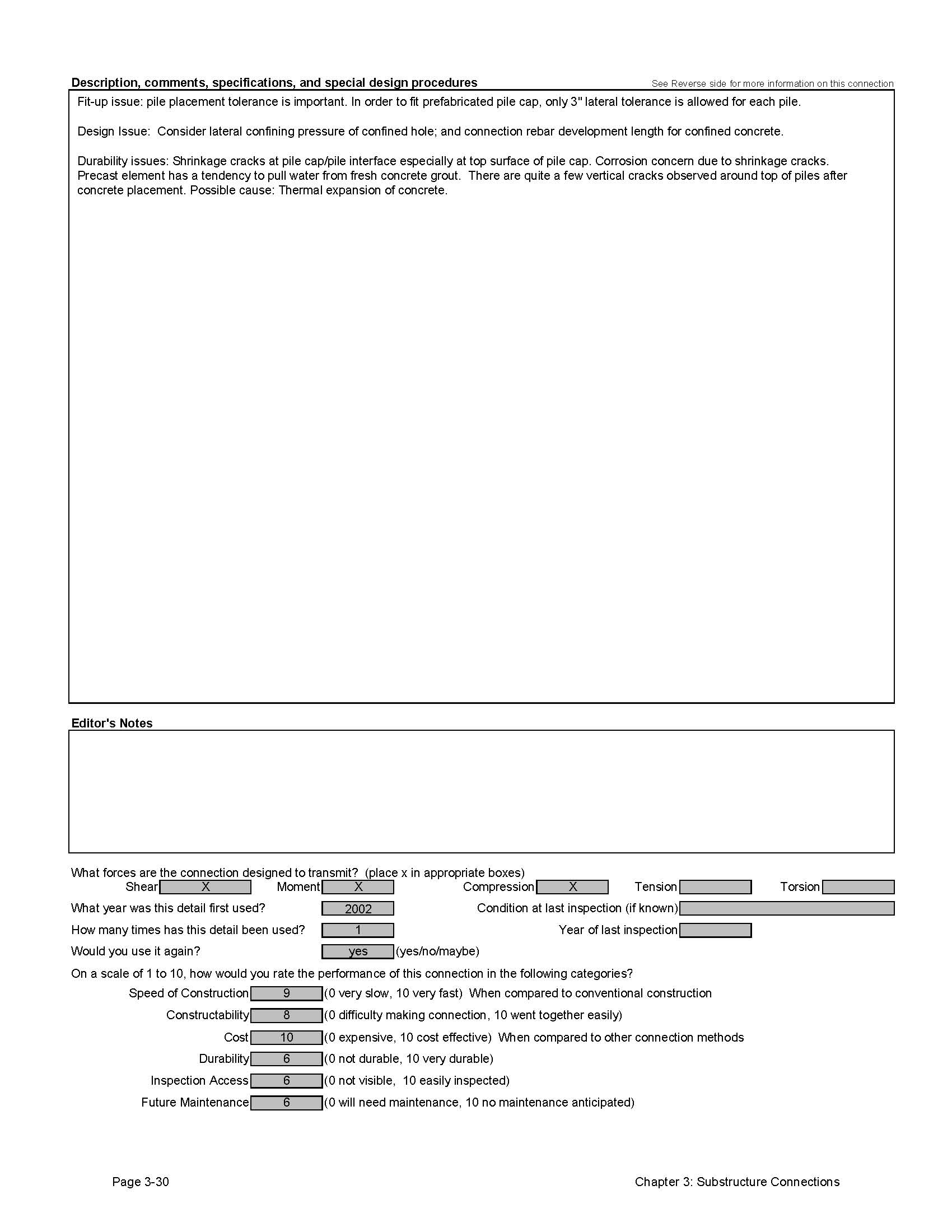
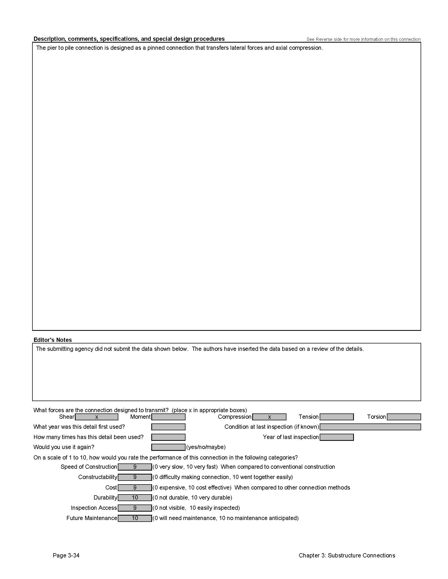
- Description, comments, specifications and special design procedures
- Forces that the connection is designed to transmit
- Information on the use of the connection (including inspection ratings)
- A performance evaluation of the connection rated by the submitting agency
Click images below to enlarge
Detail 3.1.1.1A

Detail 3.1.1.1B
Detail 3.1.1.1C
Detail 3.1.1.1D
Detail 3.1.1.2A
Detail 3.1.1.2B

Detail 3.1.1.2C
Detail 3.1.1.2D
Detail 3.1.1.3A

Detail 3.1.1.3B


Detail 3.1.1.4A
Detail 3.1.1.4B
Detail 3.1.1.4C
Detail 3.1.1.4D
Detail 3.1.1.4E
Detail 3.1.1.4F
Detail 3.1.1.5A

Detail 3.1.2.1A
Detail 3.1.2.1B

Detail 3.1.3.1A

Detail 3.1.4.1A
Detail 3.1.4.1B
Detail 3.1.4.1C
Detail 3.1.4.1D
Detail 3.1.4.2A
Detail 3.1.4.2B
| << Previous | Contents | Next >> |