

| << Previous | Contents | Next >> |
Connection Details for PBES
Chapter 4 - Foundation Connection
This chapter is devoted to connections in foundation systems. The chapter has been broken out into typical foundation elements that are used on most bridges. The AASHTO LRFD design specifications [1] define constructed foundations as spread footings, driven piles and drilled shafts.
4.1: Footing and Pile Systems
Few states have designed and constructed prefabricated footings for bridges, while most states use prefabricated piles. The New Hampshire DOT has had success with prefabricated footings. The Northeast PCI Bridge Technical Committee has adopted these details as a standard for the northeast region.
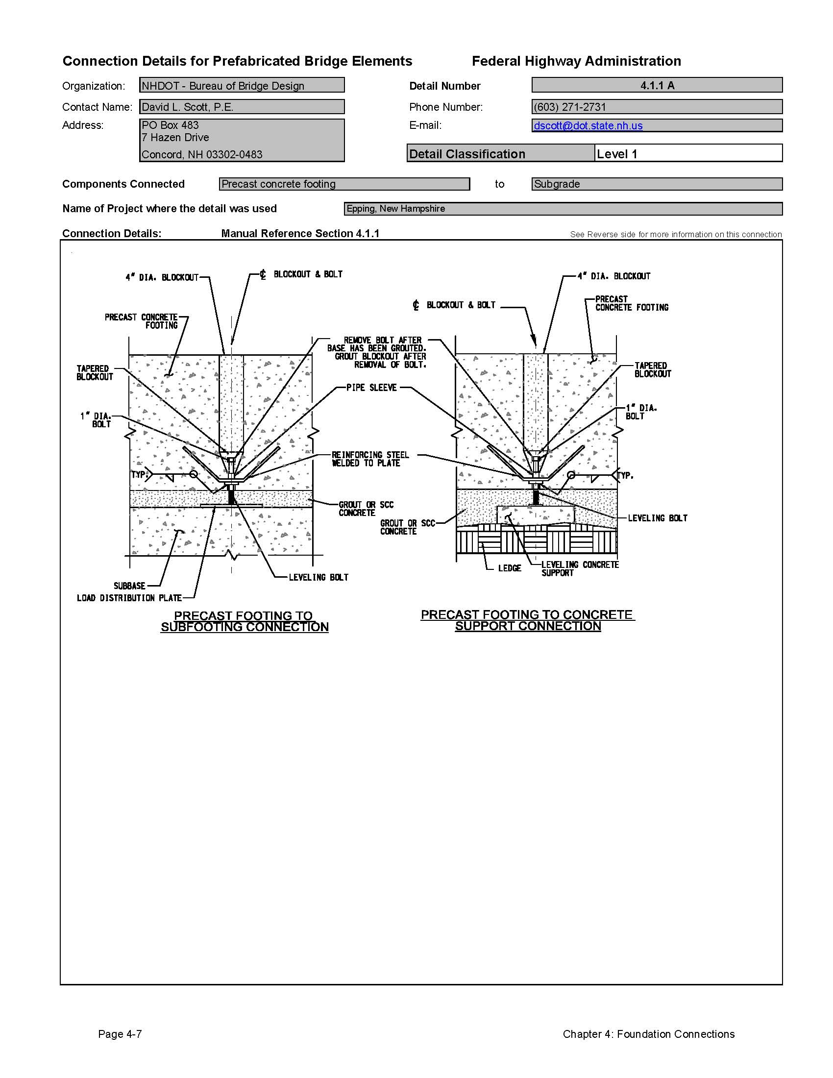
4.1.1 Precast Footing to Subgrade Connections
One of the primary difficulties with using precast concrete footings is the ability to properly seat the footing on the subgrade. Inadequate seating will result in rocking of the footings and settlement of the foundation.
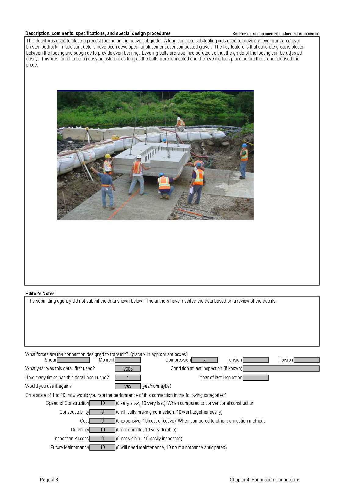
In order to eliminate this problem, it is necessary to place a flowable concrete or grout under the footing. The New Hampshire DOT has developed a detail that includes leveling bolts that lift the footing above the subgrade material and allows for the installation of flowable grout. The flowable grout can either be a low grade concrete, or even flowable fill. High strength material is not required for the fill because the material is simply a filler, and the footing bearing pressures are normally in the order of 50 psi.
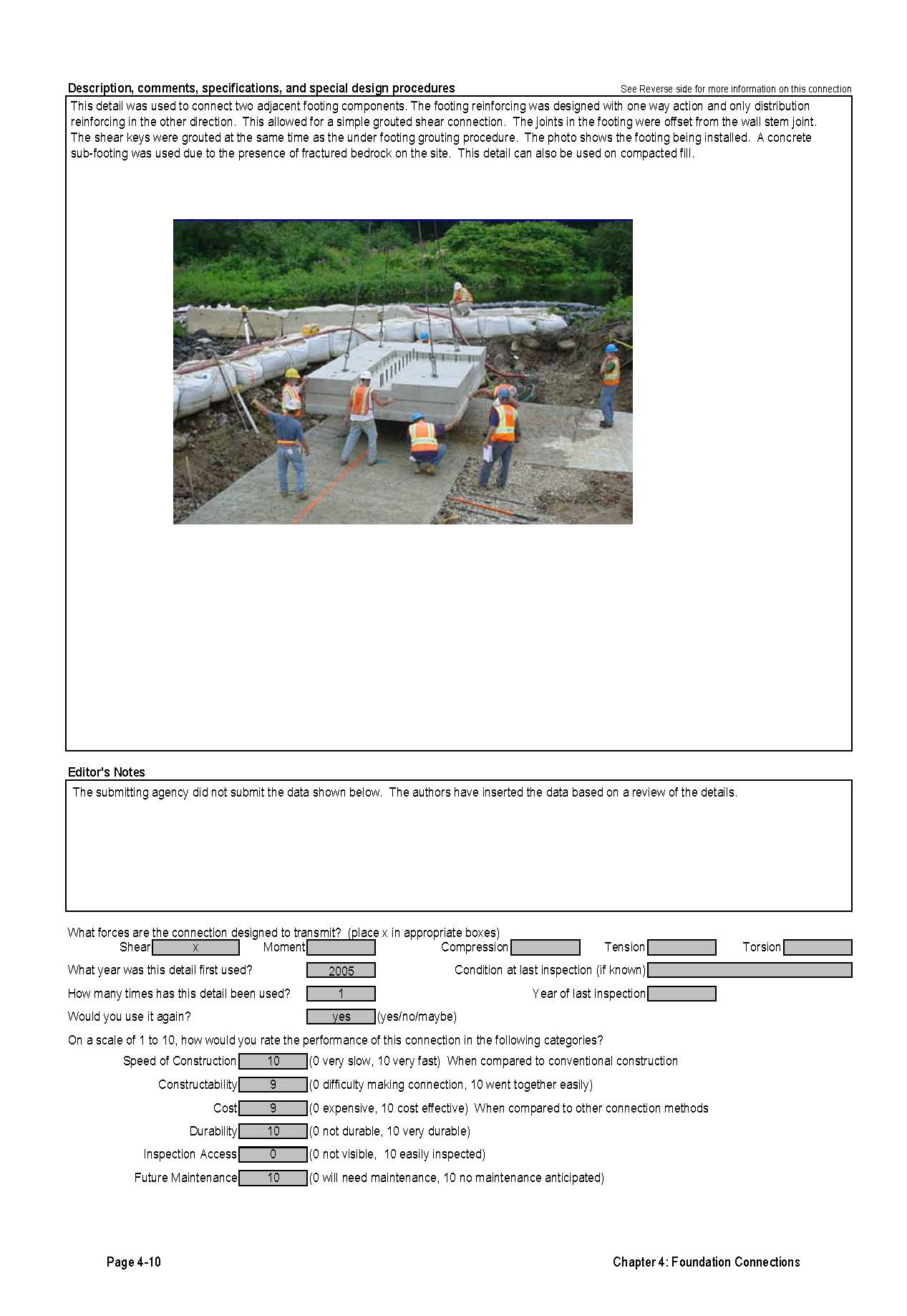
For footings constructed on bedrock, it is recommended that a sub-footing be poured to provide a relatively level area for setting the footings. When a footing is placed on soil, the footings can be placed on steel plates under the leveling bolts.
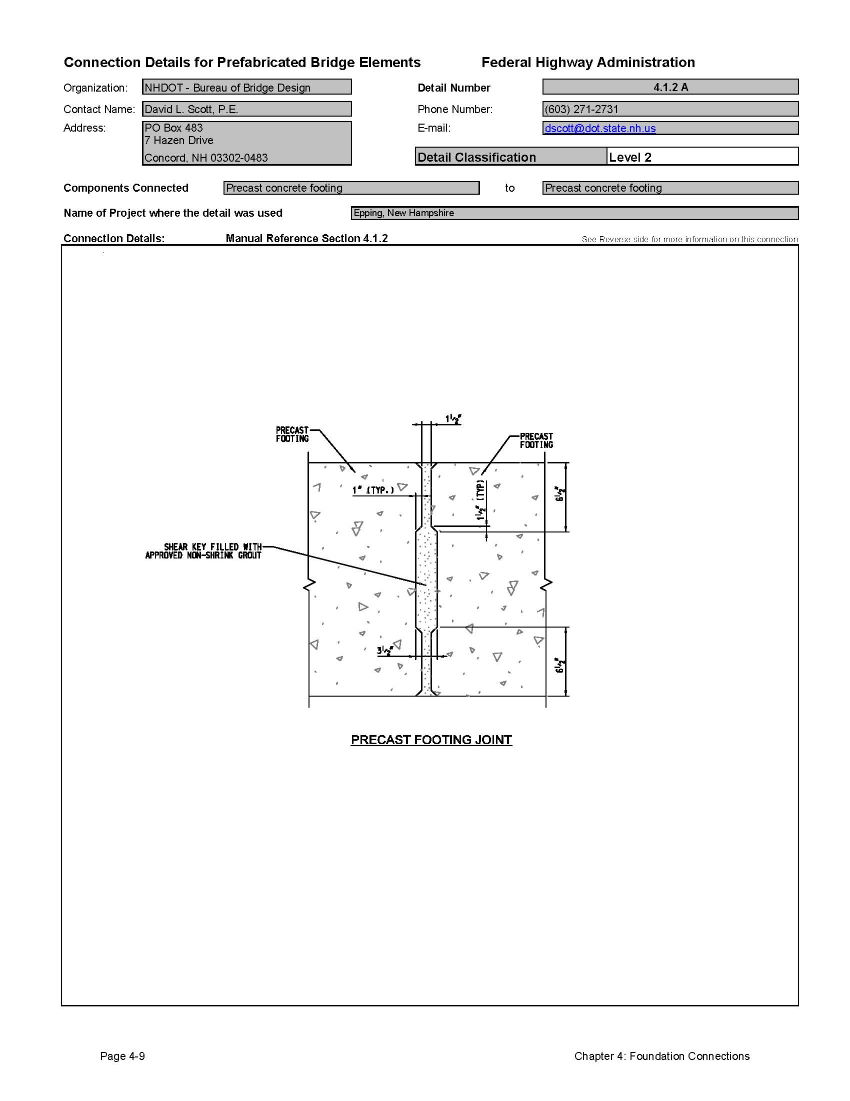
4.1.2 Precast Footing to Precast Footing Connections
Depending on the design of the footing, the connection between adjacent footing elements may or may not need to be a structural connection. Abutment and wall footings are primarily designed as one way slabs. This means that discrete footing elements can be placed without a significant connection. The New Hampshire DOT has developed a detail where the footings are connected with a simple grouted shear key.
If a more substantial moment connection is desired, a small closure pour is recommended. Reinforcing steel can be projected from each footing elements with a simple lap splice between the bars. This closure pour is easy to form and pour because the two footing elements and the subgrade can be used for most of the formed area.
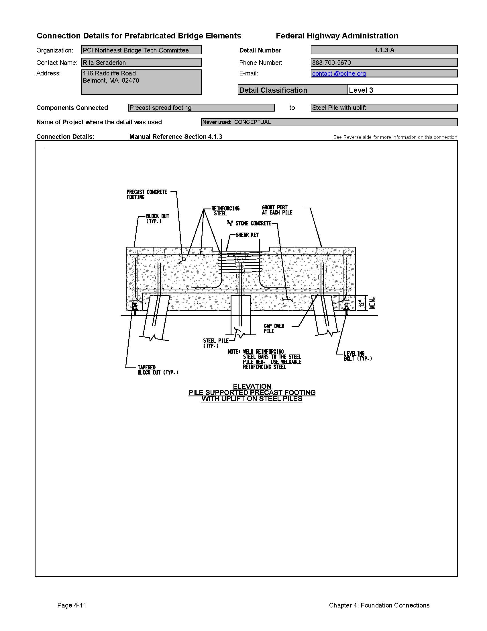
4.1.3 Precast Footing to Steel Pile Connection
Several states have developed details for connecting precast concrete pier caps to steel pile when used as a pier bent (see Section 3.1.1.3). Some of these details could be used for footing connections also. There Page 4-1 Chapter 4: Foundation Connections has also been steel pile connection details developed for integral abutment bridges (see Section 3.2.3).
The Northeast PCI Bridge Technical Committee has developed conceptual details for the connection of a spread footing to steel piles. While these details are conceptual, they are based on details that are similar to the pier cap connections.
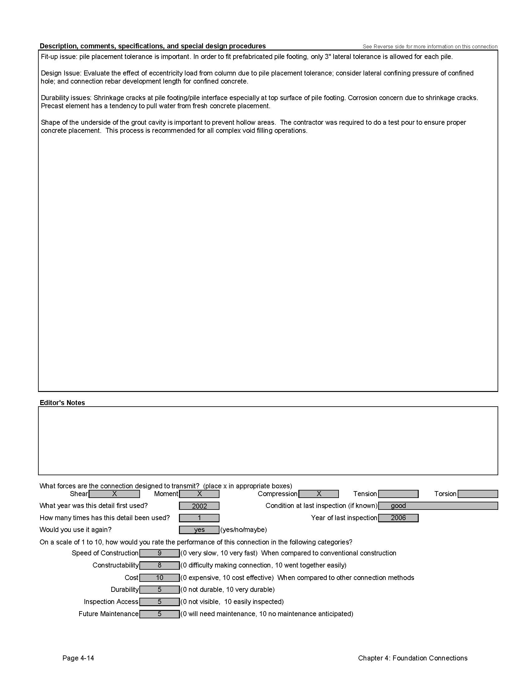
The major issues with a pile to footing connection are whether or not there is anticipated uplift on the piles or if there is a need to provide moment capacity in the pile connection. Uplift capacity can be achieved by welding reinforcing steel to the pile end and embedding the reinforcing in a closure pour (note that weldable reinforcing steel will be required for this connection). Moment capacity is achieved by embedding the pile top at least 12 inches into the footing.
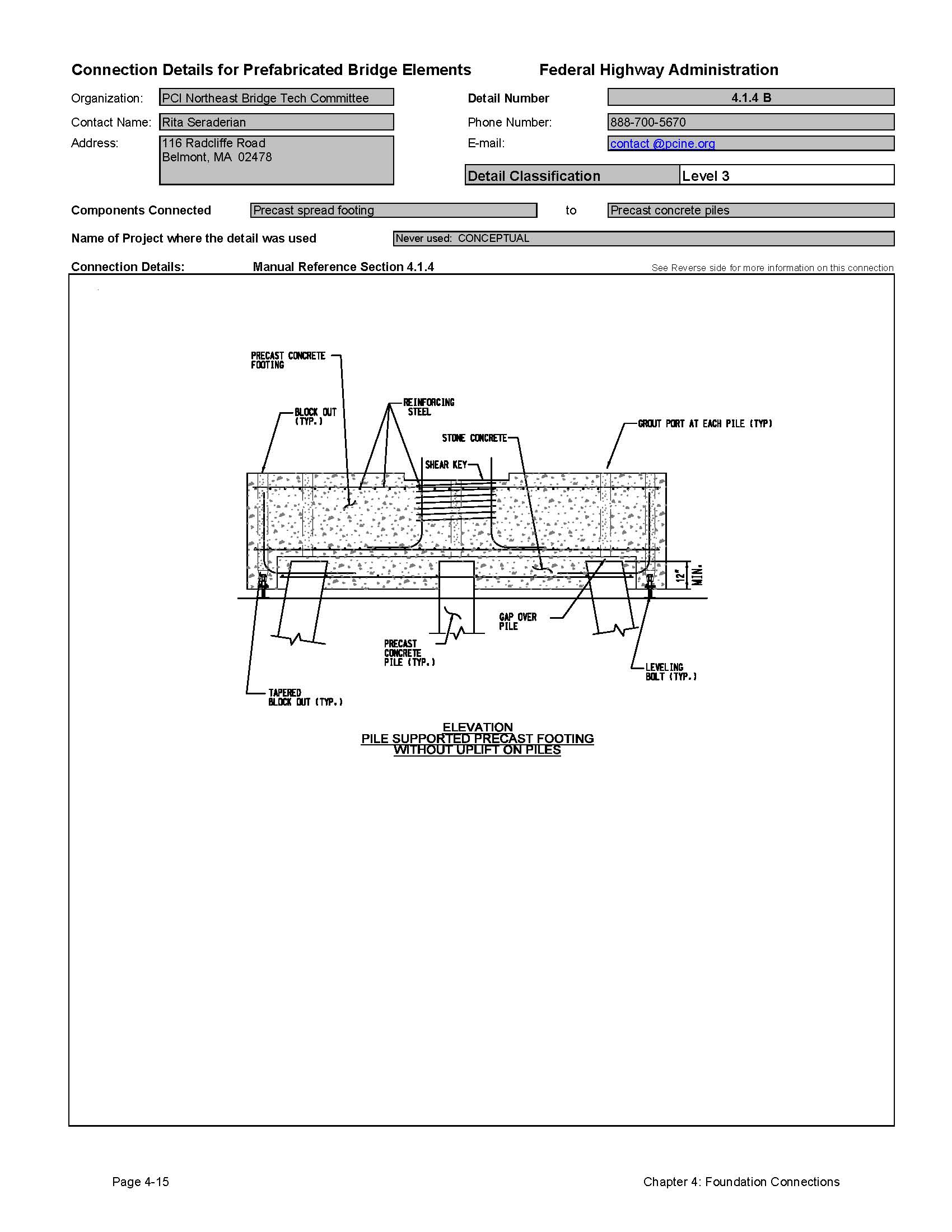
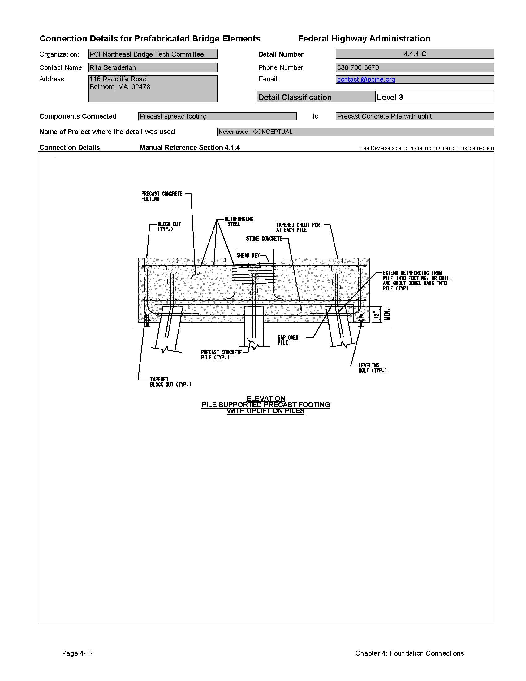
4.1.4 Precast Footing to Precast Concrete Piles
As with the steel pile connections described above, several states have developed connection details for precast concrete piles connected to precast concrete pier bents. There have also been concrete pile connection details developed for integral abutment bridges (see Section 3.2.3).
The Florida DOT has developed a connection of a hollow precast concrete pile to a precast footing. This connection consists of a large blockout in the footing where a reinforcing steel cage can be installed between the pile top and the blockout. This connection can develop the full moment capacity of the pile. The Northeast PCI Bridge Technical Committee has also developed conceptual details for the connection of a spread footing to precast concrete piles.
4.1.5 Precast Footing to Cast-in-place Pile or Drilled Shaft Connections
To the knowledge of the authors, no state has developed a connection detail for cast-in-place piles or drilled shafts connected to precast concrete footings. The details discussed in Section 4.1.4 could easily be adapted for use with cast-in-place concrete piles or drilled shafts.
4.1.6 Precast Pile to Precast Pile Connection
Most precast concrete driven piles are square, round, or octagonal solid piles. Many states used this pile and have standard details for connecting piles that need to be spliced. The precast concrete pile industry has developed standard pile splicing details. The PCI manual entitled Precast Prestressed Concrete Piles (BM-20-04) [50] is recommended for more information on this subject.
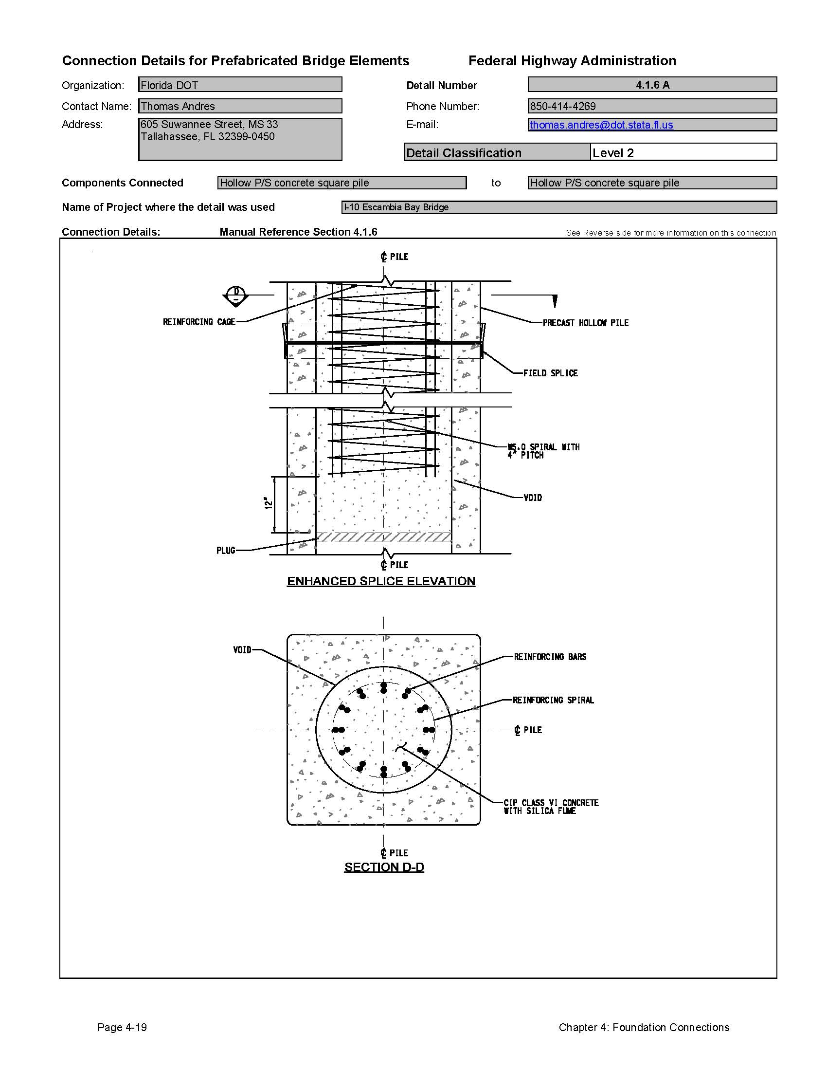
The Florida DOT has developed a detail for splicing hollow square prestressed concrete piles. This detail consists of a reinforced concrete closure pour between pile elements.
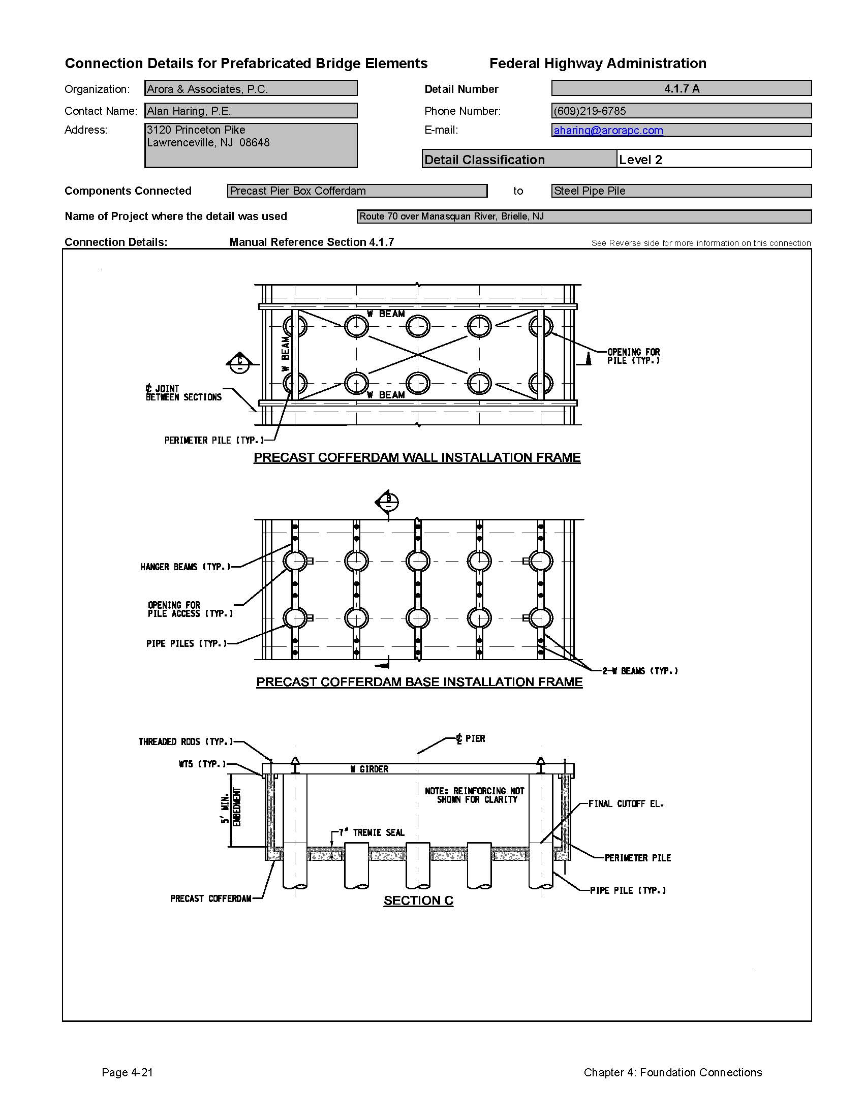
4.1.7 Precast Pier Box Cofferdams
One of the most difficult processes for construction of piers over water involves the construction of the pier footings on piles. This can involve complicated sheeting systems and cofferdams. The advent of larger diameter drilled shaft technology has brought about new methods for supporting bridge structures over water. With large diameter drilled shafts, it is possible to support large bridges with a few or even one drilled shaft per pier column.
Several projects have been designed where a precast concrete pier box was used to dewater the area where the drilled shaft connects to the bridge footing. For example, the new Providence River Bridge in Providence, Rhode Island, has precast concrete pier boxes that were hung from the 8 foot diameter drilled shafts that allowed the construction of the footings in the dry. The precast box was set over the drilled shaft and sealed with a small tremie pour around the drilled shaft. These systems can eliminate the need for complicated deep cofferdams and dewatering systems, especially in deep water. When built using HPC, the precast box forms can serve as an additional corrosion protection system for the new pier footing.
Figure 4.1.7-1 Providence River Bridge Pier Box
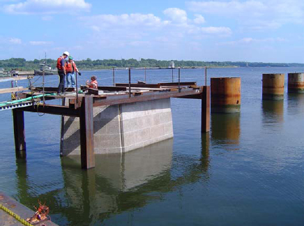
Figure 4.1.7-2 Providence River Bridge Pier Box
Preparation for Footing Reinforcing Placement
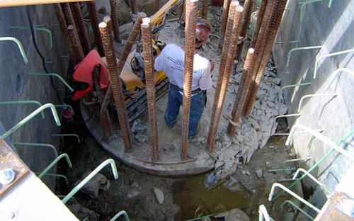
Figures 4.1.7-1 and 2 show the construction of the Providence River Bridge. The use of the precast concrete pier boxes saved the contractor significant time in the construction of the foundations.
4.1.8 Grade Control and Tolerances
The grade and alignment of prefabricated foundation elements should be controlled as much as possible, since it may be difficult to make significant adjustments in other parts of the structure.
The placement of precast footing elements can be adjusted by shims during placement. The New Hampshire DOT installed leveling bolts in the footings that allow precise adjustment of the footing during installation. This system worked well, although there was some difficulty in turning the leveling bolts. This was attributed to corrosion of the bolt threads. They corrected this by greasing the bolts and by adjusting the bolts prior to full release of the footing from the crane.
4.1.9 Evaluation of Performance and Long Term Durability of Prefabricated Footing and Pile Systems
To date, very few prefabricated footing systems have been constructed. The oldest installation is on the Escambia Bay Bridge in Florida. This footing is in a severe corrosion environment and is still in good condition.
Based on the performance of other precast foundation systems (piers, abutments) which have similar details, it is likely that the precast footing systems will be very durable.
4.1.10 Estimated Construction Time for Connections
Exact timelines for construction are dependent on a number of factors including site access, traffic control, weather, crane locations and storage areas. It is possible to make reasonable estimates on construction time for the various systems discussed in this section.
Table 4.1.10-1 contains approximate installation times for the various foundation connection systems included in this section:
| System | Minimum Installation Time | Comments |
|---|---|---|
| Precast footing to subgrade | 1-2 Days | This includes installation leveling and grouting. |
| Precast footing to precast footing | 1-2 Days | One day for a grouted shear key, 2 days for a concrete closure pour. |
| Precast footings to various piles | 1-3 Days | This includes placement and grouting. |
| Precast Pile to Precast Pile | 1 day | |
| Precast concrete pier boxes | 1-4 weeks | This includes the installation of the box and dewatering (not footing placement). This depends greatly on the size of the pier and the complexity of the footing. |
4.1.11 Recommendations for Improvements to Current Practices
Prefabricated footings have not been used by many states. This is probably because of concerns about obtaining a proper connection to the subgrade materials. The work completed by several states should be expanded to more projects so that a more substantial knowledge base will be developed.
4.1.12 Connection Detail Data Sheets for Footing and Pile Systems
The following pages contain data sheets for the various prefabricated foundation systems. This information was primarily gathered from agencies that have developed and used the systems. Most data in the sheets were provided by the owner agency; the authors added text when an agency did not supply all requested information. The owner agencies also provide a comparative classification rating.
Each connection detail data sheet is presented in a two-page format. Users of this Manual can simply remove and copy a data sheet for use in developing a system for a particular project. These sheets are meant to give users a basic understanding of each connection that can be used during the type study phase of a project. The data sheets are not meant to be comprehensive, but do convey the component make-up of the detail, how it is meant to function, and provide some background on its field application. Users will need to investigate each connection further, consider site-specific conditions, and apply sound engineering judgment during design.
The key information provided for each connection is as follows:
- Name of the organization that supplied the detail
- Contact person at the organization
- Detail Classification Level
- Level 1
This is the highest classification level that is generally assigned to connections that have either been used on multiple projects or have become standard practice by at least one owner agency. It typically represents details that are practical to build and will perform adequately. - Level 2
This classification is for details that have been used only once and were found to be practical to build and have performed adequately. - Level 3
This classification is for details that are either experimental or conceptual. Details are included in this Manual that have been researched in laboratories, but to the knowledge of the authors, have not been put into practical use on a bridge. Also included in this classification are conceptual details that have not been studied in the laboratory, but are thought to be practical and useful.
- Level 1
- Components Connected
- Name of Project where the detail was used
- Manual Reference Section The section(s) of this Manual applicable to the particular detail shown.
- Connection Details
- Description, comments, specifications and special design procedures
- Forces that the connection is designed to transmit
- Information on the use of the connection (including inspection ratings)
- A performance evaluation of the connection rated by the submitting agency
Click images below to enlarge
Detail 4.1.1A
Detail 4.1.2A
Detail 4.1.3A

Detail 4.1.4A

Detail 4.1.4B
Detail 4.1.4C
Detail 4.1.6A
Detail 4.1.7A
| << Previous | Contents | Next >> |