

Prefabricated Bridge Elements and Systems in Japan and Europe
Scan Team Implementation Plan
Rev 10/25/04
Background
In April 2004, eleven US engineers from the FHWA, State DOTs, local agency, private industry, and academia participated in a Prefabricated Bridge Elements and Systems Scan Tour of Japan and four European countries. The scan was jointly sponsored by FHWA and AASHTO. The purpose of the tour was to investigate and document the applications and experiences with prefabricated bridge systems in Japan and Europe. The panel conducted meetings with government agencies, academia, and private sector organizations. The tour resulted in a number of significant strategic findings.
The Scanning Team's primary objective was to: Identify the most significant technologies for implementation in the United States.
The Team visited Japan, the Netherlands, Belgium, Germany, and France. The following activities were undertaken:
- Evaluate the performance of prefabricated bridges
- Interview owners, designers, fabricators, and contractors on project experiences and lessons learned
- Evaluate documentation and reports
- Report on bridge elements/systems and connection details
The focus areas of the scan were prefabricated bridge elements and systems that:
- Minimize traffic disruption (congestion)
- Improve work zone safety
- Minimize environmental impact
- Improve constructibility
- Increase quality
- Lower life-cycle costs
The Scanning Team identified 10 technologies for implementation in the US. The intended audience for these technologies include: AASHTO Standing Committee on Highways; Subcommittees for Bridges and Structures, Materials, Construction, and Maintenance; Transportation Research Board; National Association of County Engineers (NACE); Associated General Contractors (AGC); American Road and Transportation Builders Association (ARTBA); Local Technical Assistance Program (LTAP) centers; and national bridge conferences' attendees in 2004-2005.
Each of the ten Implementation Items lists a "Scan Team Lead". These are the team members most responsible for promoting the particular technology during the implementation phase. Their responsibilities include:
- Serve as the first contact for DOT and consultant engineers regarding questions on the technology.
- Contact other countries and obtain drawings, test reports, specifications, and other information as needed to facilitate implementation by owners.
- Ensure research is initiated or existing research obtained for Implementation Items that have been identified as needing further study.
- Represent the Scan Team at workshops demonstrating the technology.
- In general, act as an advocate for the Implementation item.
The technologies are categorized into four sections which are Bridge Movement Systems, Superstructure Systems, Deck Systems, and Substructure System.
Bridge Movement Systems
Implementation Item: Self Propelled Modular Transporters (SPMTs)
Countries:
- Netherlands - Mammoet Europe/Mammoet USA, Inc. http://www.mammoet.com/.
- Belgium - Sarens NV http://www.sarens.com/.
- Various Projects in European countries.
Background: The Scanning Team visited the firms of Mammoet and Sarens in the Netherlands and Belgium respectively. Both firms specialize in heavy lifting and provide service to customers in the petroleum, power, and heavy civil construction industries. Numerous European projects were presented by the two firms that showcased the versatility of SPMTs in lifting, transporting, rotating and setting or removing bridges. The bridge structure types included rigid frames, concrete box girders, culverts, steel tied arches and trusses, and steel girders. Lifting weights ranged from 500 to 5000 metric tons (550 to 5500 tons). The computer control systems for the SPMTs compensate to equalize loads between transporters and adjust height for uneven ground.
The Scanning Team was impressed by the opportunity this technology offers in minimizing traffic disruptions, improving work zone safety, and improving constructibility. The technology is being employed frequently by highway and railway companies to reduce construction impacts to operating facilities to days or hours rather than the several months required by traditional methods. With SPMTs the common approach is to construct the superstructure or total bridge off alignment without disrupting existing traffic. When complete, the SPMTs transport the completed structure into position with a traffic interruption ranging from several hours to a weekend if site preparation or foundation work is required.
Both Mammoet and Sarens have equipment in North America.
Strategy: The Scanning Team Implementation will consist of the following:
- Present the SPMT technology at meetings and conferences of AASHTO (including SCOH and its subcommittees and State DOTs), AGC, ARTBA, and TRB scheduled in 2004 and 2005.
- Present articles and papers to LTAP and various trade and engineering journals.
- Develop Project Planning Guide for owners including project selection criteria for use of SPMTs and emphasizing the necessity for early project planning, and adequate Right-of-Way needs for construction.
- Prepare draft specifications based on sample project specifications provided to the Scanning Team for states to consider in their projects. The intent is to detail the required qualifications for lifting contractors and reasonable tolerances for placement and distortions of the structure being moved.
- Solicit pilot projects for 2005/2006. Conduct workshops in association with the projects. Invite AASHTO States and FHWA to attend.
- Include information - descriptions, photos, drawings and specifications - on the variety of bridge projects observed by the Scan Team on the FHWA Prefabricated Website. This will serve as a resource to bridge designers and a stimulus to creatively consider alternatives to conventional construction.
Scan Team Lead: Mary Lou Ralls, Harry Capers, Ben Tang
Deliverables:
- Various presentations, articles, and papers.
- Project Planning Guide and Draft Specifications for contractor qualifications, lifting tolerances, and distortion.
- Descriptions, photos, drawings and specifications posted or linked from FHWA website, to display the variety of projects and methods employed to install bridges constructed off alignment.
- Candidate projects solicited through Federal program funding.
- Workshops to showcase the demonstration projects.
Timeframe: FHWA Website update: November 1, 2004.
Draft specifications: January 1, 2005.
Pilot projects and workshops: 2005 to 2006.
Funds Required: $25,000 for preparation of the draft specifications. It is anticipated a consultant will be utilized for this effort.
Up to $15,000 (approximately 15 @ an average of $1,000 each) to assist state bridge engineers who are planning potential projects to attend 2005-2006 workshops. The host state would have an additional $5,000 available to offset the cost of conducting the workshop. The funding will come from STIP funds.
States that contract for projects involving technology will likely be able to obtain Federal program funds, including IBRD and Highway for Life, to offset a portion of the project costs.
Implementation Item: Other Bridge Installation Systems (Launching, Floating, Skidding, Lifting or Rotating, the Prefabricated System into Position)
Countries: Japan, Germany, and France
Background: The Scanning Team toured construction sites and/or received presentations on projects involving a variety of innovative bridge installations methods. Japan, Germany and France were using several installation schemes to minimize the impact on existing highway or rail traffic, minimize environmental impacts, or improve work zone safety. Examples include:
Japan: Aritas Expressway Route 23/Isewangan Expressway- Longitudinally launching of a steel twin box girder superstructure with orthotropic deck. The rate of launching was 12 hours per 130-meter (425 ft) span. Total length was 724 meters (2375 ft) with a weight of 12,000 M tons (13,200 tons).
Japan: Aritas Expressway Route 23 - Transverse launch of a steel two span, four girder superstructure, weighing 3300 M tons (3600 tons). The lateral launch was 52 meters (170 ft)and the orthotropic deck was attached.
France: Risle River Highway Viaduc - Launching longitudinally, and from both abutments, a multi-span curved steel twin plate girder superstructure.
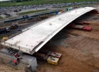
France: St. Pierre du Vauvray Project- Constructing a dry dock, fabricating the bridge, flooding the dry dock, and then floating the 855 M ton (940 tons) single span frame into place.
France: RR Bridge PRA 3265 in Normandy - Skidding a reinforced concrete, four span, 3300 M ton (3600 tons) structure into place using strand jacks.
France: Viaduc de Ventabren- Constructing a balanced cantilever segmental box parallel to existing traffic and then rotating the 2400 M ton (2640 tons) superstructure into final position.
The Scanning Team was impressed by the variety of methods employed. Particularly interesting was the philosophical approach of the French National Railway (SNCF) for their high volume corridors. SNCF stated their preferred method of bridge construction is to build off alignment and move the structure into position with only a 2- to 3-day interruption of service. Launching, floating, skidding, or rotating would be utilized dependent on the site requirements.
A limited amount of transverse and longitudinally launching has been done in the United States. Some trusses and spans have also been floated into position. In Europe and Japan these methods are far more commonplace and accepted by bridge designers and contractors. The Scanning Team believes the variety of methods they observed can be applied more frequently in the United States to minimize traffic disruptions and environmental impacts, improve work zone safety, and improve constructibility.
Strategy: The Scanning Team Implementation will consist of the following:
- Present the various installation methods at meetings and conferences of AASHTO (including SCOH and its subcommittees and State DOTs), AGC, ARTBA, and TRB scheduled in 2004 and 2005.
- Present articles and papers to LTAP and various trade and engineering journals.
- Solicit pilot projects for 2005/2006. Conduct workshops in association with the projects. Invite AASHTO States and FHWA to attend.
- Include information on the variety of bridge projects observed by the Scan Team on the FHWA Prefabricated Website. This will serve as a resource to bridge designers and a stimulus to creatively consider alternatives to conventional construction.
Scan Team Lead: Ben Tang, Barry Brecto
Deliverables:
- Various presentations, articles, and papers.
- Update the FHWA Prefab Bridge Website to display the variety of projects and methods employed to install bridges constructed off alignment.
- Candidate projects solicited through Federal funding program.
- Workshops to showcase the demonstration projects.
Timeframe: FHWA Website update: November 1, 2004.
Pilot projects and workshops: 2005 or 2006.
Funds Required: Up to $15,000 (approximately 15 @ at an average of $1,000 each) to assist states in offsetting travel costs for attending workshops in 2005 or 2006. The host state would have an additional $5,000 available to offset the cost of conducting the workshop. The funding will come from STIP funds.
States that contract for projects involving this technology will likely be able to obtain Federal program funds, including IBRD and Highway for Life, to offset a portion of the project costs.
Superstructure Systems
Implementation Item: Poutre Dalle or Inverted T-Beam System
Country: France
Background: One method to eliminate formwork and provide a working surface used in France is the Poutre Dalle system. In this system, inverted T-beams are placed adjacent to each other and then made composite with cast-in-place concrete placed between the webs of the tees and over the tops of the stems to form a solid member. Several examples of this system were presented to the Scanning Team. The system with span-to-depth ratios of 28 to 30 is commonly used for 6 to 25 m (20 to 82 ft)spans but can be extended to spans up to 32m (105 ft). A similar inverted T-beam system has been used on a few bridges in the U.S. However, the Scanning Team believes the Poutre Dalle system offers a faster, versatile, and more durable system. The T-beams for a typical Poutre Dalle bridge can be erected in one day. The system includes devices to address differential in-plane and out-of-plane cambers. The system is certified by SETRA and SNCF for railroad bridges.
Strategy: The Scanning Team Implementation will consist of the following:
- Obtain sample drawings, specifications, and photos of construction details and completed bridges for posting to or linking from the FHWA Prefabricated Bridge Website.
- Conduct literature search and research, as necessary, to validate and enhance standard connection details. Conduct static and fatigue testing of the looped bar joint details for the implementation items, Deck Joint Closure Detail, Poutre Dalle Inverted T Beam System, and Full Depth Prefabricated Decks. A single research effort is recommended. All employ overlapping loop bar reinforcement across the joint.
- Solicit States to build pilot projects.
- Present the system at national conferences for AASHTO Subcommittees and Bridge conferences scheduled in 2004 and 2005. This will be a part of the information presented on the overall Prefabricated Bridge Scanning Trip.
Scan Team Lead: Dan Dorgan, Eugene Calvert, Shri Bhide
Deliverables:
- Posting of information on the bridge projects built using the Poutre Dalle system at the FHWA Prefab Bridge Website.
- Demonstration Project and Workshops for 2005 or 2006.
Timeframe: FHWA Website update: November 1, 2004.
A project will be solicited from AASHTO states as part of the Fiscal Year 2005 Federal IBRD program with a Project Workshop in 2005 or 2006.
Funds Required: Up to $15,000 (approximately 15 @ at average of $1,000 each) to assist states in offsetting travel costs for attending workshops in 2005 or 2006. The host state would have an additional $5,000 available to offset the cost of conducting the workshop. The funding will come from STIP funds.
States that contract for projects involving technology will likely be able to obtain Federal program funds, including IBRD and Highway for Life, to offset a portion of the project costs.
$600,000 for static and fatigue testing. Funding will be sought from pooled fund efforts and TRB/NCHRP. This research includes the research for testing the looped bar joint details for Deck Joint Closure Detail, Inverted T Beam System, and Full Depth Prefabricated Decks. All three of these implemented items utilize similar details.
Implementation Item: Partial Depth Concrete Decks Prefabricated on Steel or Concrete Beams
Country: Germany
Background: According to federal guidelines dated July 23, 1993, in Germany prefabricated components can essentially only be used for bridges with spans less than 35 m (115 ft), skews less than 30 degrees, and with radii of curvature greater than 500 m (1640 ft). Partial-depth concrete decks prefabricated on steel or concrete bridges are the two most common prefabricated bridge systems used in Germany. The Scanning Team saw several examples of bridges either completed or under construction using the two systems.
Bridge BW 20 on the Autobahn A8 West was constructed with steel haunched girders. This is a 10 m (32 ft) wide, 46.5 m (152 ft) single span bridge with 4 steel haunched girders spaced at 2.45 m (8 ft). The girders were capped with a 2.45 m (8 ft) wide, 10 cm (4 in) thick reinforced concrete slab in the shop and then transported to the jobsite for erection. 22.5 cm (9 in) thick concrete deck was cast-in-place atop the partial depth shop-cast concrete deck which served as a deck form.
Federal Route B44 over BAB3 near Frankfurt is a typical two-span highway overpass under construction. The bridge is 23.5 m (77 ft) wide and is on a 37-degree skew. The superstructure consists of precast, prestressed concrete T-beams with a top flange width of 2.26m (7 ft 5 in). The five T-beams when placed side-by-side provide an instant form deck for placing 23 cm (9 in) thick cast-in-place concrete. Each T-beam requires only about 10 minutes for erection.
Strategy: The Scanning Team Implementation will consist of the following:
- Obtain sample drawings, photos of the construction and completed bridge projects for posting on or linking from the FHWA Prefabricated Bridge Website. This information will be a resource for bridge designers.
- Present the system at national conferences for AASHTO Subcommittees and Bridge conferences scheduled in 2004 and 2005. This will be a part of the information presented on the overall Prefabricated Bridge Scanning Trip.
- Seek two demonstration projects (steel and concrete girder) for 2005/2006 as part of the Innovative Bridge Research and Deployment (IBRD) solicitation. If appropriate, conduct workshops for DOT and FHWA engineers, contractors, and consultants.
Scan Team Lead: Dan Dorgan, Eugene Calvert, Bill McEleney
Deliverables:
- Information on bridge projects built using partial depth prefabricated concrete decks posted on or linked from the FHWA Prefab Bridge Website.
- Demonstration projects and Workshops for 2005 or 2006.
Timeframe: FHWA Website update: November 1, 2004.
Pilot projects in 2005 or 2006.
Funds Required: States that contract for projects involving technology will likely be able to obtain Federal program funds, including IBRD and Highway for Life, to offset a portion of the project costs.
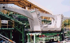
Implementation Item: U-Shaped Segments with Transverse Ribs or Struts
Country: Japan
Background: The Scanning Team was shown the Furukawa Viaduct that used the U-shaped segments with transverse ribs or struts and received a presentation on the project. Since the segments had to be transported on the public roads, the weight and size were both limited because of legal load of 30 Metric tons (33 tons) and width and height traffic restrictions. The key of the project was to select the most effective shape of segment to reduce the weight of the segment. The U-shaped core segment with horizontal rib was adopted as the final cross section of the girder. There were multiple benefits for selecting the U-shaped segment. In addition to reducing the weight, it allowed for longer segments and thus fewer segments, and the capacity of the erection equipment was reduced. The segments were erected using the span by span method with span length of 34 to 45 m (112 to 148 ft).
Other innovations incorporated in the U-shaped segments were:
- The use of high strength concrete with enhanced durability.
- The adoption of external prestressing tendons which allowed further reduction of the weight of the segments. Moreover, external tendons allow easy maintenance and easy replacement if needed in the future.
- Detail analysis with three-dimensional FEM was made for each construction phase.
- A full-scale span test was performed for each construction phase to ensure the safety of the structure since it was the first application of the unique structure and construction method.
- After erection of the segments, precast panels span longitudinally between the transverse ribs eliminating deck forming.
- It has a cast-in-place prestressed slab for enhanced durability that is replaceable if needed.
Besides providing the ability to reduce segment weight for hauling and erection, it also allows for larger segments and thus fewer segments where weight is not a constraint for hauling or span construction. Additionally, it provides an alternate superstructure type for those states that will not use conventional segmental concrete box construction because of the difficulty in removing the top slab. This superstructure design concept allows for future deck removal if needed. It is applicable to both seismic and non-seismic areas.
Strategy: The Scanning Team Implementation will consist of the following:
- Obtain sample drawings, photos of the construction and completed bridge projects for posting on the FHWA Prefabricated Bridge Website. This information will be a resource for bridge designers.
- Present the system at national conferences for AASHTO Subcommittees and Bridge conferences scheduled in 2004 and 2005. This will be a part of the information presented on the overall Prefabricated Bridge Scanning Trip.
- Disseminate the available information on the system to American Segmental Bridge Institute.
Scan Team Lead: William Nickas, Shri Bhide
Deliverables:
- Information on the U-Shaped Segments with Transverse Ribs or Struts posted at or linked from the FHWA Prefab Bridge Website.
Timeframe: The FHWA website will be updated by November 1, 2004.
Funds Required: States that contract for projects involving technology will likely be able to obtain Federal program funds, including IBRD and Highway for Life, to offset a portion of the project costs.
Deck Systems
Implementation Item: Full Depth Prefabricated Concrete Decks
Countries: Japan and France
Background: One of the three deck systems used for the ramps of the Nagoya-Minami Interchange on Route 23 is full-depth prefabricated concrete decks. Keeping the interruption to traffic on Route 23 to a minimum was of utmost importance and as such, the ramps had to be constructed very quickly. At the Route 23 Interchange, the deck panels were erected on top of steel box girders. However, they can also be used with precast, prestressed concrete girders. Although similar systems have been used in the U.S., the system used in Japan has proved to be low-maintenance and durable. One reason for the success may be the fact that all bridge decks in Japan are provided with Multiple Level Corrosion Protection System (see Implementation Item of the same name). The panels typically are full-width, pretensioned and 270 mm (10.5 in) thick. Two grout pockets per girder line per panel are provided for connection to steel girders via 3 to 6 studs in each pocket. The transverse joint between panels is made with cast-in-place concrete placed over overlapping loops of rebars with additional rebars threaded through the loops. The decks are not longitudinally post-tensioned.
Strategy: The Scanning Team Implementation will consist of the following:
- Obtain design basis, test reports, and sample drawings and specifications for both the steel and concrete girders for posting to and linking from the FHWA Prefabricated Bridge Website along with photos of construction details and completed bridges.
- Conduct literature search and research, as necessary, to validate and enhance standard connection details. Conduct static and fatigue testing of the looped bar joint details for Deck Joint Closure Detail, Inverted T Beam System, and Full Depth Prefabricated Decks. A single research effort is recommended for the Full-Depth Prefabricated Decks, Inverted T-Beam Slab Span System, and Deck Joint Closure Pour Systems. All employ overlapping loop bar reinforcement across the joint.
- Solicit States to build pilot projects.
- Coordinate with the NCHRP 12-65 project, "Full-Depth Precast Concrete Bridge Deck Panel Systems."
- Coordinate with PCI Committee developing NCHRP 12-69 project, Recommended Practice for Full-Depth Precast Deck Panels. (Joe Rose/Claude Napier).
Scan Team Lead: Shri Bhide, Ben Tang, Eric Matsumoto
Deliverables:
- Drawings, photos, and guide specifications posted or linked from FHWA website.
- Research problem statement as needed.
- Candidate projects solicited through Federal funding programs.
- Demonstration workshop.
Timeframe: FHWA website update: November 1, 2004.
Funds Required: States that contract for projects involving this type of technology will likely be able to obtain Federal program funds, including IBRD and Highway for Life, to offset a portion of the project costs.
The funding for research mentioned above is included in the funding for research on static and fatigue testing of the looped bar joint details for Deck Joint Closure Detail, Inverted T Beam System, and Full Depth Prefabricated Decks. Funding will be sought through pooled fund efforts and TRB/NCHRP.
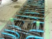
Implementation Item: Deck Joint Closure Details
Countries: Japan and France
Background: The Scanning Team saw the construction of the Anjo Viaduct, New Tomei Expressway that used the transverse adjusting joints in the top slab between the segmental segments at the piers and longitudinal connection slab between adjacent box girder segments and received presentations on the Anjo Viaduct project and the Kamikazue Viaduct. Smaller segmental box segments were used to reduce segment weight. Double loop joint was adopted for the transverse adjusting joints considering the workability at uniting the segments and errors in manufacturing the segments. Fiber reinforced expansive admixtures concrete was adopted at the transverse adjusting joints and the longitudinal connection slab between each girder. Stainless steel fibers were selected for concrete at the adjusting joints and vinylon fibers were selected at the connecting slab.
The double-loop joint was adopted at the cast-in-place connection part that is used to connect the precast box segments in which the slabs had been prestressed in the transverse direction of the bridge. The arrangement of rebars was in such a way, that a closed loop rebar (so-called side-loop rebar) that projected from the precast segments. The center-loop rebar was an annular shape, with a lap that is welded adopting enclosed welding method, considering the ease of construction. The Japanese had performed some experimental testing of full-size slab connection to prove its acceptability.
Prefabricated deck systems require that longitudinal and transverse joints be provided to make the deck continuous for live load distribution. This is accomplished by using special loop bar reinforcement details in the joints. Various joint details observed during the tour should be developed for use in the United States to facilitate the use of prefabricated full depth deck systems, longitudinal joints between adjacent boxes, and improved transverse adjusting joints, and are applicable to both seismic and non-seismic areas.
Strategy: The Scanning Team Implementation will consist of the following:
- Obtain design basis, test reports, sample drawings and specifications along with photos on this and similar systems for posting to and linking from the FHWA Prefabricated Bridge Website.
- Conduct literature search and research, as necessary, to validate and enhance standard connection details. Conduct static and fatigue testing of the looped bar joint details for Deck Joint Closure Detail, Inverted T Beam System, and Full Depth Prefabricated Decks. A single research effort is recommended for the Full-Depth Prefabricated Decks, Inverted T-Beam Slab Span System, and Deck Joint Closure Pour Systems. All employ overlapping loop bar reinforcement across the joint.
- Solicit States to build pilot projects.
- Coordinate with the NCHRP 12-65 project, "Full-Depth Precast Concrete Bridge Deck Panel Systems."
- Coordinate with PCI committee developing NCHRP 12-69 Project, Recommended Practice for Full-Depth Precast Deck Panels. (Joe Rose/ Claude Napier).
Scan Team Lead: Shri Bhide, Eric Matsumoto, Mary Lou Ralls, and Claude Napier
Deliverables:
- Drawings, photos, and guide specifications posted or linked from FHWA website.
- Research problem statement as needed.
- Candidate projects solicited through Federal funding programs.
- Demonstration workshop.
Timeframe: FHWA website update: November 1, 2004.
Funds Required: States that contract for projects involving this type of technology will likely be able to obtain Federal program funds, including IBRD and Highway for Life, to offset a portion of the project costs.
The funding for research mentioned above is included in the funding for research on static and fatigue testing of the looped bar joint details for Deck Joint Closure Detail, Inverted T Beam System, and Full Depth Prefabricated Decks. Funding will be sought through pooled fund efforts and TRB/NCHRP.
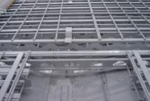
Implementation Item: Hybrid Steel-Concrete Decks
Country: Japan
Background: The Scanning Team was shown a unique hybrid steel-concrete deck system on a field trip to the New Tomei Expressway. The contractor was utilizing a prefabricated system that served as the formwork and contained the prefabricated deck reinforcement. The system was developed by Kawasaki Heavy Industries for this project and other Japanese companies have developed similar systems.
The system consisted of a bottom steel plate plus a grid of reinforcing bars and small support beams. The system spanned between girders and cantilevered beyond the fascia beam for the slab overhang. The configuration saved the contractor the need to erect forms over traffic. Shear studs were welded to the beam flange to achieve composite action.
The Scan Team noted this system was more versatile than conventional stay-in-place steel forms. It included the reinforcing and internal beam support system to form the slab overhang. The system was also light enough to be erected with small capacity cranes.
Strategy: The Scanning Team Implementation will consist of the following:
- Obtain sample drawings and specifications along with photos on this and similar systems for posting to or linking from the FHWA Prefabricated Bridge Website.
- Evaluate the details for use in the U.S. and share the results with the States.
- Coordinate with NSBA to contact potential suppliers.
- Solicit States to develop or enhance the details and build pilot projects if suppliers are available.
Scan Team Lead: Bill McEleney, Ben Tang, and Harry Capers
Deliverables:
- Drawings, photos, and guide specifications posted on or linked from FHWA Prefabricated Bridge Website.
- Pilot projects solicited through Federal programs.
Timeframe: The FHWA website update: November 1, 2004.
Funds Required: States that contract for projects involving technology will likely be able to obtain Federal program funds, including IBRD and Highway for Life, to offset a portion of the project costs.
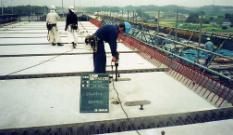
Implementation Item: Multiple Level Corrosion Protection Systems
Countries: Japan, Germany, and France
Background: In Japan, Germany, and France, concrete bridge decks are covered with a multiple level corrosion protection system to prevent the ingress of water and deicing chemicals. The systems generally involve providing adequate concrete cover to the reinforcement, a concrete sealer, waterproof membrane, and two layers of asphalt. This type of corrosion protection system may be beneficial with prefabricated systems as a means of protecting the joint regions from potential corrosion damage, thereby ensuring a longer service life.
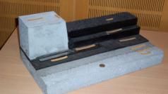
The Germans and Japanese had used a waterproof membrane with a thin asphalt overlay in the past but felt that the system did not provide the necessary protection. Additionally, the waterproof membrane was subject to damage when the deteriorated asphalt surface was milled off and replaced with a new asphalt overlay. The former asphalt overlay system needed to be replaced approximately every 10 years. Because of the poor performance of the old system, Germany developed a multiple level corrosion protection system that they have been using since the mid 1980s and feel that it will provide them a 100-year service life. The same system was adopted in Japan. The typical German deck section includes 35-40 mm asphalt wearing surface, 35-40 mm asphalt protective layer, 4.5-8.0 mm bituminous fabric seal, epoxy primer, and cast-in-place concrete deck. Typically, 30 mm is milled off when the asphalt wearing surface is replaced. The Scan Team was shown a model of cast-in-place deck. This model utilized an epoxy coating over the cast-in-place concrete deck, bituminous sheet material welded to concrete deck (2mm thick), alternative stainless steel sheet applied over the bituminous sheet, and 2 layers (8 cm) of dense graded asphalt. The Japanese have been using a 40 mm open graded asphalt mix over a 35 mm (some cases 40 mm) dense asphalt mix over a 2 to 3 mm membrane.
Strategy: The Scanning Team Implementation will consist of the following:
- Compare the German System with what is currently being used by some of the Northeast States.
- Post translated German Specifications on the FHWA Prefabricated Bridge Website. The specification will be a resource for bridge maintenance, construction, and design engineers.
- Present the system at national conferences for AASHTO Subcommittees and Bridge conferences scheduled in 2004 and 2005. This will be a part of the information presented on the overall Prefabricated Bridge Scanning Trip.
- Seek demonstration projects for 2005/2006 from the States that are currently using a waterproof membrane with a thin asphalt overlay system.
Scan Team Lead: Claude Napier
Deliverables:
- Recommendations on utilization of the system.
- Translated German Specifications and details posted on or linked from the FHWA Prefab Bridge Website.
- Note the multiple level protection system in the Federal Innovative Bridge Research and Deployment (IBRD) Fiscal Year 2005 solicitation as a corrosion protection system eligible for IBRD funding.
Timeframe: The FHWA website update: November 1, 2004.
Funds Required: States that contract for projects involving the multiple leverl corrosion protection system will likely be able to obtain Federal IBRD funds to offset a portion of the project costs.
Substructure System
Implementation Item: SPER System
Country: Japan
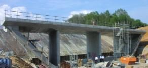
Background: The Scanning Team received a presentation on a new technology for construction of bridge piers using Sumitomo's precast form method for resisting earthquake and rapid construction called the SPER Method. The SPER Method was used on the Otomigawa Bridge on the Tanba Ayabe Road Project, Ayabe City, Kyoto Prefecture. The 4 span continuous prestressed concrete rigid frame (330m (1083 ft)) was on piers that range in height from 32.5m to 51.1m (107 ft to 168 ft).
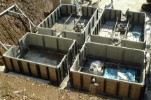
The SPER system reduces on-site project labor requirements by casting 100mm (4 in) thick precast forms with embedded lateral reinforcement at precast plant and then assemble the cross ties to the forms. The precast form assembly is transported to the project site. The construction sequence is to erect the inner precast form, set the inner precast form, erect the external precast form, set the external precast form, and then place the concrete in the forms. The Japanese have estimated that using the SPER System will shorten construction to 60-70 percent of the time required for the conventional cast-in-situ method.
The SPER system is a method of rapid construction of piers using precast concrete panels as both structural elements and formwork for cast-in-place concrete. Tall hollow piers use panels for inner and outer formwork, while shorter solid piers use panels for the outer formwork only. Testing has shown that the system provides similar seismic resistance as a conventional cast-in-place system. The system has the advantage of more rapid construction with improved constructibility and quality.
Strategy: The Scanning Team Implementation will consist of the following:
- Obtain sample drawings, photos of the construction and completed bridge projects for posting on or linking from the FHWA Prefabricated Bridge Website. This information will be a resource for bridge designers.
- Present the system at national conferences for AASHTO Subcommittees and Bridge conferences scheduled in 2004 and 2005. This will be a part of the information presented on the overall Prefabricated Bridge Scanning Trip.
- Seek demonstration projects for 2005/2006 as part of the Innovative Bridge Research and Deployment (IBRD) solicitation. Conduct workshops for DOT and FHWA engineers, contractors, and consultants.
Scan Team Lead: Barry Brecto, Eric Matsumoto, and Claude Napier
Deliverables:
- The SPER System information posted on or linked from the FHWA Prefab Bridge Website.
- The SPER System included in the Federal Innovative Bridge Research and Deployment (IBRD) Fiscal Year 2005 solicitation as a system eligible for IBRD funding.
- Demonstration project in 2005 or 2006.
Timeframe: The FHWA website update: November 1, 2004
Funds Required: States that contract for projects involving technology will likely be able to obtain Federal program funds, including IBRD and Highway for Life, to offset a portion of the project costs.