

The Implementation of Full Depth UHPC Waffle Bridge Deck Panels Final Report May 2013
3. WORK COMPLETED IN PHASE 2
The objectives of Phase 2 included the construction of the full scale demonstration bridge in Wapello County and a life cycle cost analysis (LCCA). These objectives were met by producing 14 UHPC waffle deck panels used in the demonstration bridge, creating an LCCA spreadsheet to compare the cost of conventional construction to the use of UHPC waffle deck panels over the useful life of the structure, and compiling data recorded during the first three months of the in-service performance of the demonstration bridge to determine the best estimation of the long-term performance and durability of the structure.
Waffle Panel Design
Research in the United States and Canada has shown that reinforced concrete bridge decks do not act as flexural members, but rather as low profile tied arches.(7) This research has noted the large factor of safety inherent in typically reinforced bridge decks. Factors from 8 to 10 are usually found with failures in typical decks by block shear and not flexure. Based on this study, bridge design specifications were developed in Ontario, Canada, in the early 1980s that allowed minimal reinforcing steel to be designed into bridge decks meeting required design conditions. (8) In addition, AASHTO adopted similar design specifications with the release of the Load and Resistance Factor Design (LRFD) Bridge Design Specifications in 1994.(9) In the 1990s, the Iowa DOT constructed 16 bridges on the State's primary system using the empirical deck design. The DOT's bridge office has been monitoring these bridges since their construction.
The preliminary design of the reinforcing steel for the waffle slab panels took into consideration the empirical design specifications allowed in the AASHTO LRFD Bridge Design Specifications. The empirical design allows for bridge decks that meet the required "9.7.2.4-Design Conditions" to be designed using four layers of reinforcing steel with a minimum of:
- 0.27 in2/ft in the bottom mat of reinforcing.
- 0.18 in2/ft in the top mat of reinforcing.
In the preliminary design for the test panel, no. 7 reinforcing bars were used in the bottom mat of steel at a transverse spacing of 1 foot, 9.5 inches (0.334 in2/ft) and longitudinal spacing of 2 feet, 1 inch (0.28 in2/ft). No. 6 reinforcing bars were used in the top mat at a transverse spacing of 1 foot, 9.5 inches (0.246 in2/ft) and longitudinal spacing of 2 feet, 1 inch (0.211 in2/ft).
The field cast UHPC joints were developed based on the testing done at the FHWA Turner-Fairbank Highway Research Laboratory and the details used in New York and Canada on bridge projects that had already been completed.(10)
One other factor to note in the basic design was a limit of 8 inches of overall depth. This thickness was chosen to allow the UHPC waffle deck system to be used to replace existing deteriorated bridge decks without altering the road profile.
Initial discussion for the waffle panel design also included designing for a transversely pre-tensioned concrete section that would be longitudinally post-tensioned in the field to eliminate any cracks in the panels, but one goal from the producer's view was to design the slabs with mild reinforcing. This decision would eliminate the need for prestressing capabilities in the precast plant, limiting the initial cost of the equipment and certification required to produce the slabs. Hopefully this decision will allow more producers and municipalities to adopt the UHPC waffle slab system.
Once the basic design concept was completed, FEA was performed to assist in determining the adequacy of the panel. The FEA verified the design concept, with only minor cracking predicted at the bottom of the rib section, allowing the project to move to full scale testing. At this time it was decided that the connections between the panels would also need to be tested. The connection details were primarily based on ongoing testing at FHWA.(10) The locations for connection rebar dowels were limited based on the physical dimensions of the slab, so it was decided one reinforcing bar would be located at each rib of the panel in the transverse panel-to panel-joint, and two reinforcing bars would be placed in each rib of the panel at the longitudinal panel-to-panel joint in addition to the shear key detail on the panel edge. The acceptability of the panel-to-panel connections was primarily verified through testing.
The project team reviewed the testing of the mock-up bridge section, and the final design of the waffle slab was completed in early April 2010. Shop drawings for use by production staff were complete shortly thereafter. Figures 8 and 9 show the final panel dimensions and reinforcing, respectively.
The demonstration bridge panels were designed identically to the prototype panels with respect to the shape, depth, and spacing of the ribs and voids, but changes were made to the overall size, reinforcing design, and surface texture. The demonstration bridge panels were designed to span from the centerline of the roadway to the outside of the guardrail with an overall size of feet wide by 16 feet, 2.5 inches long. A no. 7 reinforcing bar was used in both the top and bottom of each rib instead of one no. 6 and one no. 7, to eliminate possible confusion and improper installation by the production staff. A section of reinforcing was also added to the outside edge of the panel to splice into the barrier posts that resist the impact forces from a vehicle collision. The 2/102 Parana formliner texture selected from the skid resistance testing in Phase 1 was provided on the top surface of the panel to act as the final driving and wearing surface.
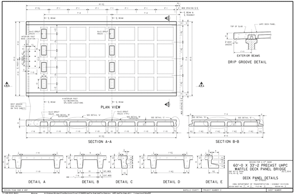
Figure 8. Diagram. Final panel dimensions
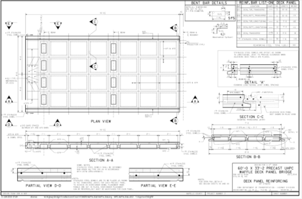
Figure 9. Diagram. Final panel reinforcing.
Testing Equipment and Plant Modifications
Special equipment is required to produce the waffle slabs and to mix, cast, cure, and test the UHPC. Most of the plant modifications required to accommodate the casting of UHPC were completed during Phase 1, including the basic formwork, UHPC mixing and placing equipment, and quality control and testing equipment. The additional modifications that were required to cast the demonstration slabs included the additional formwork used to cast the ribs and voids of the panels, and a computer controlled steam curing system. The equipment necessary to produce the UHPC waffle slabs is described in the sections below.
Formwork
No existing formwork matched the profiles of the waffle slab design or the edge conditions needed for the panel-to-panel joints. New formwork was designed and fabricated to cast the slabs. At the time of the prototype casting, the final design was unknown because testing would be required to validate the design. By researching the typical bridge designs in the Iowa highway system, it was determined that the maximum length would be 25 feet. The slab design was far enough along at the time of prototype casting to determine that the standard width would be 8 feet. The width was chosen primarily due to transportation and handling restrictions. The casting bed was fabricated by a specialized formwork manufacturer to accommodate these dimensions and was utilized to rotate the prototype waffle slabs manufactured in Phase 1. As previously mentioned, the side and void forms for Phase 1 were fabricated out of wood to serve as a temporary form in the event changes to the section needed to be made between Phase 1 and Phase 2.
The remaining formwork for the demonstration slabs was purchased after the final panel design was complete and was fabricated out of steel to allow for a high number of reuses and to conform to the tight tolerances required due to the thin UHPC sections used. The formwork consisted of a bottom form including the side forms, end forms, and the casting table acquired in Phase 1, and a top form which created ribs and voids of the panel. Figures 10 and 11 show the bottom and top form assemblies, respectively.
The formwork was selected primarily to cast the demonstration panels but was also designed to be adaptable to various rib spacings and overall panel configurations for future uses of the waffle panel system. As shown in figure 11, the pans can be removed and replaced with different sizes on the transverse beams, and the transverse beam locations can be adjusted along the length of the longitudinal beams to accommodate unlimited configurations with a limited additional investment. The bottom form is also designed to cast a deck panel up to approximately 25 feet in length to accommodate panels covering multiple lanes of traffic.
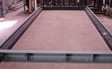
Figure 10. Photo. Casting bed and side forms
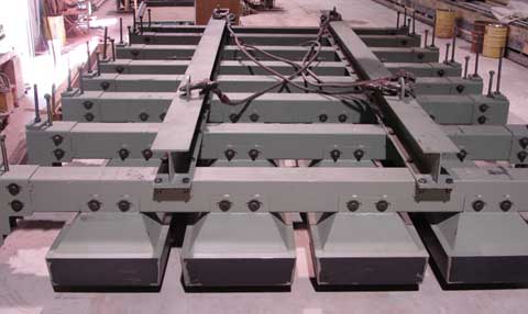
Figure 11. Photo. Void form
Casting and Initial Curing Equipment
A high shear mixer is required to adequately mix the UHPC material, and most precast plants have an existing batch plant capable of mixing UHPC without major modifications. However, typically the capacity of the mixer is reduced by approximately 50 percent due to the amount of energy required to mix the UHPC. During both the Phase 1 and Phase 2 production periods, no modifications were made to the batch plant to add steel fibers to the mixer or to automate the addition of premix bags or admixtures. All components of the mix were weighed and added manually for this project.
The manual addition of steel fibers and other components of the UHPC mixture required additional safety precautions and personal protective equipment (PPE) beyond what is required for conventional concrete production. The most difficult problem to solve was how to protect workers from the steel fibers. A very durable and puncture-resistant glove is needed to handle the fibers. The best solution found was to use a thick rubber glove (to help prevent punctures) under a heavy welding glove (to provide a thick layer of protection).
To place the UHPC in the forms, a concrete bucket was purchased in Phase 1. As mentioned previously, the bucket helped to create the alignment of the steel fibers, but it was also necessary because of the fluidity of the UHPC mix. Rubber gaskets were provided on the bucket gate to seal the opening. Previous experience with UHPC showed this was the only efficient way to transport UHPC from the mixer to the casting bed.
UHPC needs to be moist cured during the initial curing period, but steam curing was not available at the casting bed, so dry heat and moisture retention was used. To cure the panels, the exposed surfaces were covered with a shrink wrap film in Phase 1 and spray applied liquid curing compound in Phase 2 to seal in the internal moisture. Heat was applied by propane heaters for the initial curing period, and the entire form was enclosed with a tarp to contain as much heat and moisture as possible.
Quality Control Equipment
Equipment for testing fresh UHPC was purchased before the prototype panel casting and included a flow table (see figure 12), vibrating table, molds for prisms and cylinders, and scales. These items were essential for producing a high-quality product. Project personnel were trained on the equipment and related procedures before production began. A cylinder end grinder and high capacity compression testing machine are needed to accurately verify compressive strength of cured UHPC. Since this equipment was outside the budget limitations for this project, a local university was contracted to perform the testing of the hardened properties within the specifications outlined by the supplier.
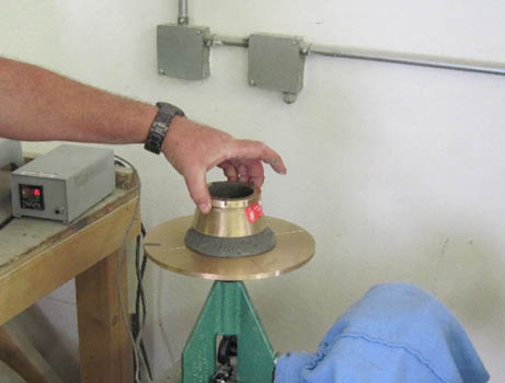
Figure 12. Photo. Flow table.
Steam Curing
To accelerate the curing process and increase the durability of the UHPC a 48-hour steam curing cycle is required. During Phase 1, the steam temperature was controlled manually by adjusting a ball valve approximately every 15 minutes. This process was inefficient and time-consuming, but it was effective in reaching the required design strength for the mock-up panels. An automated steam curing system was purchased to provide precise control and eliminate the constant monitoring and manual adjustment of the temperature for the demonstration panels. A Sure Cure system consisting of a software package, electronic equipment, and thermocouples was used to monitor the internal temperature of the curing enclosure and control the steam flow into the curing enclosure by the use of an electronically actuated valve. The software package also logs the time and temperature curve for the curing cycle to assist with quality control. See figure 13 for an example of the output. Two channels of temperature recording are shown in magenta and orange, and one channel of ambient temperature is shown in black.
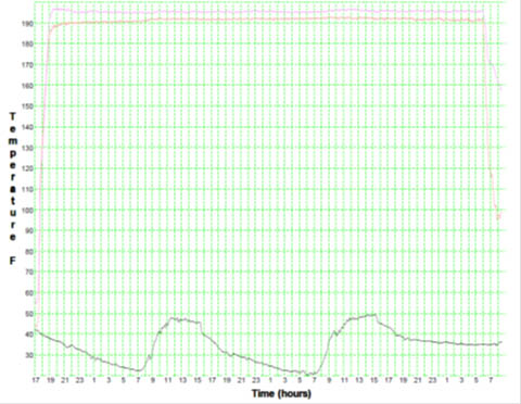
Figure 13. Graph. Time vs. temperature
Other Plant Modifications
Additional equipment and plant modifications were considered in the original proposal, including a fiber distribution system for mixing UHPC, the installation of an automated bed heat system to cure the fresh UHPC, construction and installation of a permanent steam curing chamber, and the purchase of special equipment to handle the slabs from the edges. Knowledge gained during the course of the project proved that these items were not required and did not prove to be cost-effective for this project alone. Commercial fabrication of UHPC may warrant the purchase of these items based on the volume of product required.
Impact on the Precaster
In general, the modifications required to produce the UHPC waffle deck panels were very limited, and for small quantities of UHPC production, no modifications to the plant would be required beyond formwork. If more than one or two castings are required, it is recommended to invest in the products purchased for this project, including a bucket, testing equipment, and a curing system to improve the efficiency and safety of the operation. The process and timing related to producing UHPC compared to conventional concrete is the biggest change to the production environment. Once a process is implemented and a new mindset of the crew producing the panels is reached, the process runs smoothly.
Demonstration Project Panel Fabrication
The demonstration project panels were produced with the same basic process as the prototype panels. Figure 14 shows the form setup for the first demonstration panel casting. Uncoated reinforcing was used on the demonstration panels because only very minor cracking on the bottom surface of the panel was observed during the laboratory testing of the prototype panels. However, the dowels entering the field cast joints were made of stainless steel to provide an additional factor of safety against the possibility of corrosion at the interface between the plant and field cast UHPC. Unlike the prototype panels, no monitoring instruments were cast into the panels.
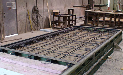
Figure 14. Photo. Initial form setup
Figure 15 shows the placing of the UHPC into the form. The UHPC was placed with the same specially designed bucket that was used for the prototype panels. Along with being able to transport the extremely fluid material, the bucket helps to align the steel fibers in the UHPC in the longest direction of the panel. The bucket was moved along the length of the form and kept behind the leading edge of the flow to eliminate any discontinuity in the fiber orientation.
The form was filled to a predetermined level based on the total volume of UHPC required for a panel, and then the voids were set as an assembly (see figures 16 and 17). Each of the prototype panels required approximately 2 cubic yards of UHPC. By placing the voids as an assembly, the panels can be cast quickly while keeping the size and spacing of the ribs very accurate. As with the prototype panels, the UHPC is displaced by the voids as they are lowered into position to create the final shape of the piece.
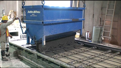
Figure 15. Photo. Placing UHPC
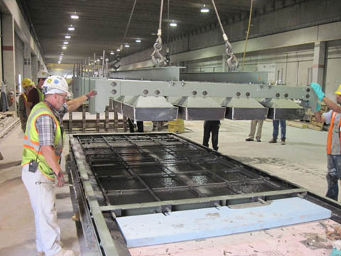
Figure 16. Photo. UHPC placed to correct level
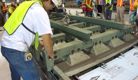
Figure 17. Photo. Placing the voids
As mentioned previously, by forming the panels upside down and using a displacement casting method, the voids can be removed after the initial set of the UHPC, which allows the UHPC to shrink unrestrained. Damage from shrinkage will occur between initial set and stripping if the appropriate precautions are not taken. The use of steel forms increased the need to remove the voids promptly because the form was extremely rigid compared to the prototype panel form made of wood and foam. Using the displacement technique also helps to randomly orient the fibers in the rib sections. Figure 18 shows the panel after the formwork is removed.
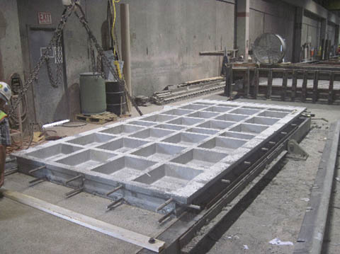
Figure 18. Photo. Formwork removed (panel upside down)
After the required 14,000 psi release strength was verified, the panels were lifted into the vertical position by the casting bed (see figure 19), rotated 180 degrees about a vertical axis, and lowered back to the horizontal position in the proper orientation by the casting bed similar to the prototype panels (see figure 20). The panels were then moved from the casting area to the curing area.
Checking the release strength was one of the challenges faced by the plant when dealing with UHPC. A 3-inch by 6-inch cylinder with 14,000 psi compressive strength could be tested at the precast plant using existing compression machine, but the ends of the cylinders could not be prepared to the flatness tolerance outlined in the specifications. The cylinders were ground flat by hand, not by a machine, so the compressive strength measured was most likely a conservative value due to stress concentrations on the cylinder ends caused by unevenness. The alternative to this conservative method was to deliver individual cylinders to the local university and have them tested every time release strength needed to be verified, but this was not feasible due to time constraints in the production schedule.
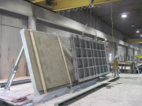
Figure 19. Photo. Lifting the panel to vertical
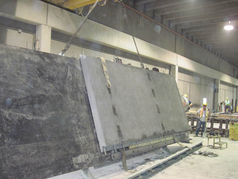
Figure 20. Photo. Panel rotated back to horizontal (panel right side up)
The panels were cured for 48 hours at 195 °F, as required by the supplier for maximum strength and durability. Prior to steam curing, the panels measured approximately 15,000 psi compressive strength. A series of test cylinders were broken after the steam curing was completed to verify that the panels had been cured correctly, and the compressive strength of the UHPC at that time was an average of 33,700 psi, substantially exceeding the required design strength of 24,000 psi. After curing was complete, the panels were stored until they were needed at the demonstration bridge job site.
Demonstration Project Construction
The demonstration bridge in Wapello County is 33 feet, 2 inches wide by 60 feet long, consisting of 14 UHPC panels supported on five Iowa "B" beam precast/prestressed concrete girders spaced at 7 feet, 4 inches, with overhangs measuring 1 foot, 11 inches. The panels are jointed with UHPC at the crown longitudinally, the transverse panel-to-panel joints, and the shear pockets over the girders. The demonstration bridge plan and cross section are shown in figures 21 and 22, respectively.
The design of the demonstration bridge and deck panels was completed in early April 2010; however, due to an extraordinary amount of rainfall and flood damage around the bridge site, the construction schedule was delayed by approximately 1 year. The letting for the general contractor occurred in May 2011, and construction began in August 2011. A full set of plans for the demonstration bridge, including the panels and connections, is included in the appendix.
The general contractor proceeded with construction quickly. The existing bridge was removed the week of August 15, 2011, and new substructure and abutments were completed by September 5, 2011. The precast beams and UHPC panels were set in place starting the week of September 12, 2011, followed by the approach slabs and other associated road work. The total time to install the bridge was less than 4 months.

Figure 21. Diagram. Plan of the demonstration bridge
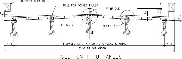
Figure 22. Diagram. Cross section of the demonstration bridge
Panel Installation
The panels were delivered by truck to the demonstration bridge site, where they were offloaded and stacked until they were needed. The panels were set over a period of 2 days, and simple slings were used for rigging. The sequence of installation was from south to north on the east side and from north to south on the west side, due to the layout of the reinforcing dowels. Steel shims were placed under the panels to align the top surface of the panels and provide a smooth driving surface. Two layers of half-inch compressible foam weather stripping were placed along the top surface of the beams to seal the gap between the beams and panels to contain the field cast UHPC placed in the longitudinal panel joint and shear pockets. Figure 23 shows the deck panels being set, and figure 24 shows a close-up of the panels in place.
The contractor had no major problems installing the panels, and the east side of the bridge was completed in only a few hours since each panel’s transverse joint dowel bars were designed to set on top of the previous panel’s dowel bars. The only minor issue was the installation of the second panel on the west side of the bridge. The panel was difficult to install because of the overlapping reinforcing dowels in both the transverse and longitudinal joints, but after a few adjustments to the rigging, the contractor was able to slide the panel into position. The same rigging technique was used for the remaining panels on the west side of the bridge without any issues.
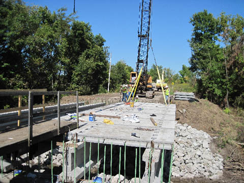
Figure 23. Photo. Setting the deck panels
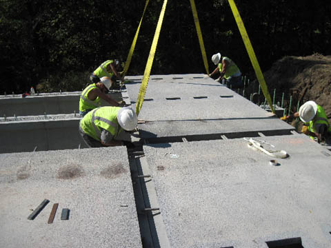
Figure 24. Photo. Close view of the deck panels.
Joint Fill
The field cast UHPC joints were poured on September 27 and 28, 2011. The transverse panel-to-panel joints on the east side were cast on September 27, and the transverse panel-to-panel joints on the west side, along with the longitudinal crown joint, were cast on September 28. The UHPC was mixed on-site with two portable mixers. Approximately 222 feet of joint were cast on September 27, and 282 feet were cast on September 28. The UHPC was placed using wheelbarrows and a funnel system. Figures 25 and 26 illustrate the construction sequence of filling the joints and shear pockets with UHPC.
The transverse panel-to-panel joints were set tight together, but they were also sealed with a bead of silicone caulking to ensure no UHPC leaked out of the joint during casting. The longitudinal joint and the shear pockets were sealed with the weather stripping applied to the beams during construction. Weather stripping was also applied to the top side of the panels at all field cast locations to act as a form extension and ensure there were no areas of the joint that were underfilled.
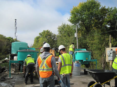
Figure 25. Photo. Portable mixers for batching joint fill UHPC
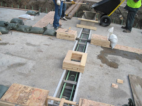
Figure 26. Photo. Transverse joint casting
A layer of sealed plywood was placed over the weather stripping at the joints and shear pockets after they were filled with UHPC to prevent moisture loss during the curing period. Small risers were placed on each joint and filled with UHPC to provide positive fluid pressure on the joints to force air out of the mix and keep the joint completely filled. Sandbags were placed on top of the plywood to keep the UHPC from leaking out of the joints and onto the deck due to the pressure from the riser and the bridge slope.
According to the supplier, casting went very well. If it had not rained the day before casting delaying form preparation, the entire joint fill process could have been finished within an 8-hour work day. The contractor was also very easy to work with and was open to suggestions relating to the joint fill process. The only negative of the joint fill was one low spot in the UHPC on the first day of casting. The imperfection was noticed prior to casting the second day, and two layers of weather stripping were used instead of the single layer used on the first day.
Figure 27 is a photograph of the completed demonstration bridge.
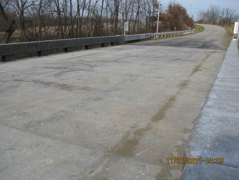
Figure 27. Photo. Completed demonstration bridge
In-Situ Testing and Evaluation
Field testing was used to evaluate the performance of the UHPC waffle deck panels under true service conditions. The demonstration bridge was opened to traffic in November 2011 and field tested in February 2012. The field testing included monitoring of live load deflections and deformations at discrete, critical locations on the bridge superstructure as it was subjected to static and dynamic truck loads. A 3D FEA of the bridge was used to help interpret the results of live load testing, estimate strains due to dead load, and examine live load distribution.
Two UHPC waffle deck panels along the length of the bridge were selected for instrumentation. One of these panels was located near the mid-span, and the other was located adjacent to the south abutment, as illustrated in figure 28. Surface-mounted strain gauges were used on each panel and their adjacent UHPC joints to quantify deformations and identify the likelihood of cracking under service loads. The locations of these strain gauges were selected to coincide with critical locations on the panels and deck joints where stress and strain would likely be extreme.
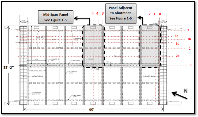
Figure 28. Diagram. Locations of monitored panels
In addition to the strain gauges on the deck panels, 13 surface-mounted strain gauges and five string potentiometers were attached to the girders to characterize the global bridge behavior, measure mid-span deflections, and quantify lateral live load distribution factors. Using two additional string potentiometers, deflections were also measured at the mid-spans of the deck panel located near the center of the bridge. Top and bottom girder strains were also monitored for three of the girders at mid-span and at a section 2 feet from the south abutment.
Live load was applied by driving a heavily loaded dump truck across the bridge along predetermined paths. The total weight of truck was 60,200 lb, with a front axle weight of 18,150 lb and two rear axles weighing roughly 21,000 lb each. For static tests, the truck was driven across the bridge at a speed of less than 5 miles per hour. Each load path was traversed twice to ensure repeatability of the measured bridge response. For dynamic tests, the truck speed was increased to 30 miles per hour to examine dynamic amplification effects.
The results of the testing were promising. The maximum strains and deflections experienced by the demonstration bridge during the field tests were well within expected performance parameters. No strains recorded on the top of the deck indicated a likelihood of cracking or opening of joint interfaces that might adversely affect durability. The only locations where strains approached the anticipated cracking threshold of the UHPC waffle deck were on the underside of the panel adjacent to the abutment. These cracks were small in width, and the strains recorded during the test were less than those recorded on the laboratory test panels at service load levels.
In general, the UHPC waffle deck panels performed very well and appear to be more than capable of holding up to the rigors of use on a public highway.
Additional details of the Phase 2 field testing are expected to be published in the 2013 proceedings of the PCI Convention and National Bridge Conference (E.H. Gheitanbaf, J.M. Rouse, and S. Sritharan, authors).