U.S. Department of Transportation
Federal Highway Administration
1200 New Jersey Avenue, SE
Washington, DC 20590
202-366-4000
Federal Highway Administration Research and Technology
Coordinating, Developing, and Delivering Highway Transportation Innovations
| REPORT |
| This report is an archived publication and may contain dated technical, contact, and link information |
|
| Publication Number: FHWA-HRT-11-062 Date: November 2011 |
Publication Number: FHWA-HRT-11-062 Date: November 2011 |
The CCTs provided important data on the relative corrosion of the experimental and control steels in the laboratory test. The outcomes of the CCTs are represented in thickness loss per corrosion cycle. To predict thickness loss in a severe high-chloride bridge environment, three of the experimental steels were exposed to actual bridge service at the Moore Drive Bridge over I-394 S in Rochester, NY. ASTM A1010 and ASTM A588 have been studied previously at the Moore Drive Bridge.(11)
The mechanical property results described previously showed that only ASTM A1010 steel is a candidate for bridge construction. However, the CCTs results showed a strong positive effect of Cr, a strong negative effect of Si, and a strong positive effect of Al. The steels selected for exposure on the Moore Drive Bridge were 9Cr, 7Cr2Si, and 7Cr2Al. By testing these three steels, it was hoped that insights could be made on the relative atmospheric corrosion resistance of Cr, Si, and Al alloy additions to high-Cr steel in an adverse outdoor environment.
To accommodate the test racks on the Moore Drive Bridge, standard 4- x 6- x 0.100-inch (106- x 152- x 2.54-mm) coupons were cut in half to create 4- x 3- x 0.100-inch (106- x 76- x 2.54-mm) coupons. The Moore Drive Bridge has racks in three separate locations relative to the roadway. Racks 1 and 2 are near the abutment and over the roadway, respectively. Studies have shown that the corrosion behavior on racks 1 and 2 are similar. Rack 3 over the Erie Canal and more than 100 ft (30 m) away from the roadway provides a significantly different microclimate for atmospheric corrosion testing. Due to space constraints on racks 1 and 2, the coupons for the present study were distributed between these two racks. Triplicate specimens were placed on the bridge on November 18, 2008.
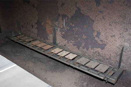
Prior to removal from the Moore Drive Bridge on October 13, 2009, the coupons were photographed on their racks (see figure 36). Following storage in the laboratory for 3 days, the coupons were weighed to determine mass gain. XRF spectrometry was used to determine elemental composition, including chloride, of the surface rust at several locations on each surface of each coupon. XRF had also been used to analyze elemental composition of the rust on webs and flanges of Moore Drive Bridge near the exposure racks.
Figure 36. Photo. Corrosion coupons on Moore Drive Bridge on rack 1 just prior to removal after 1-year exposure.
The rust was stripped from two of the triplicate coupons for each steel using a combination of mechanical (hammer), bead blast, and chemical stripping processes. Rust was removed from the UA of the six coupons by hammer. The first rust removed was not tightly adhered and was labeled semi-adherent. Rust that remained on the steel was very adherent, and small amounts were able to be gently scraped off using a steel blade. Care was taken not to scrape the steel surface. The semi-adherent and the very adherent rusts were then ground to fine powders and analyzed by XRD to determine the iron oxide compositions and by XRF to determine the elemental chloride concentrations. The chloride concentration remaining on the steel surface was also measured following the initial mechanical strip and also after the final chemical strip. The same procedure was repeated for the DA of each coupon.
Following rust stripping, thickness loss of the steel was calculated for each coupon. Table 17 presents the corrosion loss of each of the three developmental steels. Also included for reference are the corrosion losses of ASTM A588, HPS 50W, and ASTM A1010 steel coupons exposed on Moore Drive Bridge racks 1 and 2 from 2001–2009, 2007–2008, and 2005–2009, respectively. The measured losses for ASTM A1010 are about one-fourth the losses of weathering steels, but this is not as much a difference as the approximately one-tenth loss expected from laboratory corrosion tests.
Table 17. Thickness loss of experimental steels exposed and historical data for control steels exposed on Moore Drive Bridge.
Steel |
Rack |
Coupon 1 (mpy) |
Coupon 2 (mpy) |
Average (mpy) |
9Cr |
2 |
1.079 |
1.058 |
1.07 |
7Cr2Al |
2 |
1.111 |
1.109 |
1.11 |
7Cr2Si |
1 |
1.161 |
1.228 |
1.20 |
ASTM A588 |
2.43 |
|||
ASTM HPS 50W |
2.03 |
|||
ASTM A1010 |
0.58 |
|||
1 mil = 25.4 m | ||||
Based on the CCT results, it was expected that 9Cr and 7Cr2Al would have the same corrosion rate. This behavior was supported by the Moore Drive exposure rates of 1.07 and 1.11 mpy (27.2 and 28.2 µm per year), respectively. Steel 7Cr2Si was expected to experience a significantly higher corrosion rate than the other two steels. While its rate was higher, the difference was slight at 1.20 mpy (30.5 µm per year).
Year-to-year variability in corrosion rates on the Moore Drive Bridge make it impossible to precisely compare different materials exposed during different time periods. However, the thickness loss of the experimental steels exposed at the Moore Drive Bridge is approximately one-half the measured 2–2.4 mpy (51–61 µm per year) experienced by ASTM A588 weathering steel and its metallurgical equivalent ASTM HPS 50W. The lowest corrosion rate measured on the Moore Drive Bridge is ASTM A1010, which is about one-half the loss of the experimental steels and one-fourth the loss of conventional weathering steels.
The morphology of the rust on each of the three developmental steels was very similar. Each coupon was covered with a uniform medium brown semi-adherent rust layer on the UA. The surface rust was flakey. The DA of each coupon was darker brown and less uniform in color across the surface. The loose surface rust was more granular than flakey. A small amount of semi-adherent, flakey, and granular rust was easily removed from their corresponding surfaces. Under the surface rust was a very adherent fine powder rust that was carefully scraped off by chisel for analysis. Overall, much more semi-adherent rust was present on the coupons than the very adherent rust.
Table 18 shows the composition of the semi-adherent and very adherent rust samples removed from the UA of each developmental steel. In the coupon code, "sa" indicates the semi-adherent outer rust on the steel, and "va" indicates the very adherent rust on the steel under the "sa" layer.
Table 18. Composition of the rusts on the upward-facing surface of the three experimental steels exposed on Moore Drive Bridge (percent).
Steel Type |
Temp. (ºF) |
Coupon Code |
Akaganeite |
Goethite |
Lepidocrocite |
9Cr |
1,350 |
68AC1UAsa |
66 |
31 |
3 |
68AC1UAva |
74 |
18 |
8 |
||
7Cr2Si |
1,200 |
73AC1UAsa |
71 |
19 |
10 |
73AC1UAva |
63 |
30 |
7 |
||
7Cr2Al |
1,200 |
75AC1UAsa |
73 |
22 |
5 |
75AC1UAva |
70 |
26 |
4 |
||
°C = (°F-32)/1.8 | |||||
The rust composition on the UA was similar for all three experimental steels. Akaganeite was the most abundant oxide and comprised about 70 percent of the rust. Goethite made up about 24 percent of the rust, and lepidocrocite made up about 6 percent. Notably absent was maghemite, which was present in large volumes on the CCT coupons. This difference emphasizes that the CCT protocol based on the SAE J2334 test is fundamentally different that actual field environments for bridges exposed to deicing salts.
There were no clear rust compositional differences between the sa and va rust samples. Table 19 lists the percentage of each rust constituent for the three coupons sa and va rusts removed from the three types of steel. The rust compositions are similar to those measured on the ASTM A588 coupons exposed on the Moore Drive Bridge on racks 2 and 3. The dominant presence of akaganeite (and suppression of lepidocrocite) is due to the large chloride concentrations deposited on the bridge at racks 1 and 2, road deicing activities, and heavy traffic volumes passing beneath the bridge.
Chloride levels were measured on the coupons and in the rust at several stages of the exposure project. XRF data were recorded on one of the bare steel coupons of each steel type prior to mounting on Moore Drive Bridge. Chlorides present at this time are expected to be a result of the past exposure and stripping of the coupons. Once removed from the bridge after 329 days, the UA and DA of the corroded coupons were measured for chlorides prior to rust stripping. This was repeated after strip 1 (mechanical) to measure the chloride concentrations under the rust and at the steel surface in the presence of some va rust. XRF data were also recorded on the sa and va powdered rust samples removed from the coupons for XRD analysis. Finally, XRF recordings were made on the clean UA of the coupons following the final chemical strip.
At the time of coupon removal from the bridge, XRF measurements were made on the bridge girders in the vicinity of racks 2 and 3. Two readings were made on the web above rack 2D. The first was made on the outer surface of the loose web rust, which was then rubbed off by hand to permit the second reading to be taken on the more adherent rust beneath. One final XRF reading was taken at the far end of the bridge on the web close to the east abutment above rack 3D. This location is far removed from direct chloride deposition from interstate I-390. At this location, the rust is va and thin and has a composition close to that of a fully protective patina on weathering steel. Table 19 summarizes the chloride levels measured on coupons and the bridge.
Table 19. Chloride concentrations measured in the rust formed on Moore Drive Bridge (percent).
Steel Type |
Temp. |
Coupon Code |
Bare |
Rust Surface (After Exposure) |
After Strip 1 |
Bare |
Rust Powder |
|
9Cr |
1,350 |
68AA1U |
0 |
6.9 |
6.8 |
0.65 |
sa |
11.5 |
va |
6.0 |
|||||||
68AA1D |
0.18 |
7.8 |
7.8 |
nd |
nd |
nd |
||
7Cr2Si |
1,200 |
73AA1U |
0 |
9.3 |
5.3 |
0.54 |
sa |
11.0 |
va |
6.2 |
|||||||
73AA1D |
0 |
9.9 |
6.3 |
nd |
nd |
nd |
||
7Cr2Al |
1,200 |
75AA1U |
0 |
8.4 |
6.7 |
0.52 |
sa |
11.1 |
va |
5.7 |
|||||||
75AA1D |
0.11 |
7.5 |
7.1 |
nd |
nd |
nd |
||
Average |
nd |
0 |
8.3 |
6.7 |
0.57 |
sa |
11.2 |
|
va |
6.0 |
|||||||
°C = (°F-32)/1.8 nd = Not determined. | ||||||||
Prior to exposure on the bridge, four of the six coupon surfaces that were analyzed contained no detectable chloride. The exceptions were two DAs that contained about 0.15 percent chloride. This value was much smaller that the chloride levels deposited at the bridge site and was not expected to have affected the mass loss measurements. When removed from the bridge, the chloride concentrations at the rust surfaces prior to stripping were very high and averaged about 8.3 percent across the coupons, including UA and DA. The chloride concentrations did not appear to vary between the UA and DA or between steel type. The data in table 19 also show that the chloride concentrations on both surfaces of each coupon were similar and averaged about 6.7 percent, which was lower than on the original rust surface. In agreement with this trend are the chloride concentrations in the sa and va rust samples removed from the coupons at strip 1.
XRF analysis of the rust powders provides the most accurate chloride concentrations in the bulk of the rust formed during the steel exposure. The data show that there was a higher chloride concentration of about 11.2 percent in the sa rust (less dense/more porous outer rust) than in the va (inner) rust, which contained about 6 percent. The chloride levels at the steel surface, although still very high, were less than the chloride accumulation in the bulk rust. This difference was likely due to the low porosity and flakey nature of the outer rust, which could allow more chloride to permeate and collect in it while blockading it from reaching the steel by the more adherent rust.
It is interesting to note that the chloride concentrations in the rust that attached to the girders of Moore Drive Bridge were much lower than in the coupon rust. A rack 2, the concentrations of chloride in the web rust was about 0.87 percent, which was significantly smaller than in the rust of the steel coupons. It is possible that the difference was due to the salt water draining from the vertical web surface, whereas the same was not true for the horizontal coupon surfaces. The chloride concentration on the web at rack 3, located 200 ft (61 m) from I-390, was about 0.21 percent.
The three experimental Cr steels exposed on Moore Drive Bridge were about twice as corrosion resistant than ASTM A588 steel from which the bridge was constructed. The three experimental steels did not exhibit much variation in corrosion rate among themselves and did not form a protective rust patina to permit the corrosion rates to decrease after prolonged exposure times. The lower corrosion rates of the Cr steels were therefore controlled primarily by their higher alloy concentrations under aggressive salt exposures. The lowest corrosion rate measured on the Moore Drive Bridge continues to be ASTM A1010, which is about one-half the loss of the experimental steels and one-fourth the loss of conventional weathering steels.