U.S. Department of Transportation
Federal Highway Administration
1200 New Jersey Avenue, SE
Washington, DC 20590
202-366-4000
Federal Highway Administration Research and Technology
Coordinating, Developing, and Delivering Highway Transportation Innovations
| REPORT |
| This report is an archived publication and may contain dated technical, contact, and link information |
|
| Publication Number: FHWA-HRT-15-049 Date: April 2015 |
Publication Number: FHWA-HRT-15-049 Date: April 2015 |
![[top] Photo. Side view of a van-pulled falling weight deflectometer. [top] Photo. Side view of a van-pulled falling weight deflectometer.](images/appendix_c_001.jpg) |
|
![[bottom left] Photo. Front view of an inertial profiler [bottom left] Photo. Front view of an inertial profiler](images/appendix_c_003.jpg) |
![[bottom right] Photo. View of a roadside electronics box, alongside a highway, that collects traffic monitoring data. [bottom right] Photo. View of a roadside electronics box, alongside a highway, that collects traffic monitoring data.](images/appendix_c_002.jpg) |
The LTPP program has used state-of-the-art equipment and technology to collect high-quality data. In many cases, the devices and software used to collect, process, and perform quality control/quality assurance (QC/QA) on the data have been created by the SHRP-LTPP and FHWA-LTPP contractors because the technology either did not exist or did not meet the performance needs of the program.
The following sections describe some of the equipment used by the program over the years. In addition, this appendix also covers the software used for processing and performing QC checks of the data collected. Please note that the information contained in the following pages is not a complete list of the equipment or the software used by the program, but this additional information is being provided because it may be of value. More complete information about each type of data collection equipment and software used to process the data can be found in other documents published by the LTPP program, many of which are referenced throughout this report, particularly in chapter 6 and chapter 7.
The automated weather station (AWS) equipment installed at the SPS-1 (structural factors for flexible pavements), -2 (structural factors for rigid pavements), and -8 (environmental factors in the absence of heavy loads) projects included:
The LTPP regions with SPS projects in freeze zones were provided with heated tipping buckets (figure C.1) that required 110-volt service to power the heater.
Software routines for the Campbell Scientific, Inc. (CSI) CR10 Datalogger were developed as a DOS-based program that was downloaded to the CR10 Dataloggers.1 This program complemented the field data collection and calibration activities by controlling the field data collection functions and providing the file format for storage of the instrumentation data. In 2004, the DOS-based program was updated to work with CSI’s PC208W program, which was based on Microsoft Windows®.
In 1997, the installation of modems at each AWS location to allow for remote data download became a requirement.2 Modems were added to sites that could be provided with landline telecommunications at a reasonable cost (figure C.2), and cellular packages were added to sites that were not phone-line accessible.
Prior to the implementation of the SHRP program, very little falling weight deflectometer (FWD) data had been collected. Since deflection data were to be a key data element in the LTPP program, FWD units were purchased and evaluated for deflection data collection.
The first four FWD units for the LTPP program were procured from Dynatest® in 1988. The FWDs were towed by a 1988 GMC diesel van (figure C.3) and were equipped as follows:
Five-year maintenance programs were included with the procurement, requiring the FWDs to be delivered annually to the manufacturer for service.
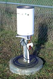 FIGURE C.1. Heated tipping bucket rain gauge. |
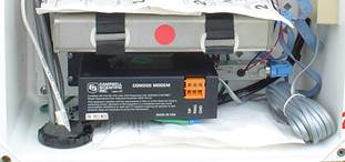 FIGURE C.2. Modem attached to Datalogger for transmitting data via landline to the respective LTPP regional support contractor’s office computer. |
 FIGURE C.3. One of the four original FWD van and trailer units. |
Since the purchase of the first set of FWD units in 1988, the LTPP program has made a concerted effort to maintain the equipment. Driven by budget restrictions, in some years, the program found it more economical to refurbish the units instead of replacing them altogether. The manufacturer refurbished the FWD units in the early years of the LTPP program, but in later years, the LTPP regional support contractors were given the option to refurbish the units using the expertise of their staff or by sending the units to the manufacturer. All units, whether new or refurbished, are required to pass the reference calibration at one of the regional calibration centers (see chapter 6 for more detail) prior to collecting deflection data at the LTPP test sites. Table C.1 lists the FWD equipment used in the LTPP program from 1988 to 2014.
The Dynatest DOS v20 FWD field program had the option of smoothing the FWD load and deflection peaks, as typically a 2-point peak occurs at the time of initial impact and full loading of the buffers. For the LTPP program, no smoothing was applied as the desire was to provide data in an unadjusted state. The flat buffers that initially came with the FWD units were problematic in that they provided too harsh a contact, which resulted in a very uneven peak. To alleviate this, Dynatest conducted a rotating knife cut on the buffers to provide a tapered buffer that would cushion more on impact due to the reduced contact area. The first modified buffers had too much of a taper such that their warming would cause the weight assembly to bounce back into the catch. Two additional versions of the buffers were developed (100 mm and 110 mm) that had a mild curvature to the bottom. These buffers were used for the remainder of the program.
The LTPP program developed procedures for cold weather testing as part of the Seasonal Monitoring Program (see chapter 7). To keep the FWD units operating during the winter months, the LTPP regional support contractors added block heaters to keep the hydraulic fluid warm so the hydraulics would continue to operate. However, the AC current from the heaters created a spike in the peaks, which was noticed at the time of reference calibration. Procedures were then developed to ensure that the heaters were turned off at the test site and that testing would be terminated if temperatures dropped below 15 °C (5 °F).
Pavement temperatures were initially measured using the Williamson infrared temperature sensors provided with the FWDs. They were problematic in that they were intermittent in their operation. These infrared sensors were replaced with a Raytec infrared surface temperature probe. Regional calibration of the infrared sensors also determined an issue with the consistency of temperature output. After each calibration, the temperature coefficients changed, although slightly. It was decided that this change resulted in unreasonable differences. The procedures were modified in 2005 to allow the regions to perform calibration checks, while temperature calibration changes would only be performed by the manufacturer.3
| Year | Equipment |
|---|---|
| 1988 | Purchased 4 FWDs, equipped with
Laptop computer—8000 series processor1988 GMC diesel vans and dual-axle trailers with enclosed bodies |
| 1995 | Refurbished 4 LTPP regional FWDs and purchased 4 new FWDs:1
9000 series processorPurchased 8 Ford diesel vans |
| 2000 | Upgraded FWDs:
9 deflection sensorsReplaced FWD vans |
| 2002 | Refurbished FWDs |
| 2005 | Upgraded FWD software to FWDWin hanged file format to Microsoft® Access® |
| 2006 | Disposed of 1 FWD in each region (transferred to other FHWA operations and the National Center for Asphalt Technology in Auburn, AL) |
| 2013–2014 | Refurbished FWDs Purchased 4 diesel Chevrolet 2013 Express 3500 passenger vans Upgraded FWD software to new CP-15 system |
| (1) The additional FWDs were needed to meet the demands of the Seasonal Monitoring Program and the addition of many SPS projects. | |
Automated Temperature Datalogger
In 2008, the LTPP program developed the automated temperature data logger (ATDL) and the software used to determine surface and thermal gradient temperature measurements at FWD test locations (figure C.4 and figure C.5). The ATDL process was developed to replace the manual method, which used a handheld temperature reader and probe to collect temperature data at the time of FWD data collection. The automated process allows for collecting temperature data at the same time each FWD data point is collected. The previous practice for collecting this information was at 30-minute and 1-hour intervals. Although the setup was proven to be successful and some 16 units were assembled, this method was not implemented by the LTPP regional support contractors due to funding reductions that resulted in the suspension of FWD data collection at most LTPP test sites (with the exception of some SPS projects).
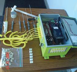 FIGURE C.4. Automated Temperature Datalogger with temperature probes attached. |
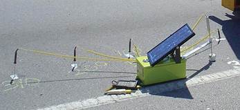 FIGURE C.5. Automated Temperature Datalogger setup in the field. The Datalogger is powered by a 12-volt SLA battery. The solar panel charges the battery to sustain 12 volts during data collection. |
A 60-millisecond (ms) window was used to capture the loading and response history data. However, there were requests from researchers for 100-ms histories. The LTPP program investigated this request at the time of the Dyna25 implementation and, based on the added time required to store the histories, decided to continue with the 60-ms histories. The Dynatest program produced output files in the *.FWD format with the history data embedded in the binary file. So, the LTPP program developed a field QC software tool–FWDScan–to ensure that the FWD data met the minimum requirements (number of drops and repeatability) before sending the data to the office.4,5
The LTPP program began to migrate the FWD data from U.S. customary units to the International System of Units (SI) in 1999. The FWD setup was modified to output in SI units.
In 1989, SHRP purchased three DNC 690 Profilometers from K. J. Law to collect longitudinal profile data. The profilers used a Champion motor home chassis with Ford underpinning with dual rear wheels. These Profilometers used:
A fourth Profilometer, mounted in a Ford E350 van chassis, was obtained from FHWA and delivered to the LTPP North Central Regional Coordination Office Contractor. This van had the same profiling system but was mounted in a smaller unit. The data collection and computing were handled by a PDP 1184 with disk drive and tape backup. Profile elevations were sampled at 1-inch (25-mm) intervals, averaged over 12 inches (305 mm), and reported at 6-inch (152-mm) intervals.
As the technology for profiling equipment improved, the LTPP program upgraded its units. New units were subsequently purchased in 1996 and then again in 2002. Starting in 1996 with the purchase of the K. J. Law T6600 Profilometers, SI units have been used for collecting and storing the profile data. In 2013, the LTPP program took delivery of four new, state-of-the-art inertial profiling units manufactured by Ames Engineering that meet LTPP’s stringent acceptance criteria. The competitively procured profilers replaced LTPP profilers that were in service since 2002 and collectively logged more than 1.2 million miles (1.9 million km). Table C.2 lists the profiling equipment used in the LTPP program since delivery of the first profilers in 1989.
Sample data were collected and stored at 1-inch (25-mm) intervals with the conversion to the K. J. Law T6600 Profilometer. A 12-inch (305-mm) running average was being applied to the 1-inch (25-mm) data output at 6-inch (152-mm) intervals. In discussion with K. J. Law, no filtering was to be applied to the 1-inch (25-mm) data. It was later discovered that a running average was applied on the 1-inch (25-mm) data. Since data were additionally being filtered by the LTPP regional support contractors, the profiles were being double-filtered. Researchers using these data should be aware that this was never rectified, and this double filtering is still present in the data in the LTPP database.
Capabilities
The latest LTPP profilers (purchased in 2013) were specified and manufactured so the results from the testing regimen closely match legacy LTPP data collection parameters. The new units not only collect longitudinal profile data, but have added capabilities. Pavement macrotexture measurements are a new data collection element, and all of the data, including ambient and surface temperature, are now referenced with Global Positioning System coordinates. The cockpit of the vehicle has been designed to minimize driver distractions and provide ease of access to all controls and testing switches. As compared to the old LTPP profilers that used 2002-era computer technology, the new system’s hardware requirements are minimized, resulting in a very low computer rack footprint. System software has been designed through a collaborative manufacturer/LTPP program process to be user-friendly and intuitive.
| Year | Equipment |
|---|---|
| 1989 | Purchased 3 K. J. Law DNC 690 Profilometers
DEC PDP 1184 computer processor with disk drive and backup3 mounted in Champion motor home chassis with Ford underpinning, dual rear wheels 1 mounted in a Ford E350 van (DNC 690 Profilometer obtained from FHWA) Video cameras added after delivery in some regions |
| 1996 | Purchased 4 K. J. Law T6600 Profilometers
IBM-compatible computer, integrated MS-DOS®/Windows® systemMounted in Ford E350 extended vans Change from U.S. customary units to SI units |
| 2002 | Purchased 4 International Cybernetics Corporation MDR 4086L3 Profilers
3 laser/accelerometer sensorsMounted in Ford E350 vans |
| 2003 | Updated calibration oscillation integrated into processor |
| 2013 | Purchased 4 Ames Engineering, Inc. Profilers
3 laser/accelerometer sensorsMounted in Ford E150 vans |
Acceptance Testing
The new LTPP profilers were procured and accepted for service using a very strict procedure. This procedure could be leveraged by other agencies that are procuring inertial profilers to check the ability of the equipment to collect consistent, accurate profile and macrotexture data. The acceptance procedure, conducted in February 2013, consisted of the following checks:
To conduct the acceptance testing, several reference test sections were established near College Station, Texas. These sections consisted of two asphalt concrete, two Portland cement concrete, and one chip seal surface. The sections were selected to obtain a range of roughness and MPD values. The results were analyzed and it was found that all four profilers met the stated requirements. Following acceptance testing and analysis of the data, a week-long training exercise held in April 2013 for the LTPP regional support contractors paved the way for the LTPP program to incorporate the new devices into production mode for data collection.
The instrumentation and data collection equipment used as part of the seasonal monitoring program (SMP) included:
Thermistor and Resistivity Probes
Thermocouple and resistivity probes were assembled in Albany, New York, at the State highway agency. The agency had experience with the thermistor probes, and information on the resistivity probe was provided by CRREL. Thermistor probes were considered but decided against based on problems CRREL had using this technology in Vermont and New Hampshire. At this time, thermistor probes manufactured by MRC were in their infancy and little was known regarding their performance. A Troxler moisture probe was loaned from the vendor who was working with New York on the use of this device. The LTPP program purchased a precision Hewlett-Packard multi-meter for the thermocouple and resistivity probe data collection and an Omega channel selector to multiplex through the various thermocouples. An oscillator (developed from plans provided by CRREL) was assembled for resistivity probe data collection. Some other methods were considered for frost/thaw determination, but time limitation eliminated these from the initial installation.
A function generator and multiplexer developed by FHWA’s Turner-Fairbank Highway Research Center replaced the initial manual 2-pt and 4-pt resistivity multiplexers. The instrumentation for measuring air and pavement temperature and precipitation was connected to a CR10 Datalogger and mounted in a cabinet at the site location.
The MRC surface thermistor probes that were contained in the 330-mm stainless steel probe had a high failure rate. It was suspected this was due to the flexing of this probe under traffic loading (since they were placed in the surface layer in the wheelpath). Replacement probes, which contained three “piglet” style mini probes, were installed to replace the failed probes for Phase II SMP sites (figure C.6). Each probe was placed independently within the surface layer at a defined depth.6
Time Domain Reflectometer
TDR probes were used to obtain the moisture content in unbound base and subgrade materials. The TDR technique is based on the measurement of the travel time of an electromagnetic wave induced into a waveguide, in this application, a moisture probe. The apparent length is the length between the beginning and end points on the waveform, which correspond to the beginning and end of the metal tube portion of the moisture probe. This apparent length of the probe can be used to calculate the dielectric constant of the material surrounding the probe. The dielectric constant is an input to the calculation of moisture content.
The LTPP program evaluated TDR probes of various configurations (2-prong, 3-prong, short and long probes, straight or curved probes, with or without baluns, etc.) using Sonotubes™ with various soils and moisture levels to select the type of probe and using the Topp, Roth, and Paterson analytic procedures.
Problems were encountered with TDR activation when using the CR10X Dataloggers. Support was sought from CSI, but this issue was never resolved. It was never determined if the issue was a problem with the CR10X Datalogger or if the program was too complicated for the CR10X processor. CSI had indicated that they had problems with the crystal in some of the CR10X Dataloggers, but the ones they delivered to FHWA for the SMP Phase II program were not part of this group. The solution was to regularly check the Datalogger outputs and reload the program if the TDR system went idle. This resulted in some of the early data sets being incomplete.
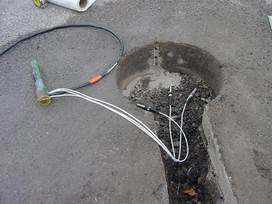 FIGURE C.6. “Piglet” style mini-probes installed to replace failed thermistor probes in Phase II of the Seasonal Monitoring Program. |
The continuous moisture and frost/thaw data collection in SMP Phase II was accomplished by integrating a Tektronics cable tester and an ERB20 resistivity multiplexer (manufactured by ABF, Inc.) with the existing onsite instrumentation at select sites and in the mobile units. The ERB20 multiplexer, which replaced the CRREL multiplexer, recorded the input voltage, which allowed for the mathematical interpretation of the automated resistivity data.
In addition to the Tektronics cable tester and ABF multiplexer, the Dataloggers were upgraded to the CSI CR10X-2M along with CSI multiplexers, cabinet, and remote telecommunication capabilities. The software, OnsPlus, incorporated an “Agency Machine” to initiate the TDR system based on the level and intensity of rainfall, and initiated the resistivity system based on below-freezing gradient temperatures from the MRC temperature probe. To extend the period between site visits, CSI SM-192 data storage modules were added. The SM-192 storage modules had 5-volt lithium batteries that provided reserve power to the memory chip to help prevent data loss.7