U.S. Department of Transportation
Federal Highway Administration
1200 New Jersey Avenue, SE
Washington, DC 20590
202-366-4000
Federal Highway Administration Research and Technology
Coordinating, Developing, and Delivering Highway Transportation Innovations
 |
||
 | report |  |
| This report is an archived publication and may contain dated technical, contact, and link information | ||
| Federal Highway Administration > Publications > Research > Infrastructure > Structures > Geosynthetic Reinforced Soil Integrated Bridge System Interim Implementation Guide |
Publication Number: FHWA-HRT-11-026
Date: January 2011 |
Geosynthetic Reinforced Soil Integrated Bridge System Interim Implementation GuideCHAPTER 3. MATERIALSBuilding GRS is as easy as 1–2–3: (1) a row of blocks (the facing elements), (2) a layer of compacted granular fill to the height of the facing blocks, and (3) a layer of geosynthetic reinforcement. The materials used for each step of the process need not be proprietary and are readily available. Recommendations are made to optimize the design based on numerous case histories and field experiments. There are also several miscellaneous materials needed for the details of GRS–IBS.
3.2 FACING ELEMENTS The facing element is not a structural member of GRS–IBS. Its purpose is to provide a form for compaction, serve as a façade, and protect the granular fill from outside weathering. Since the facing is not a structural element of a GRS mass, it is up to the user to define the type of facing used. It may be made of various materials, including concrete, timber, natural rock, metal, automobile tires, shotcrete, and gabion baskets. While some of the facing elements shown would not be appropriate for use in GRS–IBS bridges, figure 2 shows various facing elements that have been used in the construction of GRS walls.
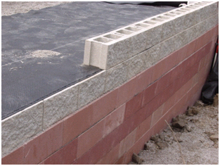
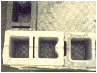
The most commonly used facing element for GRS walls and abutments is the split face concrete masonry unit (CMU) with nominal dimensions of 8 inches by 8 inches by 16 inches and actual dimensions of 75/8 inches by 75/8 inches by 155/8 inches (see figure 3 and figure 4). It is important to use the actual dimensions in designing and detailing GRS–IBS. CMU blocks are lightweight, easy to place, and ensure compaction at every 8–inch lift before placement of the next geosynthetic layer. As seen in figure 3, the reinforcement extends directly beneath each layer of CMU blocks as a frictional connection.
The CMU should have a minimum compressive strength of 4,000 psi and a water absorption limit of 5 percent. In colder climates, a freeze–thaw test (ASTM C1262–10) should be conducted to assess the durability of the CMU and ensure it follows the standard specification (ASTM C1372). One method to ensure the overall quality of the CMU is to review the QA/QC process of a particular producer. There are several types of CMU that are commonly used in GRS–IBS construction: solid face, hollow core, and corner block. All of these blocks come in the standard dimensions previously described. In addition to the 7 5⁄8–inch height, there are a 3 5⁄8–inch solid CMU blocks that can be used as spacers to form the beam seat (see chapter 7). CMU blocks have been used for GRS construction because they are readily available and inexpensive. They are also compatible with the frictional connection to the recommended reinforcement. Since the facing element is not structural in a GRS wall or abutment, any facing element can be used. With other facing elements, however, special design considerations may apply, and such considerations are beyond the scope of this guide. Backfill selection for GRS–IBS is important because it is a major structural component for the abutment. The backfill must be properly compacted to a minimum of 95 percent of maximum dry density according to AASHTO T–99. Other procedures to determine the degree of compaction can also be used (e.g., modulus–based test methods), as discussed in chapter 7. In GRS–IBS construction, other areas to consider for backfill selections are the RSF and the integrated approach. Locally sourced aggregates, as long as they meet the material qualifications, are the most economical choice for GRS construction. Most State specifications for aggregate, which are usually met by local quarries and aggregate suppliers, will satisfy the material requirements. Recommendations are provided in this section for GRS abutment, RSF, and approach–way backfills. It should be noted that some backfill materials are easier to work with than others. Certain backfills are more suitable for compacting behind a given facing element than others. These factors need to be considered when selecting the backfill for a given project. It has been observed that some fine–grained sands and open–graded coarse aggregates with a maximum grain size greater than 2 inches are difficult to compact directly behind the face of a frictionally connected split face CMU block. The selection of a compatible fill and facing element is therefore necessary for the following purposes:
Because a GRS abutment is designed to support load, the backfill is considered a structural component. Abutment backfill should consist of crushed, hard, durable particles or fragments of stone or gravel. These materials should be free from organic matter or deleterious material such as shale or other soft particles that have poor durability. The backfill should follow the size and quality requirements for crushed aggregate material normally used locally in the construction and maintenance of highways by Federal or State agencies. Abutment backfill typically consists of either well–graded or open–graded aggregates (example Lower quality granular or natural fill materials can be used if the amount of fines is limited to less than 12 percent for drainage. However, a performance test must be conducted (see appendix B) to quantify the deformation and composite behavior of the mass. The engineer should be cautious when using fills of a lower quality than specified, as the allowable load may be significantly reduced. Safety factors for reinforcement strength and ultimate capacity will also deviate from what is specified in design (see chapter 4). It is therefore recommended to follow the abutment backfill specifications outlined in this chapter. In addition to the gradation requirement, the backfill selection is dependent on the following factors:
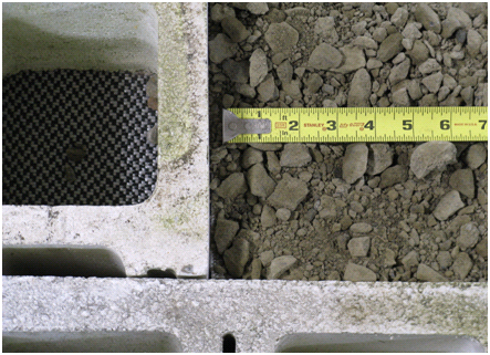
3.3.1.1 Well–Graded Backfill Most State transportation department subbase aggregates have a specification for well–graded backfill. A maximum grain size of 2 inches is recommended for efficient compaction behind the abutment wall facing. An example of this type of aggregate is shown in table 1 and in figure 5. The exact gradation is not required. As long as the maximum aggregate size is not exceeded, the amount of fines passing the No. 200 sieve is not greater than 12 percent, and the friction angle is at least 38 degrees, the backfill material will be adequate for GRS–IBS. Table 1. GRS abutment well–graded backfill (VDOT 21–A).
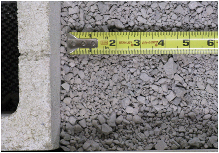
3.3.1.2 Open–Graded Backfill Recommended open–graded backfill material consists of clean, crushed angular (not rounded) stone. The minimum maximum grain size to efficiently achieve compaction behind the abutment wall face is 0.5 inches. An example of a typical open–graded abutment backfill is shown in table 2 and in figure 6 . The amount of fines passing the No. 200 sieve should be as close to 0 percent as possible and no more than 5 percent. Table 2. GRS abutment open–graded backfill (AASHTO No. 89).
3.3.2 RSF Backfill The backfill for the RSF should be well–graded so a dense packing can occur during compaction. The recommended backfill is the same as that used in abutment construction (see table 1). 3.3.2.1 Riprap Protection Riprap protection should be sized appropriately for the class of stone specified. The stone used should be hard, durable, angular, free of organic and spoil material, and resistant to weathering and water action. It should be free of clay or soft shale seams that can slake when exposed to water. Hydraulic Engineering Circular 23 (HEC–23) should be used to adequately size riprap or other scour countermeasures.(5) 3.3.3 Integrated Approach Backfill The GRS located directly behind the beam end is necessary to provide a smooth, integrated transition from the approach way to the bridge deck. This area of GRS–IBS is called the approach–way transition. The fill material used for this transition should be a well–graded gravel similar to that used for the RSF backfill (see table 1). 3.4 GEOSYNTHETICSince GRS is generic, there are many types of geosynthetic materials of various strengths available for abutment construction. At the time of this report, all in–service GRS–IBSs have used a biaxial, woven polypropylene (PP) geotextile in the abutment. This geotextile was used for several reasons, including cost, ease of placement, and compatibility with the friction connection that is used between the block facing and the GRS mass. While any geosynthetic meeting the requirements outlined in this section can be used in the abutment, a geotextile must be used for the RSF and the integrated approach to encapsulate the material. An ultimate strength of at least 4,800 lb/ft is used for GRS load–bearing applications. In some cases, it might be appropriate to specify stronger reinforcement strength depending on the design requirements. Chapter 4 provides design guidance on the required reinforcement strength for a particular application, which is a function of the lateral stress, reinforcement spacing, and backfill properties. The reinforcement strength at 2 percent strain is also an important consideration in the performance of GRS–IBS (see chapter 4). Limiting the required reinforcement strength to less than the reinforcement strength at 2 percent strain will ensure long–term performance and serviceability. In some situations, the permittivity and apparent opening size of a geosynthetic need to be considered to ensure adequate long–term drainage, particularly when the abutment may be submerged at any point. Since the use of a free–draining backfill is recommended in this situation, a rapid release of water from the reinforced soil fill can occur. Nevertheless, the impact of water on wall design needs to be considered, particularly in situations where rapid drawdown can occur as the result of receding floodwaters. It is also important to ensure that the geosynthetic material is capable within its specific environment. Geosynthetics can be either uniaxial or biaxial, meaning the reinforcement either has more strength in one direction or it has equal strength in both directions along its length. The term machine direction (or warp direction) refers to the strength along the length of the roll, and the term cross–machine direction (or fill or weft direction) refers to the strength along the width of the roll (see figure 7 ). If a uniaxial reinforcement is used, having greater strength in the cross–machine direction allows for easy placement, as the geosynthetic can be rolled out parallel to the wall. When using geosynthetics that are uniaxial in the machine direction, the placement must be perpendicular to the wall, adding to construction time. It is recommended, however, that biaxial reinforcement be used to eliminate construction placement errors and ensure approximately equal strength in both directions.
It is important to properly select the geosynthetic for the specific site conditions. The following should be specified for geosynthetic reinforcement:
3. Conformance criteria.
3.5 MISCELLANEOUS MATERIALSThe three main materials involved in GRS construction are the facing element, the backfill, and the geosynthetic reinforcement. Other miscellaneous materials are also necessary during construction, including the following:
|
||||||||||||||||||||||||||||||||||||||||||||||||||||||||||