
This section describes the various concerns associated with drainage and utilities, such as lighting and sign supports, around noise barriers.
Because of their locations and relationships to the highway, barriers often interfere with normal drainage patterns related to surface runoff paths both parallel and perpendicular to the highway. This requires special treatments within and adjacent to the barrier. Options for addressing drainage issues in the vicinity of noise barriers are discussed below.
Where acoustical requirements permit it and geometrics allow it, a barrier overlap section can be constructed. While such sections are normally built to provide access gaps in longer sections of noise barriers, they can be well suited as a means of carrying water past and through a barrier (see Figures 185 and 186). Additional discussion related to barrier overlap is included in Section 9.4.1. Details related to acoustical requirements of such overlaps are discussed in Section 3.5.5.1
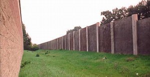
Figure 185. Drainage: use of barrier overlap
photo #901
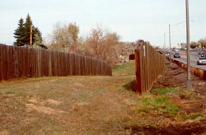
Figure 186. Drainage: use of barrier overlap
photo #382
A variety of sizes and shapes of openings in barriers have been employed to carry water, which would otherwise pond on one side of the barrier, through the barrier (see Figures 187 and 188. The essential consideration in this type of design is to assure that the size and location of such openings do not result in any significant degradation of the barrier's acoustical performance. The effect of a continuous gap of up to 20 cm (7.8 in) at the base of a noise barrier is usually within 1 dB(A).ref.32 An important consideration is to assure that proper protection in the form of grates or bars is provided to restrict entry by small animals (cats, small dogs, etc).
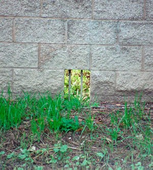
Figure 187. Drainage: water through a barrier
photo #1414
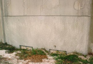
Figure 188. Drainage: water through a barrier
photo #1132
Several techniques have been used to carry water underneath a barrier. The most common is via the use of a swale system running parallel to the barrier (see Figure 189 and 190], or feeding water to catch basins (inlets) through which pipes running underneath the barrier are connected (see Figures 191 and 192). Depending upon the grades in the vicinity of the barrier, such swales may be required on either the highway side or the adjacent property side of the noise barrier. These pipes may carry water to a discharge point onto the ground surface or to the closed pipe or open culvert drainage system of the highway.
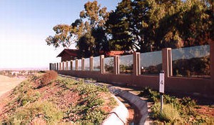
Figure 189. Drainage: water along a barrier
photo #984
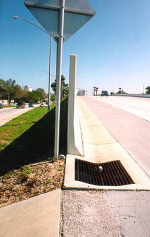
Figure 190. Drainage: water along a barrier
photo #1065
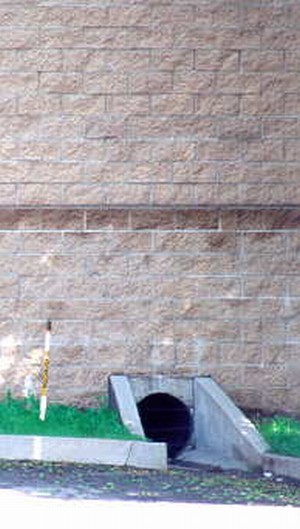
Figure 191. Drainage: water underneath a barrier
photo #1798
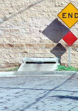
Figure 192. Drainage: water underneath a barrier
photo #1799
Another method of carrying water underneath a barrier is by providing a porous stone trench beneath the base of the barrier through which water can seep in a manner similar to that of a subdrain. An adaptation of this treatment involves erecting the barrier with its panel bottoms raised several inches above the adjacent ground elevation and then mounding porous stone on both sides of the barrier to close the gap while also allowing water to pass through (see Figure 193). These porous stone systems require maintenance to assure they do not seal up over time with sediments. These types of treatments must be compatible with the type of noise barrier erected. A barrier erected with a continuous footing will preclude the use of either of the porous stone techniques.
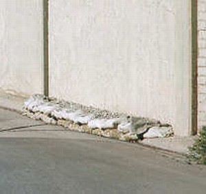
Figure 193.Drainage: water underneath a barrier
photo #2071
In some instances, it is necessary to construct noise barriers in areas subject to flooding conditions in which flood water would actually flow across the highway. Since a noise barrier would naturally restrict such flow and exacerbate the water flooding condition, the bottom panels of a precast concrete panel system can be hinged so that the pressure of any built-up water would swing the panels outward, allowing the release of flood waters. Following the passage of the flood water, the panels would swing back into a vertical position (see Figure 194)
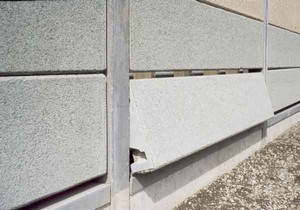
Figure 194. Drainage: water through a swing panel
photo #6168
Where noise barriers are required to be constructed in the vicinity of such features, a variety of techniques have been employed (see Figure 195). In some cases, concrete cast-in-place noise barriers have been poured right up to concrete utility poles. In other cases, walls have been offset or have had inserts constructed to accommodate utility elements such as transformers and poles. While major sign supports are accommodated in a similar manner, supports for smaller signs (such as yield signs) as well as other features such as call boxes have been mounted directly to the facade of the noise barrier walls (see Figure 196 and 197). When mounting such elements on noise barriers, care needs to be taken to assure that adequate horizontal and vertical clearances are provided.
Figure 195. Lighting incorporated into a barrier system
photo #1180
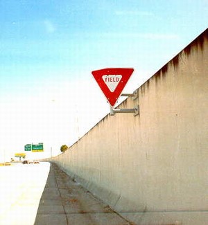
Figure 196. Other elements mounted on a barrier
photo #1074
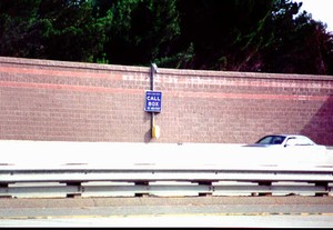
Figure 197. Other elements mounted on a barrier
photo #1432
The presence of underground utilities can have a major bearing on the type of noise barrier designed and the location of such a barrier. Significant utilities in the path of a barrier can preclude the use of certain types of deep footings (e.g., pile type footings) and require use of either a shallow spread footing or a barrier design which requires no footing (see Figure 198). An undulating noise wall configuration (in plan view) may be advantageous in "jogging around" underground utilities (see Figure 199).
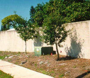
Figure 198. Effects of underground utilities on barier design
photo #1089
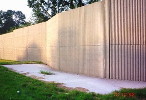
Figure 199. Effects of underground utilities on barier design
photo #2228
The presence of overhead utilities may restrict the size of components used in construction of a barrier (see Figure 200 and 201). If vertical clearances are limited, smaller precast elements (such as stacked panels) and smaller lifting equipment may be required. In certain instances, the use of a crane or any heavy construction equipment may be precluded altogether by vertical clearance restrictions. In such cases, precast panel designs may be excluded as an option or may require special posts which enable the panels to be placed from the side rather than set in from above (see Figure 202). Barrier type may also be limited to a block wall, a cast in place wall, or some other system which can be constructed without the use of lifting or heavy construction equipment. Consideration of both the post and panel elements must be made.
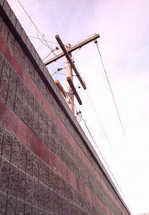
Figure 200. Effects of overhead utilities on barrier design
photo #835
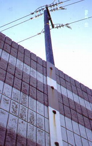
Figure 201. Effects of overhead utilities on barrier design
photo #5288
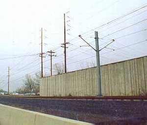
Figure 202. Effects of overhead utilities on barrier design
photo #869
|
Drainage and Utility considerations for all noise barriers. |
||||
|---|---|---|---|---|
| Item# | Main Topic | Sub-Topic | Consideration | See Also Section |
| 7-1 | Drainage | Barrier Overlap | Ensure the acoustical requirements of such overlaps are met | 3.5.5.1 7.1.1 |
| Accommodating Water Through a Barrier | Ensure that the size and location of openings do not result in degradation of acoustical performance, and also ensure protection in the form of grates or bars is provided to restrict entry by small animals. | 7.1.2 | ||
| Accommodating Water Under a Barrier | If a porous stone systems is used, maintenance is required to ensure it does not seal up over time with sediments. | 7.1.3 | ||
| Flood Plain Areas | Include possible design additions where the bottom panels of a precast concrete panel system can be hinged so that the pressure of any built-up water would swing the panels outward, allowing the release of flood waters. | 7.1.4 | ||
| 7-2 | Lighting, Sign Supports, Utility Poles, Etc. | . | When mounting traffic or safety-related elements on or adjacent to noise barriers, care needs to be taken to ensure that adequate horizontal and vertical clearances are provided. | 7.2 |
| 7-3 | Underground Utilities | . | Utilities in the path of a barrier can preclude the use of certain types of deep footings and require use of either a shallow spread footing or a barrier design which requires no footing. An undulating noise wall configuration may be used to "jog around" underground utilities. | 7.3 |
| 7-4 | Overhead Utilities | . | If vertical clearances are limited, stacked panels and smaller lifting equipment may be required - or the barrier type may be limited to a block wall or a cast-in-place wall. | 7.4 |

