U.S. Department of Transportation
Federal Highway Administration
1200 New Jersey Avenue, SE
Washington, DC 20590
202-366-4000
Federal Highway Administration Research and Technology
Coordinating, Developing, and Delivering Highway Transportation Innovations
| REPORT |
| This report is an archived publication and may contain dated technical, contact, and link information |
| Publication Number: FHWA-HRT-14-039 Date: May 2014 |
Publication Number: FHWA-HRT-14-039 Date: May 2014 |
The 0.6-inch, 270-ksi low-relaxation grade PT strand was used in this study. Great care was taken not to contaminate the surface of the strands during the handling and storage. More than 50 center (i.e., king) wires were extracted from 5-ft-long PT strands by untwisting and removing the outer six wires. These king wires were used for the electrochemical testing of task 2.1, which called for electrochemical testing of instantaneous corrosion rate and corrosion potential of king wires exposed to different aqueous test solutions having 10 chloride concentrations and 2 pH values. The sodium chloride weight in a test solution was equivalent to the chloride concentration in a grout mix expressed in terms of weight percent of cement that was calculated based on the cement content of 33.3 lb per grout bag (50 lb) and 12.5 lb of distilled water for each bag. The following calculations exemplify a chloride concentration equivalent to 1.0 percent chloride by weight of cement:
Table 2. Sodium chloride contents for task 2.1 test solutions.
| Chloride Concentration by Weight of Cement (percent) | Weight of Sodium Chloride in 0.26-gal Water (oz) |
|---|---|
| 0.00 | 0.000 |
| 0.04 | 0.063 |
| 0.08 | 0.123 |
| 0.20 | 0.308 |
| 0.40 | 0.616 |
| 0.60 | 0.924 |
| 0.80 | 1.232 |
| 1.00 | 1.540 |
| 2.00 | 3.077 |
| 3.00 | 7.693 |
Table 3 lists the chemical compositions for making solutions with a pH of 9.0 and 13.6, respectively, in the 0.26-gal test solutions.(14) These solutions were prepared to simulate carbonated grout and concrete (pH 9.0) and high alkaline environment like uncarbonated grout and concrete (pH 13.6). These represent typical pH values observed in the field.
Table 3. Chemical compositions for task 2.1 test solutions.
| Solution with pH 9.0 | Solution with pH 13.6 | |||
|---|---|---|---|---|
| Sodium Carbonate | Sodium Bicarbonate | Calcium Hydroxide | Sodium Hydroxide | Potassium Hydroxide |
| 0.147 oz | 0.875 oz | 0.070 oz | 0.291 oz | 0.816 oz |
A total of 64 50-lb grout bags were acquired from a local distributor of the same manufacturer that produced the grout containing the elevated chloride. It is claimed to be a non-shrink, non-bleed, high flow, sand-free, cementitious grout. Upon receiving them, three bags were randomly selected for trial mixes to cast 10 4-by-8-inch cylinders for determining background chloride and confirming that the calculated weights of sodium chloride were correct to produce the target chloride concentrations. For this, seven chloride concentration mixes and three chloride-free mixes were cast. Table 4 provides final sodium chloride weights needed to produce the target chloride concentrations in the full batches based on the following:
Table 4. Sodium chloride weights for tasks 2.2 and 2.3 specimen grout mixes.
| Chloride Concentration by Weight of Cement (percent) | Weight of Chloride Ions Required for One 50-lb Grout Bag (lb) | Weight of Chloride Ions Required for Six 50-lb Grout Bags (lb) | Weight of Sodium Chloride Required for Six-Bag Grout Mix (lb)* | Weight of Water Required for Six-Bag Grout Mix (lb)** | Total Weight of Six-Bag Grout Mix (lb)*** |
|---|---|---|---|---|---|
| 0.00 | 0.00 | 0.00 | 0.00 | 75.00 | 375.00 |
| 0.08 | 0.03 | 0.16 | 0.26 | 75.00 | 375.30 |
| 0.20 | 0.07 | 0.40 | 0.66 | 75.00 | 375.70 |
| 0.40 | 0.13 | 0.80 | 1.32 | 75.00 | 376.30 |
| 0.60 | 0.20 | 1.20 | 1.98 | 75.00 | 377.00 |
| 0.80 | 0.27 | 1.60 | 2.64 | 75.00 | 377.60 |
| 1.00 | 0.33 | 2.00 | 3.30 | 75.00 | 378.30 |
| 2.00 | 0.67 | 4.00 | 6.59 | 75.00 | 381.60 |
| *60.7 weight percent of sodium chloride is chloride ions. |
| **12.5 lb of water per bag. |
| ***6 bags × 50 lb per bag + 75 lb of water + sodium chloride. |
Proportional amounts of sodium chloride were admixed for the trial mixes as shown in table 4. After they were cured for 10 days in ambient condition, acid-soluble and water-soluble chloride analyses were made with the grout powder samples obtained by drilling the hardened grout cylinders. The former was done by American Association of State Highway and Transportation Officials (AASHTO) T260 and the latter by ASTM C1218.(15,16) The entire acid-soluble chloride test results reported in this report was done according to AASHTO T260 standards. The chloride test results are presented in chapter 4 of this report.
A perfect agreement existed between admixed chloride concentrations and extracted chloride concentrations in the trial mixes. The grout mixing and pumping was performed in an industrial grade grout mixing system.
To accelerate corrosion of fabricated PT specimens, one large and one small walk-in environmental chamber were employed by converting two commercial grade walk-in freezers. The smaller chamber had an interior footprint of 6 ft, 4 inches × 12 ft, 4 inches, and the larger one had an interior footprint of 11 ft, 4 inches × 12 ft, 4 inches. The interior height of both chambers was 6 ft, 11.5 inches. In addition to a standard freezer evaporator and refrigeration unit, each chamber had infrared heat lamps, a humidifier, a dehumidifier, and a digital thermostat to control the temperature between -10 and 120 °F and RH between 30 and 100 percent. Figure 3 through figure 6 show exterior and interior views of the chambers, respectively. A data collection terminal cabinet and fabricated specimens are also shown in figure 4 through figure 6.

Figure 3. Photo. Environmental chambers.

Figure 4. Photo. Inside the small environmental chamber.

Figure 5 . Photo. Inside the large environmental chamber.

Figure 6. Photo. Data collection terminal cabinet.
An accelerated corrosion testing protocol was developed to produce discernible test results within 6 months. Because corrosion reaction is greatly influenced by temperature and moisture level (RH), cyclic temperature and humidity variations simulating outdoor environmental condition to which the PT bridges are exposed in field were maintained inside the environmental chambers.
Fabricated specimens were exposed for a full cycle of 8 weeks in the following sequence:
Temperature and RH in the chambers were recorded continuously using universal serial bus-based monitoring sensors. Ambient temperature and temperature/RH in the chambers were also manually measured at the time of performance data collection. At the same time, specimen interior temperature was measured using thermocouples placed in the two specimens. The experimental data were collected twice per cycle: the first one in the middle (end of the first week) and the second one at the end of the exposure cycle (end of the second week). After the second data collection was completed, the exposure cycle was switched to the next scheduled one. Data collection from the single-strand control specimens was made bi-weekly at end of the second week as they did not show noticeable changes in the corrosion activity due to their exposure to only room temperature. Condition of strands exposed in the void were also occasionally inspected and photographed. More discussion will be made in the Corrosion Performance Tests and Data Collection section in this chapter.
Weekly corrosion performance of the accelerated corrosion testing specimens was monitored with two types of electrochemical measurements. These non-destructive data are commonly used to characterize corrosion behavior of metallic specimens embedded in cementitious materials non-destructively subjected to various levels of chloride contamination and environmental loading.
The first experimental dataset collected in this study was corrosion potential. It indicates the thermodynamic tendency of the specimens to determine whether corrosion initiation is possible or not. ASTM C876 provides three corrosion potential criteria with respect to copper/copper sulfate reference electrode (CSE) to determine corrosion tendency of steel embedded in concrete as follows:(17)
The second experimental dataset in this study reviewed the instantaneous corrosion rate of single-strand specimens. It provided kinetic information about the intensity of corrosion once corrosion started. This information is vital to predict remaining life of a system or a structure by estimating how fast corrosion takes place. As the word “instantaneous” implies, it determines the rate of corrosion at the moment of measurement, and it can change anytime depending on external and internal conditions including temperature and moisture content. It is calculated from experimentally determined polarization resistance (Rp) with the assumption that corrosion occurs uniformly over the entire surface area. Corrosion rate is usually expressed by mils per year. In reality, active-passive metals like PT strands exposed to highly alkaline environment are damaged at finite fixed spots. This form of localized corrosion includes pitting corrosion and crevice corrosion. Although the underlying assumption of uniform corrosion is incorrect, the present study uses the collected nominal corrosion rate data with caution because there are no other alternatives to provide the corrosion rate information.
The next section briefly discusses electrochemistry of localized corrosion caused by a breakdown of passive film on reinforcing steel and strand exposed to uncarbonated concrete, mortar, or grout. The passive film is formed during anodic polarization, as shown in figure 7.
The anodic polarization process of a metal involves moving electrical potential of the metal (working electrode of an electrochemical test cell) toward more a positive direction from its reversible potential, as illustrated by the green arrows in figure 7. One way of achieving anodic polarization is through a potentiodynamic polarization technique using advanced electrochemical instruments. They enable researchers to conduct specific anodic polarization experiments with great precision and predetermined polarization limits, scan rates, etc. During the initial upward anodic polarization, corrosion current density increases (i.e., corrosion rate of the metal increases). This region is defined as the active zone as indicated in figure 7. When continuous anodic polarization process makes current density exceed a critical value (icritical), current density drops substantially to a passive current density level (ipassive). At this current density level, passive film starts to build up on the metal surface in the presence of oxygen, and, consequently, corrosion rate of the metal decreases. With further anodic polarization in the positive potential direction, quality of the passive film is increasingly enhanced, and corrosion rate remains low. This region is called the passive zone, as indicated in figure 7. When the anodic potential reaches the pitting potential (Epit) and beyond, pits start to form on the metal surface and grow as function of anodic potential. Above a certain potential, oxygen gas also evolves by water dissociation. This region is labeled the transpassive zone, as indicated in figure 7. A cyclic potentiodynamic anodic polarization technique can be also employed to investigate pitting corrosion behavior of a particular metal. Basically, it is a reversed anodic polarization process once the anodic polarization curve reaches a pre-set limit in the transpassive zone. This step is shown as the blue line and blue arrows in figure 7. The area surrounded by the hysteresis loop indicates the degree of susceptibility to pitting corrosion. A larger area is more susceptible to pitting corrosion. The potential where the reversed anodic polarization curve and the upward anodic polarization curve intersect is called the protection potential (Eprot) or repassivation potential. No pitting occurs below Eprot, whereas pits can nucleate and grow above Epit. Between Eprot and Epit, no pits can form, but existing pits can grow.

Figure 7. Graph. Major characteristics of active-passive metals presented in a potential-log current density (E-log i) diagram.
Figure 8 illustrates the effect of chloride ions on passivity of steel. As the chloride concentration increases, the passive zone shrinks, and both ipassive and icritical increase due to weakened or compromised passive film. Consequently, a much higher corrosion rate should be expected at any corrosion potential for steel exposed to chloride contaminated concrete, mortar, and grout.

Figure 8. Graph. Effect of chloride ions on passivity.
The passive metals and alloys, including steel embedded in cementitious materials, are most susceptible to localized corrosion which can have three forms: pitting corrosion, crevice corrosion, and intergranular corrosion. They occur in two stages: corrosion initiation and corrosion propagation. Pitting corrosion, the first and most common localized corrosion, can initiate by four mechanisms, but this report only discusses one of them—passive film breakdown. This is because passive film breakdown is mainly responsible for chloride-induced corrosion of steel and strand in concrete, mortar, and grout. Pitting corrosion driven by this mechanism initiates when a corrosion cell is established between a small active area having damaged passive film and a large passive area covered with intact passive film. Schematic of such a corrosion cell is shown in figure 9. In the illustration, the following notations are used:

Figure 9 . Illustration. Pitting corrosion mechanism.
Two electrochemical reactions occur simultaneously as follows:
|
|
|
The equations in figure 10 and figure 11 show that the corrosion process liberates numerous positively charged ferrous ions (Fe2+) into the pits and negatively charged hydroxyl ions (2OH-) elsewhere.
Crevice corrosion, the second form of localized corrosion, initiates at geometrically confined areas where electrolytes are stagnant. This condition can establish a differential aeration cell when dissolved oxygen in the crevice is depleted by figure 11 , whereas electrolytes outside the crevice in contact with bulk electrolyte contain abundant oxygen. As a result, the former becomes anodic to the latter, and corrosion progresses in the crevice. Again, surface area ratio of the anode and cathode can influence the magnitude of the corrosion damage at the anode. An anodic reaction in the crevice is encouraged to liberate ferrous ions and provide electrons to the cathodic area outside the crevice. A specific case of crevice corrosion related to the PT strand is illustrated in figure 12.

Figure 12 . Illustration. Crevice corrosion mechanism.
During the corrosion propagation stage, the increased concentration of ferrous ions by metal dissolution within the pit or crevice attracts negatively charged anions, mainly chloride ions, into the pit or crevice to maintain charge neutrality, as shown by figure 13 as follows:
![]()
Figure 13. Equation. Chemical reaction involving a ferrous ion and two chloride ions.
The ferrous chloride is then hydrolyzed by water to ferrous hydroxide and hydrochloric acid as follows:
![]()
Figure 14 . Equation. Chemical reaction for acidification.
The acidification process in figure 14 generates a highly corrosive local environment by lowing the pH within the pit or crevice and producing the acid product via an autocatalytic process. The outer corrosion product, ferrous hydroxide, can be converted to ferric hydroxide in contact with more dissolved oxygen as follows:
![]()
Figure 15. Equation. Chemical reaction involving ferric oxide formation.
As illustrated in figure 8, the accumulated chloride ions further compromise the passive film and lead to very active localized corrosion.
For multi-strand specimens, macro-cell corrosion current density data were collected (instead of corrosion rate data), as they also provide information about corrosion kinetics. Macro-cell corrosion current measurement is the other popular experimental technique to quantify the intensity of corrosion by measuring corrosion current from anode to cathode. The word “macro” indicates that this type of corrosion involves physically separated anodes and cathodes as opposed to conventional micro-cell corrosion (or local action-cell corrosion). It was developed based on the field observations that reinforcing steel in concrete bridge decks corrodes by a macro-cell corrosion mechanism between salt-exposed top mat steel (macro-anode) and chloride-free bottom steel (macro-cathode). Numerous laboratory experiments have adopted this technique to simulate realistic corrosion of steel in concrete using small-scale macro-cell corrosion concrete slabs. It has been observed in the field PT bridges that macro-cell corrosion can induce serious damage to PT strands in a relatively short period of time. Figure 16 through figure 18 show three examples of corrosion-failed PT tendons by this corrosion mechanism. In the PT tendon cases, macro-cell corrosion can be established between macro-anode at cracks and holes in the ducts and infiltrated water in the grout voids and macro-cathode in the rest of the tendon. Figure 19 illustrates a specific macro-cell corrosion mechanism applicable to PT tendons. A macro-anode is connected to a nearby macro-cathode via metallic path (strands) and electrolyte (grout). This condition fulfills four components required for any operating macro-cell corrosion, that is, macro-anode, macro-cathode, metallic path, and electrolyte.
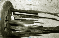
Credit: FDOT
Figure 16. Photo. Example of PT tendon failure due to macro-cell corrosion—Niles Channel bridge in Florida after 13 years in service.

Credit: FDOT
Figure17. Photo. Example of PT tendon failure due to macro-cell corrosion—Sunshine Skyway bridge in Florida after 13 years in service.
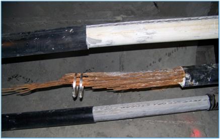
Figure 18 . Photo. Example of PT tendon
failure due to macro-cell corrosion—Verina-Enon bridge in Virginia after 17 years in service.
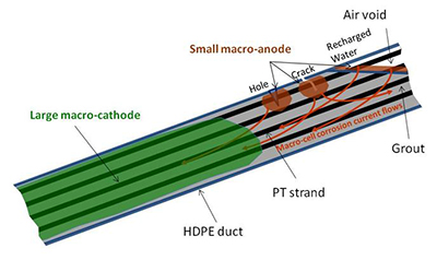
Figure 19. Illustration. Macro-cell corrosion mechanism in PT tendon.
Although the electrochemical reactions discussed are the same for any corroding steel in an aerated environment, the macro-anode and macro-cathode are physically separated, and their surface areas are much larger than ordinary micro-cell corrosion that consists of numerous tiny alternating anodes and cathodes. Consequently, intense corrosion can take place at the macro-anode by figure 10 and reduction of electrons at the macro-cathode by figure 11.
An Evans diagram (or E-log i diagram) illustrates how an anodic polarization diagram of a metal intersects with its cathodic polarization diagram. The intersection of two polarization diagrams determines the metal’s corrosion potential and corrosion current density. Figure 20 shows four E-log i plots that describe several corrosion potential-corrosion current density relationships of active-passive metals, such as PT strands, depending on different anodic and cathodic behaviors. The four plots can be described as follows:
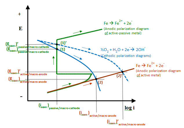
Figure 20. Graph. E–log i diagram describing different anodic and cathodic behaviors.
For macro-cell corrosion, cases (1) and (1') can relate to macro-cathode, while cases (2) and (2') can be related to macro-anode. The potential difference between any of them determines the driving force for macro-cell corrosion. In theory, electrical coupling between a macro-cathode in case (1') and a macro-anode in case (2') would yield the largest corrosion-induced damage as magnitude of corrosion current density determines level of damage, and the coupled condition yields the highest macro-cell current density ((icorr)'active/macro-anode − (icorr)passive/macro-cathode). More severe corrosion damage at the macro-anode can occur if surface area ratio of the macro-cathode to the macro-anode becomes large (i.e., small anode-large cathode situation).
In addition, apparent grout resistivity and grout resistance data were also collected to provide additional information about corrosion environment. Less grout resistance allows the corrosion current to travel further distances. As a result, a larger macro-cathode surface area can be involved in the corrosion process.
There were three types of test specimens employed in this study for each of three subtasks. They were designed to produce specific test results and, when analyzed together, provide comprehensive information regarding chloride threshold values.
The purpose of this subtask was to evaluate the effect of chloride concentration, stress level, and pH on corrosion of the PT strand. For this, corrosion potential and instantaneous corrosion rate of center wires exposed to various experimental conditions were measured.
A specially designed test cell was installed in the middle section of a 5-ft-long wire as shown in figure 21 and figure 22.
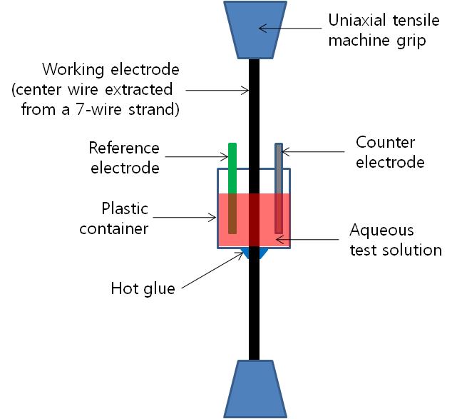
Figure 21. Illustration. Task 2.1 test setup for stressed wires.
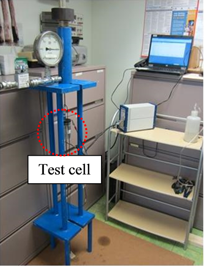
Figure 22 . Photo. Test cell for stressed wires.
The original wire surface condition including lubricants applied during the manufacturing process was untouched to produce the corrosion data from the strands in the as-received condition. Some wires were tested under no stress, and the others were prestressed at 60 percent of guaranteed ultimate tensile strength (GUTS). For the stressed wires, a custom-made loading frame equipped with a load cell and hydraulic pump was used to apply the target stress. The loading frame is shown in figure 21 and figure 22. For the unstressed wires, a wooden frame was used to hold the test cell in place vertically as shown in figure 23.
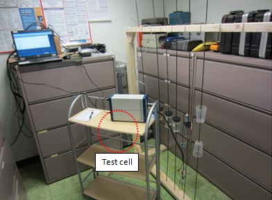
Figure 23. Photo. Task 2.1 test setup for unstressed wires.
The following test variables were employed to characterize electrochemical behaviors of stressed and unstressed wires at ambient temperature:
This specimen type was employed to understand the effect of chloride concentration, stress level, void, and crevice formed by adjacent wires on corrosion of single PT strands in chloride-contaminated grout. It has been observed that when actual PT strands corrode in the field, interstitial sites formed by twisted outer wires can encourage crevice corrosion.(14) Prestressing a strand also tightens all the interstitial spaces by stretching the wires and promoting capillary movement of water, thus enhancing corrosion activities there. A 12-inch single-strand specimen type was developed to measure corrosion rate on a short PT strand encased in hardened grout and a counter electrode.
Four rigid-loading frames were constructed to accommodate three 48-inch-long PT strands in each frame. A loading frame contained two stressed strands and one unstressed strand, as shown in figure 24.
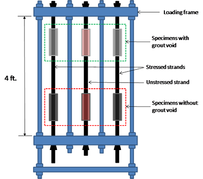
Figure 24 . Illustration. Task 2.2 loading frame for single-strand specimens.
Each strand had two mock-up clear polyvinyl chloride (PVC) ducts in the middle, as shown in figure 24. Therefore, a total of six mock-up tendon specimens (four stressed and two unstressed) were tested per loading frame. The upper duct specimens simulated tendons containing a grout void, and the lower ones simulated fully grouted tendons. Later, the lower and upper ducts were filled with a grout mix containing the same chloride concentration.
Details of the mock-up specimens are shown in figure 25. Inner diameter and length of each duct were 2.0 and 12 inches, respectively. The inner wall of the duct was surrounded with a cylindrical-shaped grade 316 stainless steel mesh, which served as the counter electrode for the linear polarization resistance (LPR) measurement. Such a confined test cell design was intended to capture a very low measurement current (i.e., nano-ampere (10-9 A) range) in (cathodic direction) and out (anodic direction) of the strand during the LPR measurement.
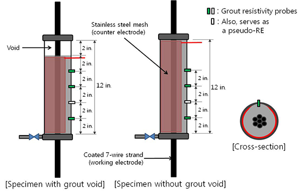
Figure 25 . Illustration. Single-strand test cells.
The duct also had four resistivity probes at 2-inch spacings. The probes were made out of 0.25-inch diameter and 1-inch-long mixed metal oxide titanium, and they were installed as illustrated in figure 26 and figure 27.
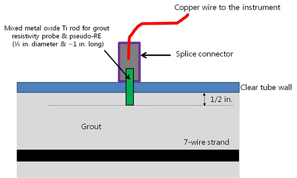
Figure 26. Illustration. Pseudo-reference electrode (PSE) probe.
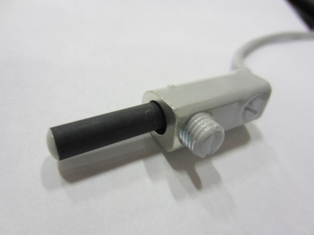
Figure 27. Photo. Actual PSE probe.
The probes were used to measure apparent grout resistivity using the Wenner four-pin method. The second probe from the duct bottom also served as the PSE for the corrosion potential measurement. The potential readings made with the PSE were converted to those with respect to a standard silver-silver chloride reference electrode (ACE). This is schematically presented in figure 28. Eight blank grout cylinders were used to measure corrosion potentials of PSEs in eight chloride concentrations.
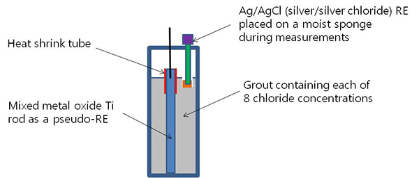
Figure 28. Illustration. PSE calibration cylinders.
An indirect potential measurement via a PSE was necessary to eliminate possible problems during the exposure testing when direct contact was made between grout and tip of the fragile ACE containing a liquid solution in a glass body.
The following variables were employed to characterize corrosion behaviors of stressed and unstressed PT strands:
After the counter electrodes and resistivity probes were installed in the ducts, the assembled duct specimens were placed at the fix positions along the strands, and the bottom openings between the strands and PVC caps were sealed with a silicon caulking material. The top openings were used as air vents during grout pumping. The strands were then installed in the loading frame. For the strands designated as stressed specimens, prestressing was done at 60 percent of GUTS from the upper end of the strands. For the unstressed ones, the strands were gently placed onto the loading frame using steel wedges. The target stress level was selected to avoid possibilities of overstressing while reflecting a typical working stress in the field PT bridges. After grout pumping, the top openings of the ducts were sealed with hot glue. Figure 29 and figure 30 show the stressing work, and figure 31 shows task 2.2 specimens prepared for grout installation.
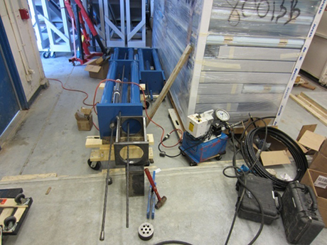
Figure 29 . Photo. Stressing of single-strand specimens.
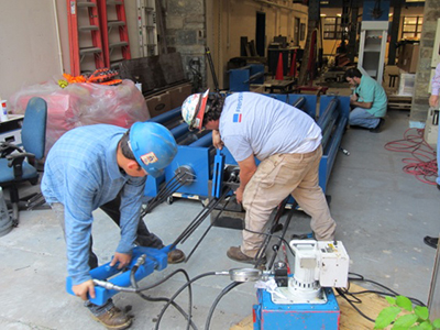
Figure 30. Photo. Stressing of multi-strand specimens.
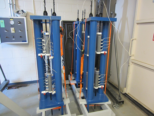
Figure 31. Photo. Fully assembled single-strand specimens.
The grouting work was completed in a single day. For each grout mix, six bags of the grout material, a predetermined amount of sodium chloride as listed in table 4, and 75 lb of distilled water were prepared in advance. The sodium chloride was dissolved in the mixing water just before mixing.
After pouring the dry grout powder into the grout mixer, mixing water was added (see figure 32). Once desirable grout consistency was achieved, the grout mix was pumped to the mock-up tendons (see figure 33). For the specimens without void, the duct was completely filled with the grout until it came out of the vent hole slightly. For those containing a void, 10 inches of the duct from the bottom was filled with the grout, and the remaining top 2 inches were left empty to simulate an entrapped air void. For each chloride concentration grout mix, casting was done with the same batch.
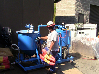
Figure 32. Photo. Grout mixing.
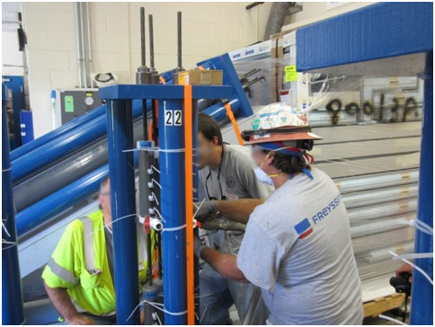
Figure 33. Photo. Grout pumping into a single-strand specimen
Random grout samples were taken from each mix to perform standard grout tests (see figure 34).
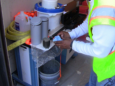
Figure 34. Photo. In-situ grout testing.
The 28-day grout compressive strength data are listed in table 5. Batch #9 was the only batch producing 28-day compressive strength below 8,000 psi, the advertised 28-day strength by the grout manufacturer.
Table 5. 28-day compressive strength data of grout mixes.
| Batch ID | Admixed Chloride Concentration by Weight of Cement (percent) | Cube Compressive Strength (psi) | |||
|---|---|---|---|---|---|
| 1 | 2 | 3 | Mean (psi) | ||
| Batch #1 | 0 | 10,040 | 10,290 | 10,400 | 10,243 |
| Batch #2* | 0 | 10,910 | 10,540 | 11,280 | 10,910 |
| Batch #3 | 0.08 | 8,780 | 10,140 | 10,580 | 9,833 |
| Batch #4 | 0.2 | 8,800 | 7,810 | 8,300 | 8,303 |
| Batch #5 | 0.4 | 10,060 | 9,220 | 9,080 | 9,453 |
| Batch #6 | 0.6 | 8,760 | 9,090 | 9,030 | 8,960 |
| Batch #7 | 0.8 | 9,420 | 9,500 | 9,020 | 9,313 |
| Batch #8 | 1.0 | 9,500 | 8,860 | 9,060 | 9,140 |
| Batch #9 | 2.0 | 6,350 | 5,810 | 7,350 | 6,503 |
Batch #9 exhibited normal fluidity (7 s) and wet density (126 lb/ft3). Mix and ambient temperatures were also within the recommended guidelines. Batch #9 was also the only one with specimens cured in plastic molds instead of cast iron molds. Plastic molds are known to reduce compressive strength compared to cast iron molds.
When the specimens were cured for 10 days, two baseline data collections were made at ambient condition for all 40 single-strand specimens. After that, 24 specimens (16 stressed and 8 unstressed) designated for the accelerated corrosion testing were placed in the smaller environmental chamber. The other 16 unstressed single-strand specimens were kept in the ambient condition to serve as controls as well as backup specimens, if necessary. In order to collect the data efficiently without disturbing the temperature and RH inside the chamber, all the lead wires from the specimens were organized in several bundles and were run to a data collection panel mounted on the exterior wall of the chamber (see figure 4 through figure 6).
The last specimen type was a large-scale multi-strand PT mock-up tendon. It was introduced to investigate the effects of chloride concentration, void, charging water, and macro-cell corrosion on PT strand corrosion. In this sub-task, reproduction of the worst PT corrosion problem caused by macro-cell corrosion was attempted using an innovative specimen design. Such a unique approach was necessary because conventional specimen configurations could not mimic the real macro-cell corrosion situation due to experimental limitations such as lab space and complexities involving fabricating long stressed tendon specimens in the confined environmental chambers. The multi-strand specimens were intended to simulate the principle of macro-cell corrosion mechanism as close as practical: macro-anode passing through a grout void with rechargeable water and macro-cathode embedded in normal grout. The intended macro-cathode was made with unstressed short strands surrounded by the intended macro-anode that was made with four stressed strands. Nearly equal surface areas were adopted for macro-anode and macro-cathode, thus surface effect (small macro-anode and large macro-cathode) could not be investigated in this study. This configuration also allowed comparing corrosion behaviors of stressed strands versus unstressed ones. This type of specimen could create more positive corrosion potential at the intended macro-cathode (case (1) or case (1') in figure 20) compared to the intended macro-anode (case (2) or case (2') in figure 20) and large driving force between them.
Each multi-strand specimen was 10 ft long and 6 inches in diameter. They were supported by a 25-degree inclined wooden support structure to simulate typical inclined tendons in the field. They contained four 10-ft stressed strands that served as a macro-anode and that were partially buried in the grout and five 7-ft unstressed strands that served as a macro-cathode and that were completely embedded in the grout. Both groups of strands were electrically isolated from each other with the exception of being coupled via an external toggle switch. Sufficient clearance among nine strands was maintained by three plastic circular plates with nine holes for the strands to run through. Four resistivity titanium probes identical to those used in task 2.2 specimens were installed at the 12-inch spacing along the 2 o’clock line starting from the lower anchor plate. The titanium probes were also used as the PSEs to measure the strand potentials at the probe locations. Figure 35 and figure 36 show specimen configuration and some of its details, respectively.
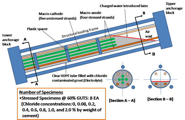
Figure 35 . Illustration. Task 2.3 multi-strand specimens.
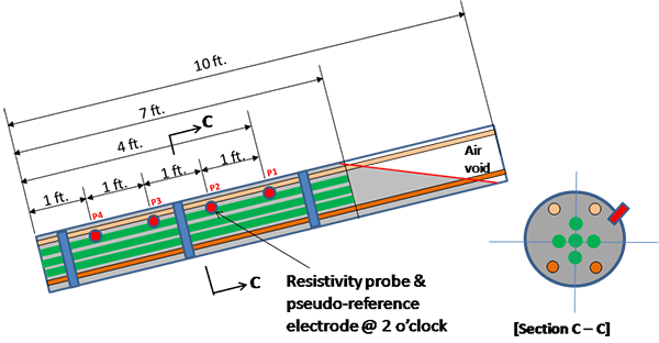
Figure 36. Illustration. Details of multi-strand specimens.
Figure 37 identifies the position of 12-inch-long strand segments with respect to the upper anchor plate. To monitor temperature inside specimens, two thermocouples were installed in the 0 percent chloride specimen placed in the smaller chamber and 1.0 percent chloride specimen placed in the larger chamber. The strand orientation was indicated as follows:
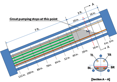
Figure 37. Illustration. Segment designation of multi-strand specimens.
A total of eight specimens were fabricated based on the following test variables:
Figure 38 shows some multi-strand specimens prepared for grouting.
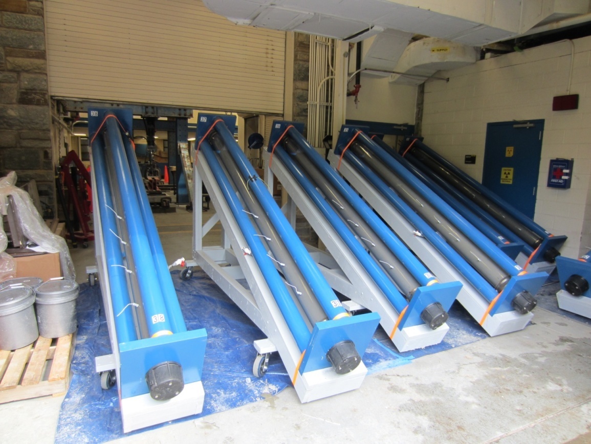
Figure 38. Photo. Fully assembled multi-strand specimens.
As described for task 2.2, eight chloride contaminated grout mixes were made per table 4. The fresh grout mix was pumped into the inclined duct until the horizontal void/grout interface reached 16 inches down from the upper anchor plate. This stopping point is indicated with a cross mark in figure 37. In this way, five unstressed strands were buried completely in the grout, and four stressed ones were partially embedded in the grout such that the top 18.5-inch section of two upper stressed strands (TL and TR in figure 37) and the top 13.5-inch section of two lower stressed strands (BL and BR in figure 37) were exposed in the void. Figure 39 shows grouting work in progress. It should be mentioned that the first specimen containing 0 percent chloride started to leak in the bottom grout cap area when about 30 percent of fresh grout was pumped into the duct. As a result, the first batch was discarded, the leaky cap was replaced, and new batch of fresh grout was installed in the specimen.
As explained in task 2.2, three data collections following the 10-day curing were made at ambient condition before they were placed in the environmental chambers to commence the first H & H cycle. The smaller chamber housed two specimens having the lowest chloride concentrations, and the larger chamber had the other six specimens (see figure 4 through figure 6).
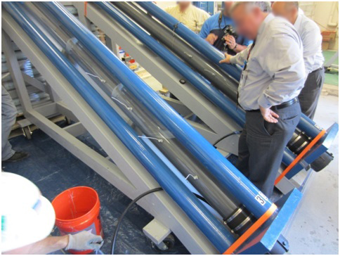
Figure 39. Photo. Grout pumping into a multi-strand specimen.
When an experiment was about to begin for a king wire in a particular test condition, a test cell mounted on the wire was filled with an aqueous test solution so that the immersed test area was 1.78 inches2, as listed in table 6. The test area is calculated as follows:
![]()
Figure 40. Equation. Calculation of surface area.
Where:
S = Surface area.
π= Constant (3.14).
d = Wire diameter.
l = Immersion depth.
Table 6. Test surface area used in this study.
| Category | Single PT Strand | Task 2.1 (Center Wire) | Task 2.2 (Single-Strand Specimens) | Task 2.3 (Multi-Strand Specimens) | |||
|---|---|---|---|---|---|---|---|
| Diameter (inch) | Surface Area (inch2) | Full | Void | Macro-Anode | Macro-Cathode | ||
| Outer six wires | 0.198 | ||||||
| Center (king) wire | 0.199 | ||||||
| Calculated test surface area | 52.3 | 3.14 × 0.199 inch × 2.85 inch = 1.8 inches2 | 1 strand × 1 ft/strand × 52.3 inches2/ft = 52.3 inches2 | 1 strand × 0.83 ft/strand × 52.3 inches2/ft = 43.6 inches2 | 4 strands × 8.7 ft/strand × 52.3 inches2/ft = 1,813.1 inches2 | 5 strands × 7 ft/strand × 52.3 inches2/ft = 1,830.5 inches2 | |
Note: Blank cells indicate no data were relevant to the cell.
After 24 h of initial conditioning in the quiescent test solution, the three-electrode LPR test was performed using the experimental setup shown in figure 21 through figure 23. The first step of a LPR measurement determined a corrosion potential of a wire specimen. Once the stable corrosion potential was obtained, Rp was determined through a series of step-wise potentiostatic polarizations. Finally, Rp was used to calculate an instantaneous nominal corrosion rate. For steel embedded in mortar or concrete, intensity of corrosion is usually classified into four corrosion rates, either by corrosion current density (µA/cm2) or by mils per year. These criteria are listed in table 7. Since test medium for task 2.1 is aqueous solutions, direct application of the criteria listed in table 7 is not feasible.
Table 7. Corrosion rate criteria.
| Degree of Corrosion | Corrosion Rate Criteria | |
|---|---|---|
| Corrosion Current Density (μA/cm2) | Corrosion Penetration Rate (mils/year) | |
| Negligible | ˂ 0.1 | ˂ 0.046 |
| Low | 0.1–0.5 | 0.046–0.230 |
| Moderate | 0.5–1.0 | 0.230–0.460 |
| High | ˃ 1.0 | ˃ 0.460 |
1 cm2 = 0.155 inch2
Corrosion performance of single-strand specimens was nondestructively monitored once a week using the following methods:
The condition of the strands in the void was occasionally inspected. Corrosion potential and instantaneous corrosion rate were measured using the setup shown in figure 41. Apparent grout resistivity data were collected as supplementary information using the Wenner four-pin method with 2-inch pin spacings as shown in figure 42.
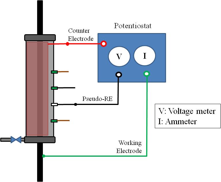
Figure 41. Illustration. LPR measurement for single-strand specimens.
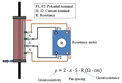
Figure 42. Illustration. Grout resistivity measurement for single-strand specimens.
Since test surface area should be known in order to calculate instantaneous corrosion rate, the following method was used to calculate PT strand surface area per unit length. The diameter of the outer wire was 0.198 inch, and the diameter of the center wire was 0.199 inch, as seen in figure 43.
![]()
Figure 43. Equation. Surface area of six outer wires.
As such, the following calculation was used to determine the surface area of the center wire:
![]()
Figure 44. Equation. Surface area of the center wire.
Where:
Sc = Surface area of the center wire.
dc = Diameter of the center wire.
Strictly speaking, the length of the outer wires should be longer than that of the center wire, but the additional length is ignored in this study to simplify the calculation.
![]()
Figure 45. Equation. Total surface area of seven wires.
As listed in table 6, surface areas of 52.3 and 43.6 inches2 were adopted for fully grouted specimens and those having a 2-inch void, respectively.
Task 2.3: Multi-Strand Specimens
Corrosion performance of multi-strand specimens was nondestructively monitored using the following methods once a week:
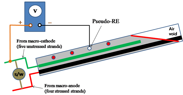
Figure 46. Illustration. Polarized potential measurement for multi-strand specimens.
Therefore, Imacro-cell was measured after a zero resistance ammeter (ZRA) was temporarily inserted in the circuit and then the toggle switch was turned off. This step is shown in figure 47.
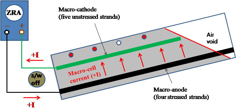
Figure 47. Illustration. Macro-cell corrosion current measurement for multi-strand specimens.
Later, the measured Imacro-cell was divided by macro-anode surface area of 1,813.19 inches2 from table 5 to calculate the macro-cell corrosion current density (imacro-cell) that is a normalized form of corrosion intensity. After the polarized potential and Imacro-cell were measured, ZRA was removed, and the electrical connection was left disconnected for several hours until the macro-anode and macro-cathode returned to their natural corrosion potentials. Once stable corrosion potentials were achieved, they were measured with respect to four PSEs. This step is shown in figure 48.
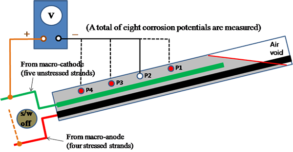
Figure 48. Illustration. Corrosion potential measurement for multi-strand specimens.
Grout resistance data were collected as supplementary information. Grout resistance was measured using four resistivity probes. The internal duct diameter with respect to resistivity probe spacing was too small to measure a valid apparent resistivity. As a result, the resistivity probes were used in two pairs to measure grout resistance in the upper and lower sections of the grouted duct as described in figure 49.
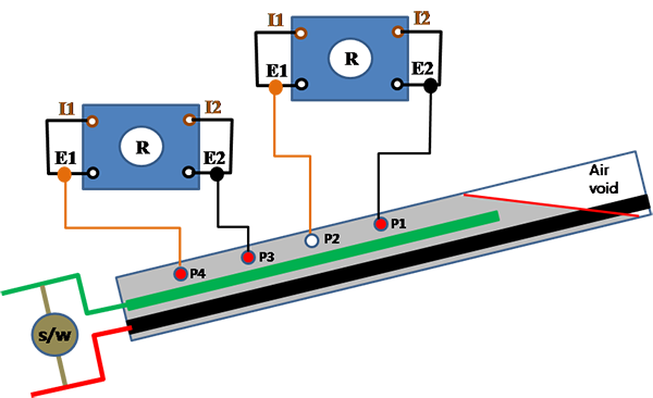
Figure 49 . Illustration. Grout resistance measurement for multi-strand specimens.
The PVC duct of a 0.8 percent chloride multi-strand specimen was abruptly cracked upon minor impact. It happened when a researcher tried to inspect the void condition of the specimen during the second F & D cycle. Emergency repair was made using a special wrapping tape to minimize the impact of cracks. Figure 50 and figure 51 show the specimen before and after repair.
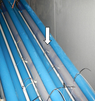
Figure 50. Photo. Cracked duct of 0.8 percent chloride multi-strand specimen before repair.
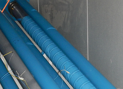
Figure 51. Photo. Cracked duct of 0.8 percent chloride multi-strand specimen after repair.
In order to replicate the water collecting problem from external sources into the voided area of duct in the field PT bridges, a small volume of water was added to the void space in five single-strand specimens and all eight multi-strand specimens after approximately 4 months of accelerated corrosion testing as follows:
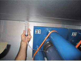
Figure 52. Photo. Water charging into a multi-strand specimen.
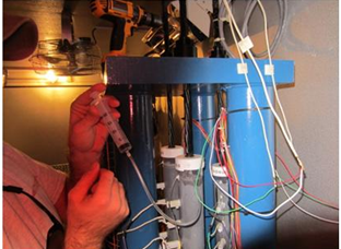
Figure 53. Photo. Water charging into a single-strand specimen.
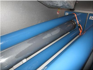
Figure 54. Photo. Multi-strand specimen 1 h after water charging.
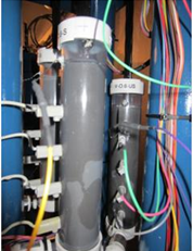
Figure 55. Photo. Single-strand specimen 1 h after water charging.
Researchers at the University of South Florida and FDOT also performed a similar laboratory study to investigate the same problem using a macro-cell corrosion test setup between PT anchorage assemblies and strands.(18) They were able to produce marked current increases as shown in figure 56 upon repeated water charging events.
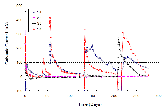
Figure 56. Graph. Relationship between water charging and macro-cell corrosion current jump.(18)
Right after water was added to the specimen voids, 4 0.5-inch-diameter holes were introduced to each of the 6 voided single-strand specimens, and 24 0.5-inch-diameter holes were introduced to one of the multi-strand specimens that was cracked and repaired. The specimens included the following:
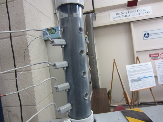
Figure 57. Photo. Drilled single-strand specimen.
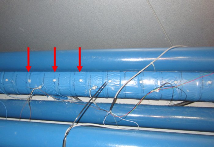
Figure 58. Photo. Drilled multi-strand specimen with 0.8 percent chloride.
At the completion of the 6-month data collection period, the specimens were taken out of the environmental chambers, and an autopsy was carried out. One day before performing the autopsy, final data collection was performed at ambient condition. Following the data collection, all of the stressed specimens were detensioned, and destructive autopsy work began.
The detensioned and originally unstressed single-strand specimens were cut out from their loading frames followed by the autopsy. As the first step, three grout powder samples along the length were extracted for chloride analysis at 0- to1-inch depth from each specimen (see figure 59). A total of 72 samples were taken from 16 stressed and 8 unstressed specimens. Then, a right angle grinder equipped with a diamond blade was used to split each specimen open (see figure 60). Every strand was extracted, and their grout/strand interfaces were examined and photographed (see figure 61). Some of the strands exhibited minor corrosion (see figure 62), and the others exhibited heavy corrosion (see figure 63). The as-extracted condition was documented on a mapping sheet. The extracted PT strands were dismantled, and the individual wires were cleaned with a scrubbing pad (see figure 64). Superficial rust stains could be removed by this method, but those having stubborn corrosion products associated with severe corrosion damage had to be cleaned further with an acid cleaning solution per ASTM G1 (see figure 65).(19) The cleaned wires were visually examined with occasional use of a magnifier.
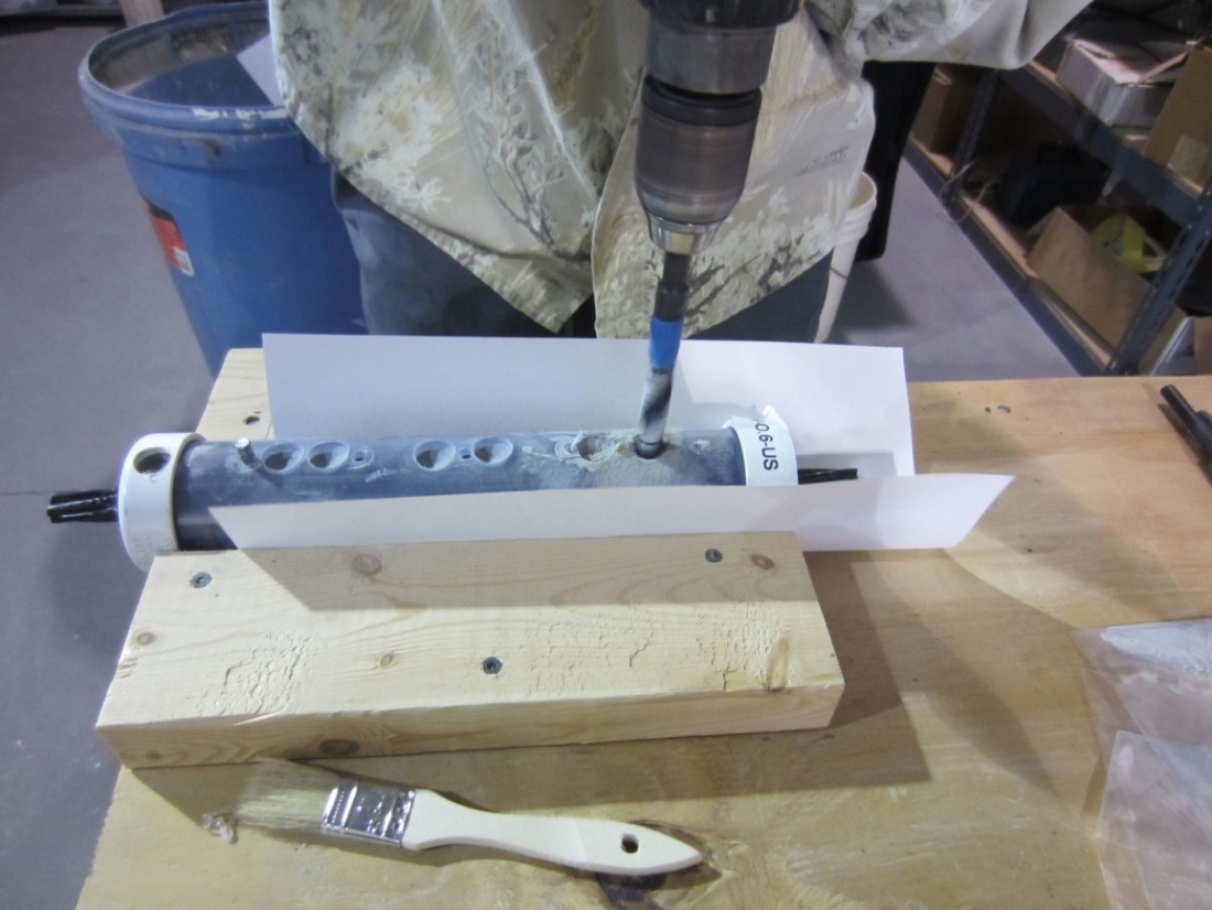
Figure 59 . Photo. Grout powder sampling from a single-strand specimen.
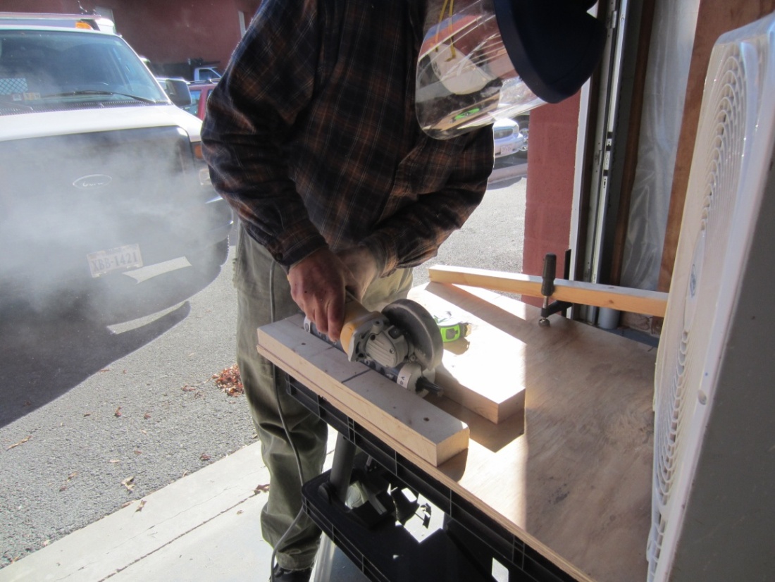
Figure 60. Photo. Splitting a single-strand specimen using a circular saw.
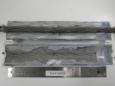
Figure 61. Photo. Single-strand specimen longitudinally cut in half.
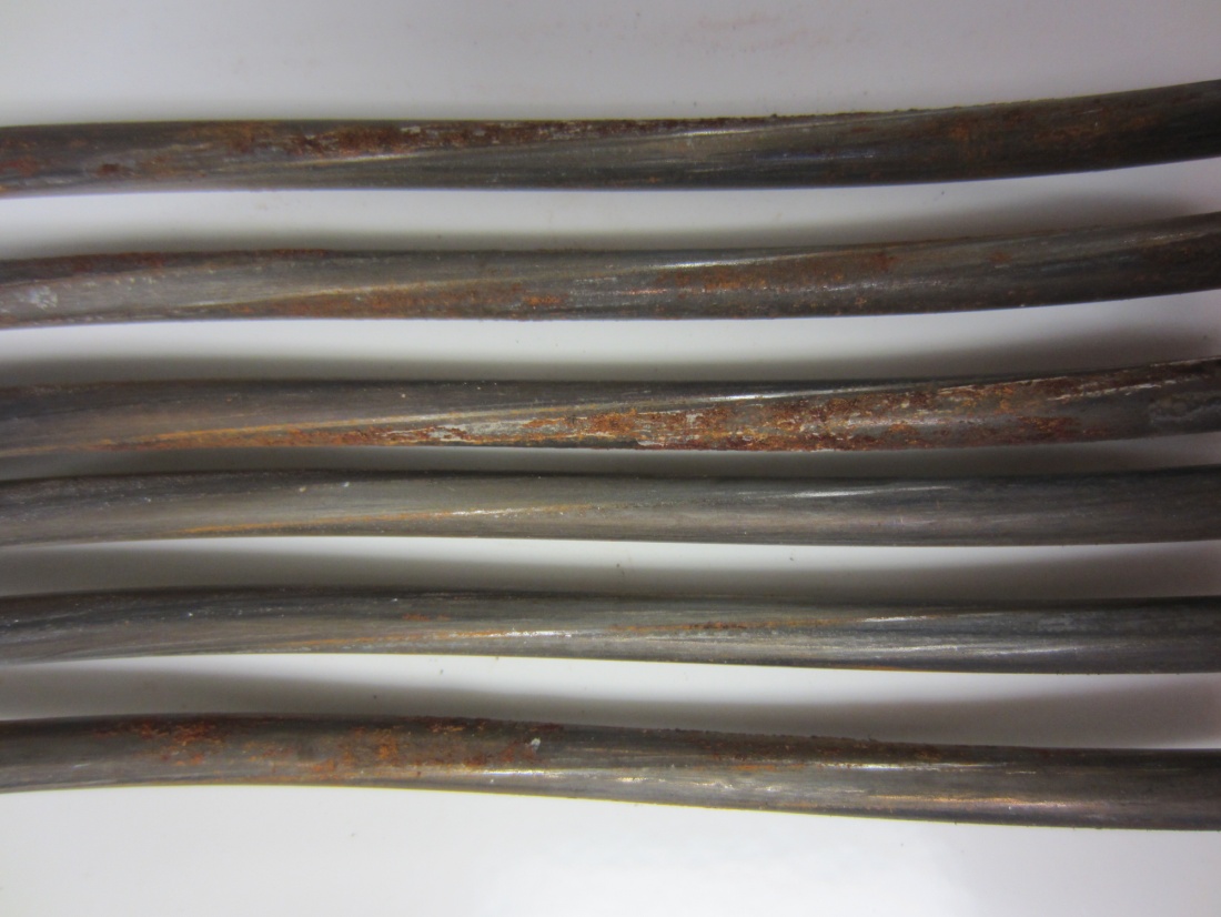
Figure 62. Photo. Example of superficial rust on the extracted wires.
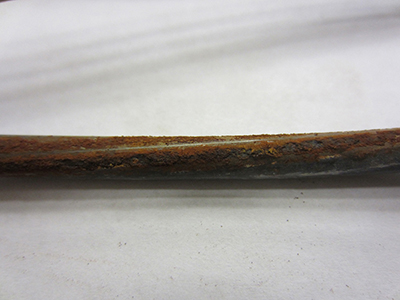
Figure 63. Photo. Example of heavy rust on the extracted wires.
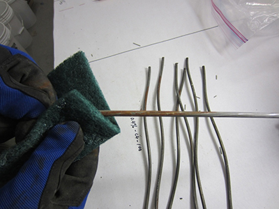
Figure 64. Photo. Cleaning individual wires using a scrubbing pad.
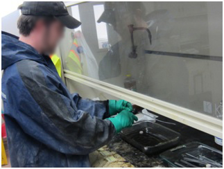
Figure 65. Photo. Acid cleaning of moderately to severely corroded wires.
After stress in a multi-strand specimen was released, the upper anchor plate was removed (see figure 66). Following it, 12 grout power samples per specimen were taken along the 3 and 9 o’clock lines by drilling at two depths (0 to 1 and 1 to 2 inches) and three locations (14, 48, and 96 inches) from the lower anchor plate (see figure 67). As a result, a total of 96 grout powder samples were extracted to determine spatial distribution of the admixed chloride in the multi-strand specimens.
As soon as grout sampling was completed, the destructive dismantling process started by cutting the clear duct along the 3 and 9 o’clock lines (see figure 68), removing the two duct halves, and chipping the grout away (see figure 69). Initially, great caution was exercised in anticipation of residual stress in the strands embedded in grout, but the stress dissipated quickly as the grout chipping work progressed from one specimen end. Some large grout pieces in direct contact with the strands were retrieved from the upper, middle, and lower sections of each specimen (see figure 70). These chunks were later used to collect powder samples at the strand imprints by carefully removing portions of the grout with a hammer and chisel to determine chloride concentrations at the grout/strand interface. Some grout fragments were also used to examine grout quality. After grout was completely removed, the strands were cut one by one near the lower anchor plate (see figure 71), and they were taken out of the loading frame (see figure 72). The removed strands were preserved in the smaller chamber which maintained a RH lower than 50 percent (see figure 73). After all the destructive work was completed, examination of the multi-strands started on a specially constructed autopsy table (see figure 74).
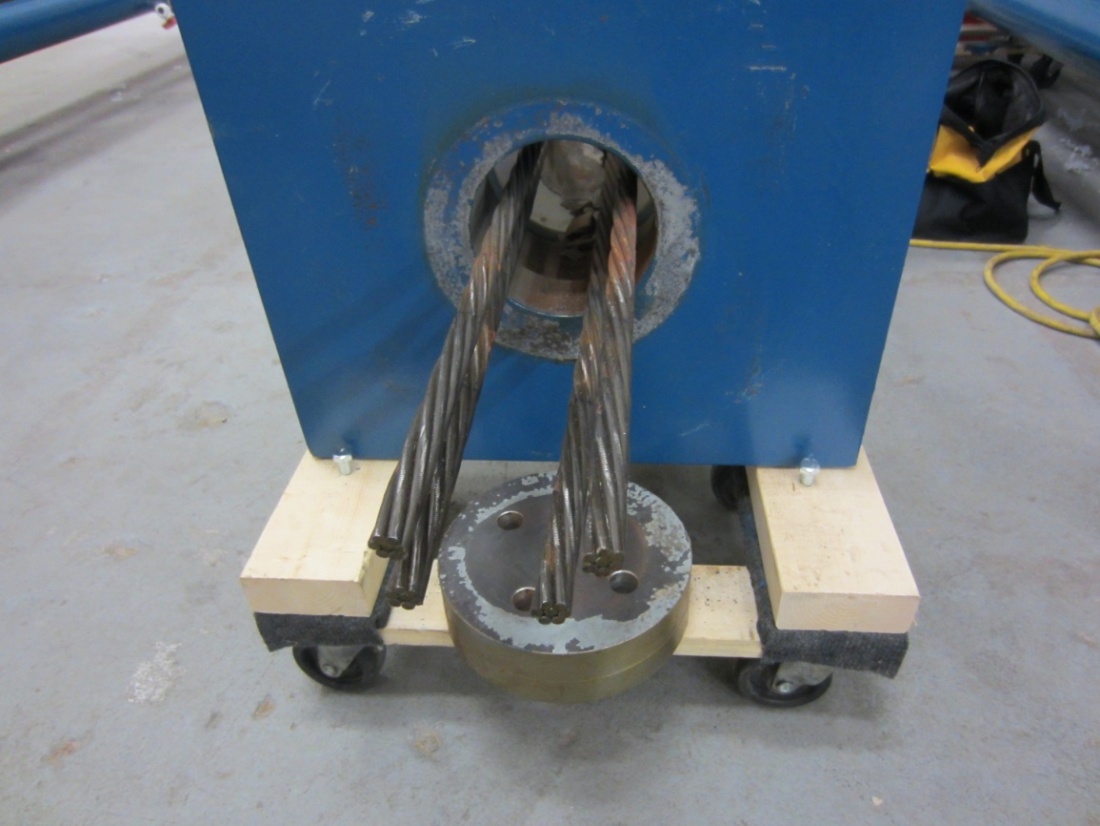
Figure 66. Photo. Removal of the upper anchor bearing plate of a multi-strand specimen.
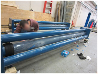
Figure 67. Photo. Grout powder sampling for chloride analysis from a multi-strand specimen.
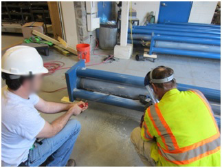
Figure 68. Photo. Cutting the clear duct to expose grout.
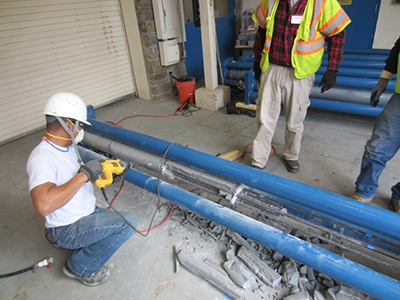
Figure 69. Photo. Chipping grout to expose PT strands.
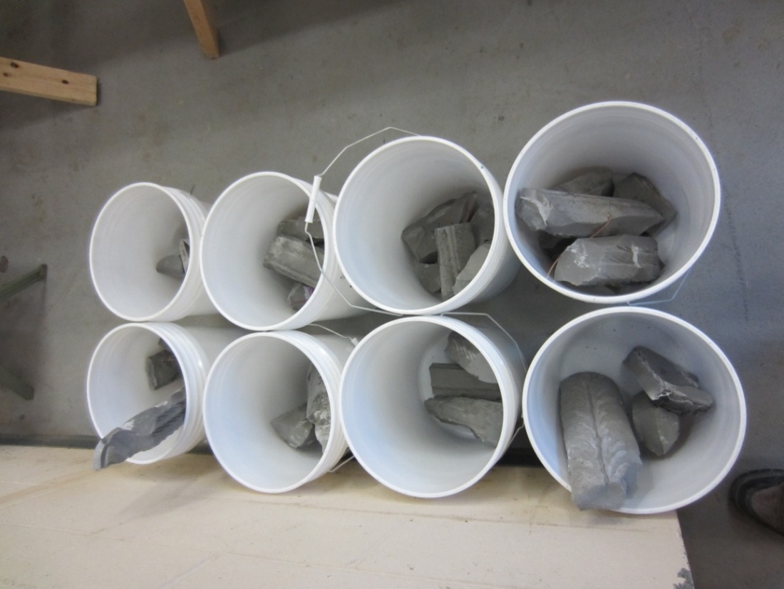
Figure 70. Photo. Retrieved grout pieces from multi-strand specimens.
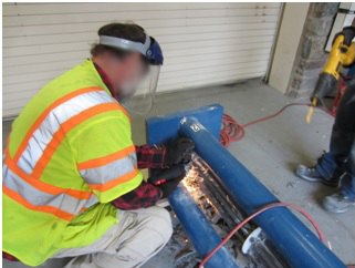
Figure 71. Photo. Cutting PT strands near the lower anchor bearing plate.
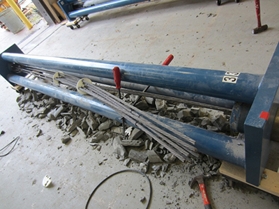
Figure 72 . Photo. Extracting a multi-strand bundle from a loading frame.
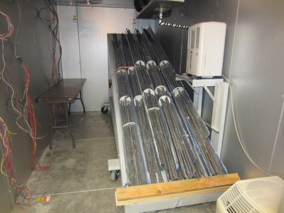
Figure 73. Photo. Storing the retrieved multi-strand samples in a chamber.
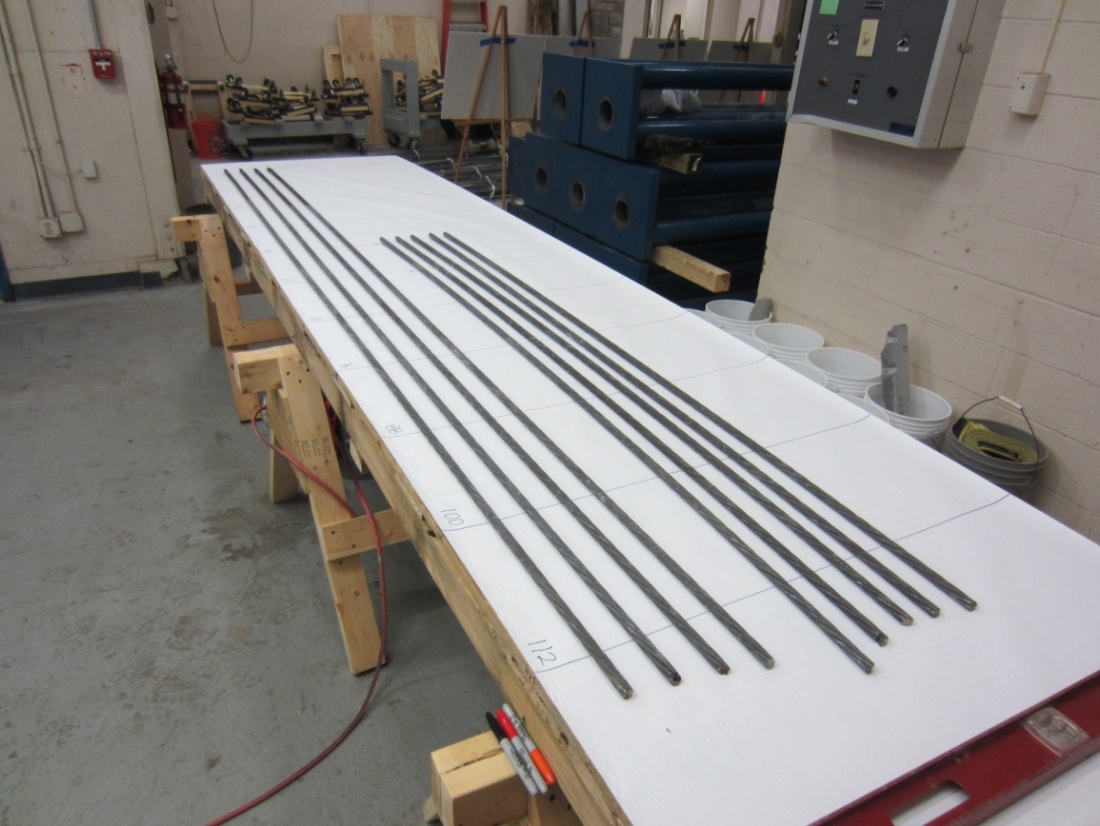
Figure 74. Photo. Inspecting PT strands removed from a multi-strand specimen on an autopsy table.
The as-extracted condition of each strand was carefully inspected and documented on a mapping sheet. As indicated in figure 37, the reference point in the mapping sheet was 16 inches, the mean distance to the void/grout interface from the upper anchor plate. From the reference point moving toward the lower anchor plate, 12-inch-long segments were marked on the stressed and unstressed strands. This is also depicted in figure 37. Every 12-inch segment that exhibited rust spots was identified on the mapping sheet. With this marking system, four stressed strand segments passed through the void/grout interface: two 4-to-16-inch segments of the BL and BR strands and two
16- to 28-inch segments of the TL and TR strands as labeled in figure 37. A total of eight strand segments close to the upper anchor plate were situated near the void/grout interface, and all the other stressed and unstressed strand segments were contained in the grout. It was observed during the autopsy that some of the interface segments exposed to unintentional sulfate ions exhibited more corrosion damage compared to the rest. This situation resembled severe corrosion failures observed in the defective tendons in service.
Many segments of the stressed strands exhibited signs of corrosion, and they were cut out for further examination (see figure 75). Individual wires removed from the cut-out segments were cleaned with a scrubbing pad first. Similar to single-strand specimens, the wires with stubborn corrosion products were cleaned further with an acid cleaning solution. The unstressed strands exposed to grout with moderate to high levels of chloride contamination often showed rust stains in the localized areas. Each unstressed strand with this condition was dismantled as one 7-ft-long piece, and the wires were also cleaned with a scrubbing pad. No significant corrosion damage requiring acid cleaning was observed on any of the unstressed wires (see figure 76).
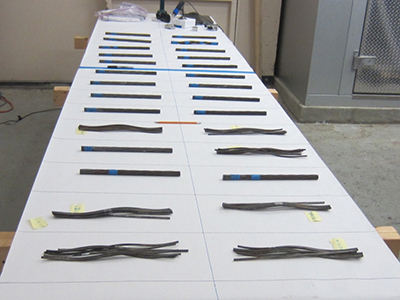
Figure 75. Photo. Several 12-inch-long cut-out segments exhibiting various corrosion conditions.
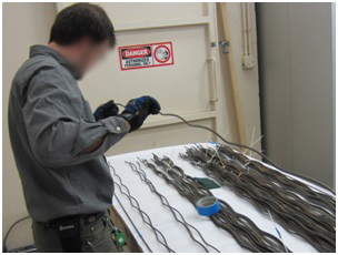
Figure 76. Photo. Cleaning and visual inspection of 7-ft-long unstressed strands.
The cleaned wires were first examined visually to classify them in two groups. The minor corrosion group included the wires exhibiting superficial corrosion or shallow pits (less than 2 mil deep). The wires that appeared to contain pits deeper than 2 mil were placed in the moderate to severe corrosion group. Most of the acid cleaned wires fell into the latter group.
Figure 77 shows a pit depth measurement in progress. The particular spot showed a pit depth of 13.5 mil. A digital pit depth gauge capable of measuring the lowest depth of 1.0 mil was used. A custom-made magnet-based measurement bed was a convenient means to hold the curved wire being measured steady in any orientation. Excessive section loss was measured with a digital micrometer as shown in figure 78.
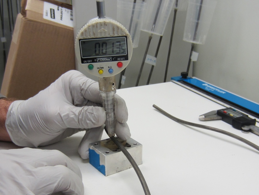
Figure 77. Photo. Pit depth measurement using a digital pit gauge.
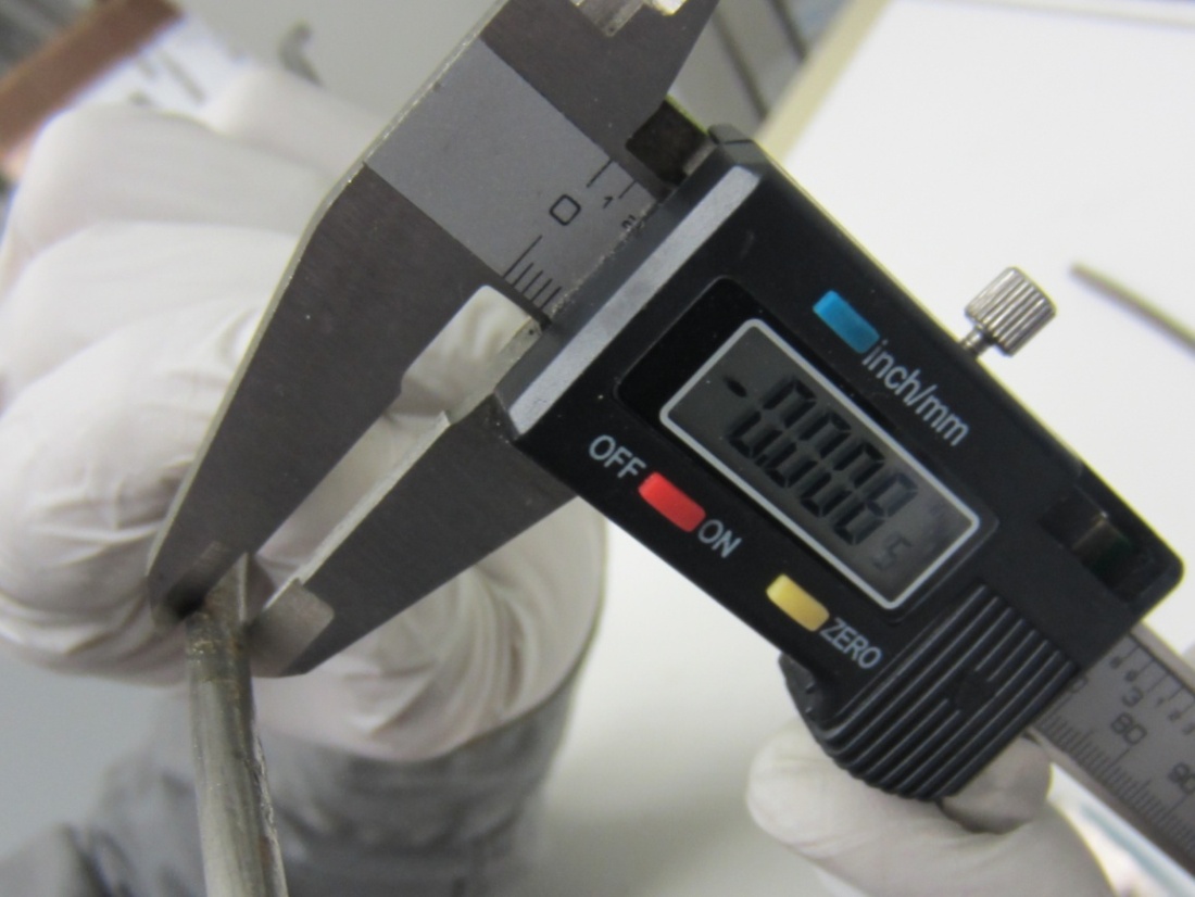
Figure 78. Photo. Section loss measurement in a severely corroded area.