U.S. Department of Transportation
Federal Highway Administration
1200 New Jersey Avenue, SE
Washington, DC 20590
202-366-4000


Skip to content
Facebook iconYouTube iconTwitter iconFlickr iconLinkedInInstagram

Federal Highway Administration Research and Technology
Coordinating, Developing, and Delivering Highway Transportation Innovations

 
REPORT
This report is an archived publication and may contain dated technical, contact, and link information
Back to Publication List        
Publication Number:  FHWA-HRT-17-013     Date:  February 2017
Publication Number: FHWA-HRT-17-013
Date: February 2017


Hydraulic Performance of Shallow Foundations for The Support of Vertical-Wall Bridge Abutments

APPENDIX C. CFD SHEAR STRESS AND VELOCITY DISTRIBUTIONS

This appendix contains graphical representations of the shear stress and velocity distributions for each CFD case, comparing the models with and without riprap.

These graphics compare plan views of bottom shear stress for a model without riprap (top) and with riprap (bottom) for cases 1 through 5. Generally, the shear stresses are higher in the area in the contracted section between the riprap aprons for the model with riprap compared with the model without riprap. The ratio of the two shear stresses decreases with increasing opening width going from case 1 to case 5. (1 lbf/ft2 = 47.88 Pa.)
1 lbf/ft2 = 47.88 Pa.
Figure 111. Graphics. Comparison of results of bed shear distribution for group 1.


These graphics compare plan views of bottom shear stress for a model without riprap (top) and with riprap (bottom) for cases 6 through 10. Generally, the shear stresses are higher in the area in the contracted section between the riprap aprons for the model with riprap compared with the model without riprap. The ratio of the two shear stresses decreases with increasing opening width going from case 6 to case 10. (1 lbf/ft2 = 47.88 Pa.)
1 lbf/ft2 = 47.88 Pa.
Figure 112. Graphics. Comparison of bed shear distribution for group 2.


These graphics compare plan views of bottom shear stress for a model without riprap (top) and with riprap (bottom) for cases 26 through 30. Generally, the shear stresses are higher in the area in the contracted section between the riprap aprons for the model with riprap compared with the model without riprap. The ratio of the two shear stresses decreases with increasing opening width going from case 26 to 30. (1 lbf/ft2 = 47.88 Pa.)
1 lbf/ft2 = 47.88 Pa.
Figure 113. Graphics. Comparison of bed shear distribution for group 6.


These graphics compare plan views of bottom shear stress for a model without riprap (top) and with riprap (bottom) for cases 31 through 35. Generally, the shear stresses are higher in the area in the contracted section between the riprap aprons for the model with riprap compared with the model without riprap. The ratio of the two shear stresses decreases with increasing opening width going from case 31 to case 31. (1 lbf/ft2 = 47.88 Pa.)
1 lbf/ft2 = 47.88 Pa.
Figure 114. Graphics. Comparison of bed shear distribution for group 7.


These graphics compare plan views of bottom shear stress for a model without riprap (top) and with riprap (bottom) for cases 36 through 39. Generally, the shear stresses are higher in the area in the contracted section between the riprap aprons for the model with riprap compared with the model without riprap. The ratio of the two shear stresses decreases with increasing opening width going from case 36 to case 39. (1 lbf/ft2 = 47.88 Pa.)
1 lbf/ft2 = 47.88 Pa.
Figure 115. Graphics. Comparison of bed shear distribution for the short extension slope.


These graphics compare plan views of bottom shear stress for a model without riprap (top) and with riprap (bottom) for cases 40 through 43. Generally, the shear stresses are higher in the area in the contracted section between the riprap aprons for the model with riprap compared with the model without riprap. The ratio of the two shear stresses decreases with increasing opening width going from case 40 to case 43. (1 lbf/ft2 = 47.88 Pa.)
1 lbf/ft2 = 47.88 Pa.
Figure 116. Graphics. Comparison of bed shear distribution for the long extension slope.


These graphics compare cross-section views of velocity for a model without riprap and with riprap for cases 1 through 5. Generally, the velocities are higher in the model with riprap compared with the model without. The differences in the velocity distribution decrease with increasing opening width going from case 1 to case 5. (1 lbf/ft2 = 47.88 Pa.)
1 lbf/ft2 = 47.88 Pa.
Figure 117. Graphics. Comparison of velocity distribution at central cross section for group 1.


These graphics compare cross-section views of velocity for a model without riprap and with riprap for cases 6 through 10. Generally, the velocities are higher in the model with riprap compared with the model without. The differences in the velocity distribution decrease with increasing opening width going from case 6 to case 10. (1 lbf/ft2 = 47.88 Pa.)
1 lbf/ft2 = 47.88 Pa.
Figure 118. Graphics. Comparison of velocity distribution at central cross section for group 2.


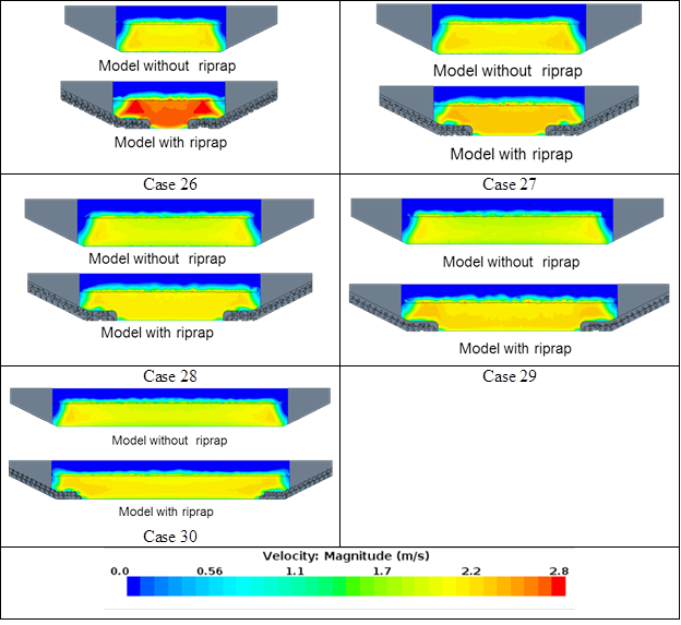
These graphics compare cross-section views of velocity for a model without riprap and with riprap for cases 26 through 30. Generally, the velocities are higher in the model with riprap compared with the model without. The differences in the velocity distribution decrease with increasing opening width going from case 26 to case 30. (1 lbf/ft2 = 47.88 Pa.)
1 lbf/ft2 = 47.88 Pa.
Figure 119. Graphics. Comparison of velocity distribution at central cross section for group 6.


These graphics compare cross-section views of velocity for a model without riprap and with riprap for cases 31 through 35. Generally, the velocities are higher in the model with riprap compared with the model without. The differences in the velocity distribution decrease with increasing opening width going from case 31 to case 35. (1 lbf/ft2 = 47.88 Pa.)
1 lbf/ft2 = 47.88 Pa.
Figure 120. Graphics. Comparison of velocity distribution at central cross section for group 7.


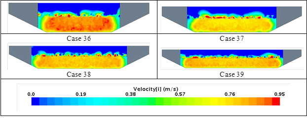
These graphics compare cross-section views of velocity for a model without riprap and with riprap for cases 36 through 39. Generally, the velocities are higher in the model with riprap compared with the model without. The differences in the velocity distribution decrease with increasing opening width going from case 36 to case 39. (1 lbf/ft2 = 47.88 Pa.)
1 lbf/ft2 = 47.88 Pa.
Figure 121. Graphics. Comparison of velocity distribution at central cross section for short extension slope.


Graphic compares cross-section views of velocity for a model without riprap and with riprap for cases 40 through 43. Generally, the velocities are higher in the model with riprap compared with the model without. The differences in the velocity distribution decrease with increasing opening width going from case 40 to case 43. (1 lbf/ft2 = 47.88 Pa.)
1 lbf/ft2 = 47.88 Pa.
Figure 122. Graphics. Comparison of velocity distribution at central cross section for long extension slope.


Federal Highway Administration | 1200 New Jersey Avenue, SE | Washington, DC 20590 | 202-366-4000
Turner-Fairbank Highway Research Center | 6300 Georgetown Pike | McLean, VA | 22101