Alternative Intersections/Interchanges: Informational Report (AIIR)
CHAPTER 3. MEDIAN U-TURN INTERSECTION
3.1 INTRODUCTION
One potential treatment to balance intersection congestion and safety problems is the MUT intersection. This design has been used extensively in Michigan for many years and has been implemented successfully in Florida, Maryland, New Jersey, and Louisiana in recent years. Figure 52 shows an MUT intersection in Michigan.
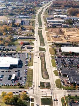
Figure 52. Photo. MUT intersection in a corridor in Michigan.(32)
The MUT intersection involves the elimination of direct left turns from major and/or minor approaches (usually both). Drivers desiring to turn left from the major road onto an intersecting cross street must first travel through the at-grade main intersection and then execute a U-turn at the median opening downstream of the intersection. These drivers then turn right at the cross street. Drivers on the minor street desiring to turn left onto the major road must first turn right at the main intersection, execute a U-turn at the downstream median opening, and proceed back through the main intersection. Figure 53 provides a schematic of a typical MUT geometric design, while figure 54 shows the left-turn movements. Elimination of left-turning traffic from the main intersection simplifies the signal operations at the intersection, which accounts for most of the benefits.
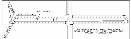
Figure 53. Illustration. Typical MUT design.
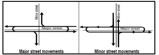
Figure 54. Illustration. MUT left-turn movements.
The MUT has been used widely in Michigan. Several highways in Michigan, particularly in the Detroit metropolitan area, were constructed with wide medians on wide rights-of-way. Many of these medians are 60 to 100 ft wide and were built decades ago in semirural areas. By the early 1960s, many of these highways had capacity problems because of interlocking left turns at conventional intersections. To address this capacity problem, the Michigan Department of Transportation (MDOT) and local highway agencies replaced the conventional intersections with MUT intersections. Today, there are more than 425 mi of boulevards, wide arterial multilane thoroughfare, with over 700 directional crossovers on MDOT highway system. Partial implementations or designs with similar concepts have appeared in Florida, Maryland, New Mexico, and Louisiana.
The MUT intersection is typically a corridor treatment applied at signalized intersections. However, the concept is also used at isolated intersections to alleviate specific traffic operational and safety problems. Levinson et al. recommended that the application of MUT intersections along the corridor should not be mixed with other indirect left-turn treatments or conventional left-turn treatments in order to meet driver expectancy. (32) This chapter concentrates on the treatment of an isolated intersection rather than on the treatment of a corridor to maintain consistency with the other chapters in this report. However, the corridor-based application of this intersection type should be kept in mind.
There are many variations of the basic MUT intersection design. Some of these variations include the following:
- Driveways or minor roads intersecting the arterial at the crossover.
- Unsignalized crossover intersections with either one or two U-turn lanes.
- Crossovers on the minor street in addition to or in lieu of the major street.
- Roundabouts instead of U-turn crossovers.
- Three-legged intersections.
Some of these variations add to the benefits provided by the basic MUT intersection design in some locations. While this chapter mentions some of these variations, the primary focus is on the most common MUT intersection design, which has four legs, a signalized main intersection, and signalized crossovers on the major road.
Another variation of the MUT intersection is the RCUT intersection. A RCUT intersection also uses U-turn crossovers to reroute some movements that would otherwise be made at the main intersection. In the case of RCUT intersections, the movements that are often rerouted are the minor street left turns, as with the MUT intersection, and minor street through movements. Because the RCUT intersection and the MUT intersection are so closely related, this chapter refers to RCUT intersections often. Chapter 4 contains a synthesis of knowledge on the RCUT intersection design and will refer back to this chapter often.
This chapter summarizes the advantages and disadvantages of the MUT intersection compared to conventional intersections where left turns are permitted from all approaches. The advantages of the MUT intersection include lower overall travel time, increased capacity at the main intersection, better progression on the major street, and enhanced safety. Pedestrians may enjoy some benefits with this design, and access management may be enhanced. Disadvantages may include higher right-of-way and construction costs and difficulties meeting driver expectations. The chapter also explores issues such as maintenance of traffic during construction and treatment of emergency vehicles. Much of the material in this chapter duplicates or is based on the FHWA TechBrief, Synthesis of the Median U-turn Intersection Treatment, Safety, and Operational Benefits.(33)
3.2 GEOMETRIC DESIGN CONSIDERATIONS
The MUT intersection performs well on arterials that have sufficient median width to accommodate the U-turn maneuver. This section discusses the geometry of the main intersection, U-turn crossovers, medians, and the spacing between the main intersections and crossovers. Because of Michigan experience with these intersections, MDOT typical design values are discussed throughout this section. In general, Michigan corridors with MUT intersections have median widths ranging from 60 to 100 ft. This design is used as a corridor treatment in Michigan, although it has been used successfully for isolated intersections. Figure 55 shows a design for a typical four-legged MUT intersection.
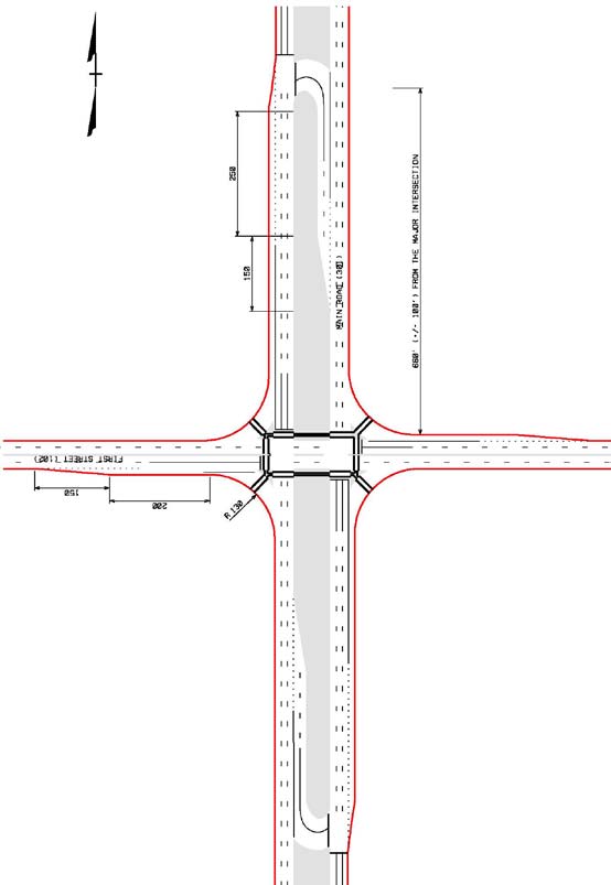
Figure 55. Illustration. Example of an MUT intersection.
At an MUT intersection, the design of the main intersection is similar to the design of a conventional intersection. The main intersection is designed for larger volumes of right-turn movements than a conventional intersection serving the same total volumes since the left-turning vehicles become right-turning vehicles. With this in mind, the intersection must be designed with right-turn bays of sufficient width and length to accommodate the volume of turning vehicles. Depending on the right-turn volume, dual right-turn lanes or an exclusive right-turn lane and an adjacent shared-use through and right-turn lane may be needed.
MDOT rarely uses channelized right turns at MUT intersections. Channelized right turns at an MUT intersection may require even more right-of-way, present a multistage pedestrian crossing, and create a more difficult driving maneuver for a driver turning right from the minor street and weaving over to use the U-turn crossover. At some MUT intersections (e.g., at partial MUT intersections), left turns from the side road are allowed as well as left-turn bays provided on the minor road approaches.
The MUT intersection has secondary intersections at each of the crossover locations. One-way crossovers with deceleration/storage lanes are highly recommended. Several studies (Scheuer and Kunde, Castronovo et al.; Taylor et al.) have found that one-way (directional) median crossovers provide better traffic operations and safety performance than two-way (bidirectional) crossovers.(34-36)
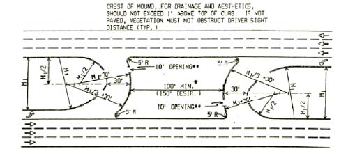
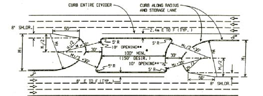
MDOT has developed design guidelines for directional median crossovers. (37) Figure 56 and figure 57 illustrate MDOT guidelines for designing directional median crossovers and show one-lane crossovers. In Michigan, it is customary for drivers of passenger vehicles to queue side-by-side in a 30-ft wide crossover and treat it as if it had two lanes. However, large trucks and other heavy vehicles typically use the entire width of the crossover. MDOT uses striped two-lane crossovers (with two lanes of storage leading up to the crossover) in some places. These crossovers are typically 36 ft wide.
Source: Michigan Department of Transportation Geometric Design Guide 670
Figure 56. Illustration. Directional crossover design on highway with curbs.(37)
Source: Michigan Department of Transportation Geometric Design Guide 670
Figure 57. Illustration. Directional crossover design on highway without curbs.
The AASHTO Green Book provides values for minimum median width based on the needs of U-turning design vehicles. (7) The design vehicle and number of opposing lanes directly govern the required median width at the median crossover junction. Median widths between 47 and 71 ft typically result from the choice of a large design vehicle and the desire to accommodate a U-turn maneuver of that vehicle without encroaching on outside curbs or shoulders. Assuming 12-ft-wide lanes and right-of-way limits that are 10 ft wide beyond the edge of the travelway, the right-of-way for Michigan boulevards can range from 139 ft for four-lane arterials to 163 ft for eight-lane arterials.
There are several ways to accommodate these MUT intersections if sufficient right-of-way is not available to accommodate a wide median. One method of reducing the median width is to allow vehicles to turn onto the existing or widened shoulder, which could have strengthened pavement. Another method is to add pavement outside the travel lane to allow the design vehicle to complete the U-turn maneuver and merge back into the traffic stream. The additional pavement is typically referred to as loon. Sisiopiku and Aylsworth-Bonzelet define loons as expanded paved aprons opposite a median crossover. (38) Figure 58 shows a schematic diagram of a loon design, and figure 59 is a photograph of a loon implemented in Wilmington, NC.
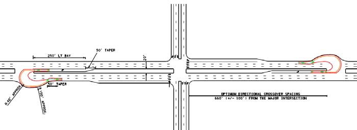
Figure 58. Illustration. Loon implementation for an MUT intersection.
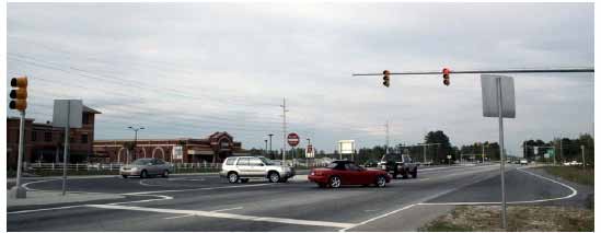
Figure 59. Photo. Example of loon implementation in Wilmington, NC.
Figure 60 shows a design in which the median widens in the vicinity of the crossover to better accommodate U-turns. The reverse curves used to accomplish the widening and narrowing should be gentle enough so as to not force drivers to execute unexpected sharp maneuvers as they proceed through the curves.
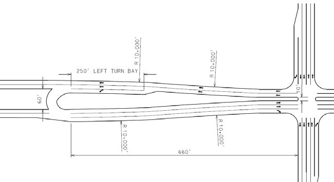
Figure 60. Illustration. Example of a transition from a wide median section to a narrow median section on MUT intersection corridors.(33)
Another way to use an MUT intersection design while keeping the main street median narrow is to place the U-turn crossovers on the minor street. Topp and Hummer showed that this variation may introduce travel time benefits compared to the common design with crossovers on the main road. (39) U-turn crossovers on the minor street mean that left turns from the main street are initiated with a right turn, which may violate driver expectations. As a result, adequate signing is critical in these cases.
The AASHTO Green Book recommends a distance of 400 to 600 ft for the minimum spacing between the median crossover and the main intersection. (7) MDOT recommends a distance of 660 ft ±100 ft for the median crossover from the MUT intersection. (37) The distances recommended by MDOT were established to accommodate drivers desiring to turn left from the crossroad. The longer distance facilitates the completion of the U-turn maneuver at the median crossover and subsequent right-turn maneuver at the intersection of the major road and cross street for a 45 mi/h posted speed limit on the major road. The Access Management Manual recommends an access spacing of 660 ft on minor arterials and 1,320 ft on principal arterials between consecutive directional median openings on divided highways. (40)
Designers should consider several issues when determining the distance from a main intersection to the median U-turn crossover. Longer distances to crossovers decrease probability of main road queues at the main intersection for the opposing direction of travel to block the crossover. They also provide more time and space for signs to be seen and read and for drivers to maneuver into the proper lane. Shorter distances to crossovers mean shorter driving distances and travel times and lower volumes at each crossover because each serve fewer driveways between the main intersection and the crossover. The selection of the spacing from the median crossover to the intersection is also a tradeoff between preventing spillback from the main intersection and the adverse impacts of additional travel for the left-turning vehicles.
Turn bays leading into U-turn crossovers are typically at least 250 ft long to provide adequate deceleration and storage. They may be longer when speeds are higher and U-turning demands are greater. In Michigan, to provide adequate storage, there are some MUT intersections where the turn bay for the crossover actually begins prior to the main intersection, at the prior crossover, or even before the prior crossover. Careful consideration of curb radii design, signing, and marking are needed at these locations so that drivers do not attempt to execute direct left turns at the main intersection.
3.3 ACCESS MANAGEMENT CONSIDERATIONS
The intent of an MUT intersection is primarily to serve through traffic on the major road. MUT intersections have the potential to provide a relatively high level of service (LOS) to through motorists on the main street over a wide range of demands. At the time of this report, no documented studies of the effects of MUT intersections on adjacent land users were identified. Inferences about the impacts on adjacent business can be drawn from NCHRP Report 420, which indicates that some land uses suffer economic losses with wide median installation. (12) This is particularly true for businesses such as gas stations and convenience stores that rely on pass-by traffic. The problems may be exacerbated when indirect left turns are needed to access some businesses. According to the NCHRP Report 420, during the planning of a project that involves creating or widening a median, the perceptions of adverse business impacts are typically worse than the ensuing reality. (12) There is no net community-wide economic impact resulting from the access changes. Nonetheless, the possibility exists that the installation of MUT intersections and concurrently much wider medians may create some business losses for some types of retail businesses.
Designers can develop MUT intersections that safely and efficiently manage access with minimum adverse impact to adjacent land users. In particular, designers have a great deal of flexibility in the placement and signalization of U-turn crossovers. On a corridor with MUT intersections, an agency may install traffic signal controls at any U-turn crossover without significantly changing the progression potential along the arterial. The signal offset for a new traffic signal at a crossover can be made to work with the existing progression band on the arterial. Signal visibility and queuing space should also be considered.
There is flexibility in locating U-turn crossovers when designing MUT intersections. Designers may generally locate a U-turn crossover within a range of distance from the main intersection without significantly reducing the efficiency of the overall intersection operation. Locating a planned crossover further from the main intersection so that it can also serve left turns into or out of an intersecting driveway or minor street may increase efficiency and safety of the whole corridor. The disadvantage of moving the crossover farther from the main intersection is that it creates longer travel distances for drivers wishing to turn left onto the crossroad at the main intersection.
Designers have a great deal of flexibility when locating driveways on an MUT intersection corridor. As with most high type intersection designs, no driveways should be allowed in close proximity to the main intersection. Driveways are also undesirable on the opposite side of the arterial from a loon. If a driveway is placed across from a loon, drivers may make wrong-way movements in the crossover.
There are mixed results for LOS and safety when driveways and side streets are located at the end of a U-turn crossover (e.g., in the loon). Such installations are common in the MUTs in Michigan and can lead to great efficiency. However, MDOT reports additional sideswipe collisions at some of these installations. MDOT has installed separate signal phases to serve the crossover and the driveway or side street in a few places, which limit the efficiency. (37) In similar circumstances, the North Carolina Department of Transportation (NCDOT) is attempting to obtain full control of access along the length of the loon on both sides of the road in its RCUT intersection applications to prevent access points at the loons.
3.4 TRAFFIC SIGNALIZATION TREATMENTS
The main intersection in an MUT design is typically signalized. Unsignalized MUT intersections exist in Michigan at low-volume cross streets on corridors with signalized MUT intersections or in developing areas where traffic volumes are expected to grow and a signal would eventually need to be installed. Agencies contemplating long-term unsignalized main intersections should strongly consider the unsignalized form of a RCUT intersection design as an alternative (see chapter 4).
A crossover at an MUT may or may not be signalized. Agencies should employ standard signal warrants in deciding whether to install traffic signal controls. In this case, the U-turn volume can be treated as the side road approach volume in the warrant criteria. A signal controller at a crossover is easy to coordinate with a signal controller at the main intersection. Therefore, agencies are able to be more aggressive in installing signals at MUT crossovers than they would at standard intersections where a new signal could have an adverse effect on the quality of progression on the major road.
Figure 61 shows the three signalized junctions at an MUT intersection, including the main intersection and the crossovers. The signals at the main intersection and the crossovers at a full MUT intersection design each have only two phases because there is no left-turning traffic (with a few exceptions as noted in section 3.2) and no exclusive pedestrian phases. Much of the efficiency gained at an MUT intersection stems from the two-phase signal operation.
Both directions of traffic on the arterial stop concurrently at an MUT intersection. This is similar to the signal at a conventional intersection. Because of the two-phase signals, the signal progression capabilities on an MUT intersection corridor are better than those of a corridor with conventional intersections. With good signal spacing and speeds, MDOT achieves sizeable two-way progression bandwidths on its MUT intersection arterials.
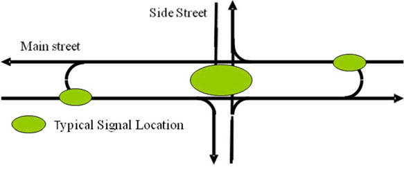
Figure 61. Illustration. Typical MUT intersection signal locations.
Figure 62 shows the signal phasing plan typically employed at an MUT intersection with signalized crossovers. Basically, the major street receives green indications during one phase, and the minor street and crossovers receive green indications during a second phase. To aid progression, MDOT starts the major street green phase approximately 7 s earlier at the crossover than at the main intersection and ends it approximately 7 s earlier. The internal offset depends on the distance to the crossover, the speed of the major street, and the expected size of the queue at the main intersection stop bar. Figure 63 shows a phasing plan with overlaps. MDOT also customarily staggers the start of the yellow and red signals for the minor street such that the yellow and red signals are displayed 1 or 2 s earlier at the near side of the major street than the far side, allowing the minor street through vehicles to clear out of the median. Figure 64 and figure 65 show the respective detector placements for the phasing scheme without and with phase overlaps, respectively. Table 6 and table 7 show the typical signal controller settings for these phasing schemes (figure 62 and figure 63).
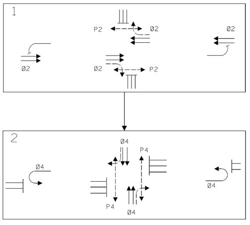
Figure 62. Illustration. Example MUT intersection phasing plan.
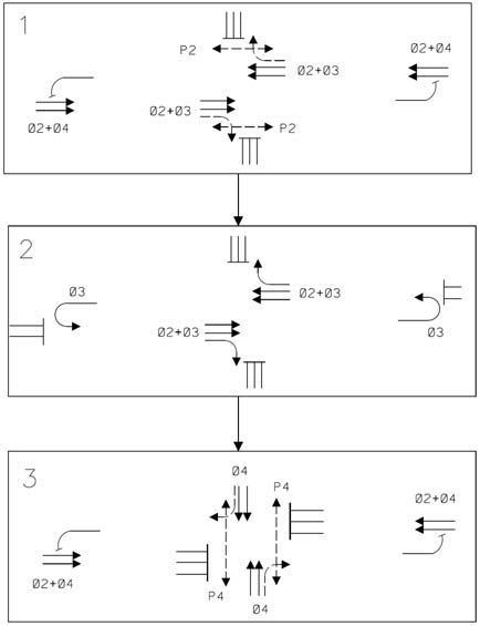
Figure 63. Illustration. Example MUT intersection phasing plan with overlaps.
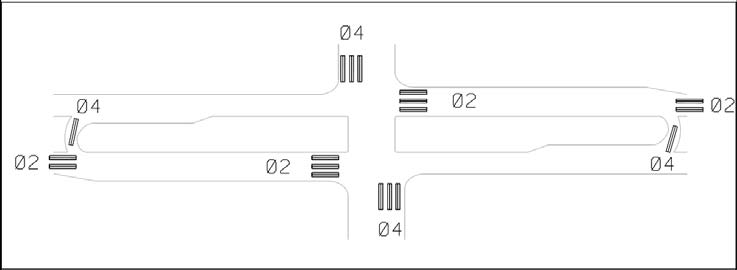
Figure 64. Illustration. MUT intersection detector placement.
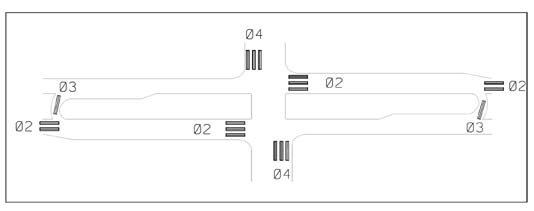
Figure 65. Illustration. MUT intersection detector placement for phasing with overlaps.
Signal timing at an MUT intersection can be straightforward. The agency chooses the cycle length and splits based on the demands at the main intersection with the signals at the crossovers merely mimicking the main intersection split. As noted in section 3.5, MDOT provides enough minimum green time to allow pedestrians to cross the major street to the median (e.g., a two-stage crossing). Actuated operation may provide the chance to start the major street green phase early at the main intersection or a crossover while preserving the background cycle for good progression.
Table 6. Typical signal controller settings for signal phasing shown in figure 62.
| |
Phase |
| |
1 |
2 |
3 |
4 |
5 |
6 |
7 |
8 |
| Min green |
|
15.0 |
|
5.0 |
|
|
|
|
| Max green |
|
40.0 |
|
30.0 |
|
|
|
|
| Passage (extension) |
|
2.0 |
|
3.0 |
|
|
|
|
| Amber |
|
4.0 |
|
4.0 |
|
|
|
|
| All red |
|
2.0 |
|
3.0 |
|
|
|
|
| Ped walk |
|
7.0 |
|
7.0 |
|
|
|
|
| Ped clearance |
|
14.0 |
|
14.0 |
|
|
|
|
| Recall |
|
M in green |
|
No |
|
|
|
|
M = Minimum.
Table 7. Typical signal controller settings for signal phasing shown in figure 63.
| |
Phase |
| |
1 |
2 |
3 |
4 |
5 |
6 |
7 |
8 |
| Min green |
|
15.0 |
4.0 |
5.0 |
|
|
|
|
| Max green |
|
30.0 |
20.0 |
30.0 |
|
|
|
|
| Passage (extension) |
|
2.0 |
4.0 |
3.0 |
|
|
|
|
| Amber |
|
4.0 |
4.0 |
4.0 |
|
|
|
|
| All red |
|
2.0 |
3.0 |
3.0 |
|
|
|
|
| Ped walk |
|
7.0 |
0.0 |
7.0 |
|
|
|
|
| Ped clearance |
|
14.0 |
0.0 |
14.0 |
|
|
|
|
| Recall |
|
M in
green |
No |
No |
|
|
|
|
Figure 66 shows possible signal locations at an MUT intersection. Note that where loons are employed, traffic signal control for the U-turn crossover must be moved back to provide room for the loon (see figure 59). MDOT does not report any problems with drivers not being able to detect and react to the signal indications in time to respond appropriately.
M = Minimum.
Note: Empty cells indicate that the phases are not used.
Figure 66. Illustration. Example of traffic signal locations at an MUT intersection.
3.5 SIGNING AND MARKING
Signing at an MUT intersection is critical to its success because the design may not meet the expectations of left-turning drivers unfamiliar with the intersection or intersection type. Figure 67 shows a possible signing plan for an MUT intersection. The large green guide sign for vehicles on the minor street was developed in Michigan. Prominent “No Left Turn” regulatory signs are also important at the main intersection.
Most of the signing installed by MDOT at MUT intersections are ground-mounted signs, as shown in figure 67. At many MUT and other intersections in Michigan, MDOT also provides overhead supplemental devices in the form of two backlit, four-sided case signs. These appear to unfamiliar traffic engineers as internally illuminated sign boxes with four faces displaying appropriate sign messages. A case sign is hung on span wire over the center of each of the points where the minor street intersects with a direction of the major street. The side of the case sign facing the median typically reads “No Turns.” The sides of the case sign facing the major street traffic and the minor street entering the intersection display a no left turn symbol. The side facing the wrong way traffic movement on the major street displays a wrong way symbol.
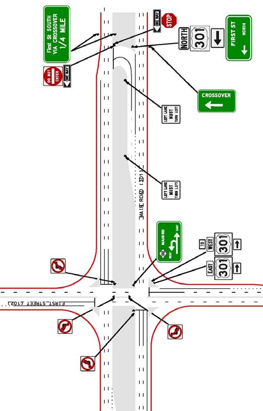
Figure 67. Illustration. Example MUT intersection signing plan.
There are guide signs other than those shown in figure 67 that can help motorists negotiate an MUT intersection. The “crossover” guide sign shown in figure 67 is rarely used by MDOT. The alternative sign shown in figure 68 is used by MDOT at the crossover when there are two U-turning traffic streams using one crossover.
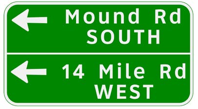
Figure 68. Illustration. Alternate crossover guide sign.
The sign shown in figure 69 is frequently used as an alternative to the “Crossover ¼ Mile” guide sign shown in figure 67. The sign in figure 69 provides guidance for left-turning and right-turning motorists. Figure 70 through figure 72 show examples of signing used at MUT intersections in Michigan.
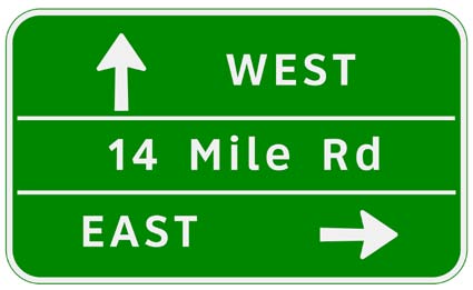
Figure 69. Illustration. Alternate major street advanced guide sign.
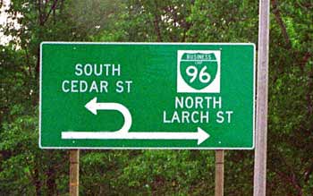
Figure 70. Photo. Example of minor road signing used at an MUT intersection in Michigan.
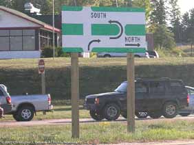
Figure 71. Photo. Example of alternative minor road signing used at an MUT intersection in Michigan.
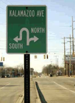
Figure 72. Photo. Example of major road signing used at an MUT intersection in Michigan.
Pavement marking standards used by MDOT provide guidance on marking the crossover area for both directional and bidirectional crossovers. Examples of the pavement marking standards used by MDOT are shown in figure 73 and figure 74.
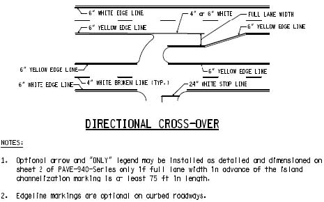
Source: Michigan Department of Transportation Geometric Design Guide 670
Figure 73. Illustration. Typical pavement marking at a directional crossover.(37)
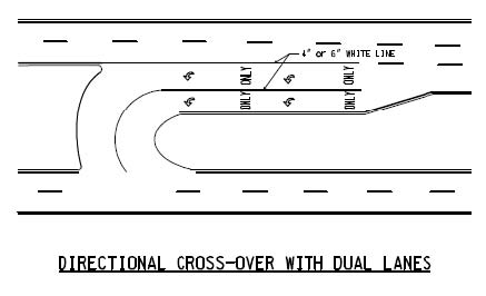
Source: Michigan Department of Transportation Geometric Design Guide 670
Figure 74. Illustration. Pavement markings at a directional crossover with dual lanes. (37)
3.6 ACCOMMODATION OF PEDESTRIANS, BICYCLISTS, DISABLED PEDESTRIANS, AND TRANSIT USERS
Crosswalks at an MUT intersection are at locations similar to a conventional intersection as shown in figure 75. The major street crossing can be made in one or two stages. A one-stage crossing (i.e., crossing both directions of the major street during one signal phase) is possible if the distance is not too long and if the necessary green time does not adversely impact traffic flow on the major road. At many MUT intersections in Michigan, these conditions have not been met, and a two-stage crossing of the major street is provided. In a two-stage crossing, a pedestrian crosses one direction of the major street during one signal phase and the other direction during a second signal phase often with some delay between the phases. Because there are only two signal phases and the cycle lengths are short, the amount of delay to a pedestrian due to the two-stage crossing is relatively small. If pedestrian signals and push-button controllers are provided, the devices need to be installed in the median as well as on the sides of the road.
Pedestrians with vision and cognitive impairments should find crossing an MUT intersection to be no more challenging than crossing a comparable conventional intersection. The cues that pedestrians with vision impairments rely on to cross intersections, such as the sound of traffic parallel to their crossing, are similar. Pedestrians should find the clear and direct crossing path relatively easy to use. All pedestrians should benefit from the simpler two-phase signal timing and the lower number of conflicting traffic streams than at a conventional intersection.
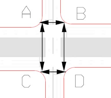
Figure 75. Illustration. Pedestrian movements at an MUT intersection.
Pedestrians crossing at an MUT intersection encounter fewer conflicting traffic streams than at a typical conventional intersection. Conflicts at conventional intersections are possible between left-turning traffic from the side road and pedestrians crossing the main street when the signal is in a phase in which the left-turn movement is permitted. Research shows that pedestrians who attempt to cross illegally during a leading protected left-turn phase can create conflicts with vehicles. By comparison, pedestrians at a full MUT intersection cross the main street during the minor street through and right-turn signal phase when the only conflicts possible are with minor street right-turning vehicles or major street right-turning vehicles making turns on red. Because of the fewer conflict points, a pedestrian crossing at a full MUT intersection may be safer than at a comparable conventional intersection. There are no empirical data available to support or reject this contention. An MUT intersection design along a corridor affords designers the flexibility to install pedestrian signals at midblock locations without adding much delay for through traffic on the major road with one condition that the pedestrian crossing is made in two stages.
Through and right-turning bicyclists encounter high green time percentages for their movements at full MUT intersections. Bicyclists desiring to make left turns from the side road face a choice of using pedestrian crosswalks to cross the major road and then the far side road or using the U-turn crossovers in a manner similar to drivers of motor vehicles. Bicyclists on the major road approaches who want to turn left onto the side road are faced with a similar decision. They can use the pedestrian crosswalks to cross the side road leg and then the far major road leg. However, the indirect left turn adds distance to the bicyclist’s travel. The U-turns may also present a hazard to bicyclists as vehicles executing U-turns have more difficulty staying in lanes, and larger vehicles exhibit greater off-tracking, which may cause vehicles to encroach into bicycle paths. Therefore, agencies should design MUT intersections to accommodate most left-turning bicyclists using the crosswalks. These treatments may include upgrading the sidewalks to shared-use paths while providing signing to direct bicycles to the shared pathway or providing signing emphasizing that direct left turns in the roadway are prohibited for bicyclists and drivers.
Analogous to pedestrians, transit users are not likely to be adversely impacted by the use of an MUT intersection instead of a conventional intersection. The design of the intersection does not necessitate locating bus stops further away from the main intersection, as with the DLT intersection discussed in chapter 2. Bus stops for through and right-turning buses likely work well on the far side of the main intersection or on the side street, respectively, where they create less delay for main road vehicles than if they are located on the approach to the intersection. Bus stops for left-turning buses may be more effective on the side road so that buses stop after making the U-turn and turning right onto the minor street. If there is more than one lane departing the intersection on the side road, this maneuver allows buses to easily get into the right lane in order to stop. A bus stop after the main intersection but prior to a U-turn maneuver may create a difficult weaving maneuver across the major street from a stop in order to use the crossover. On approaches to the main intersection where there is a loon provided for opposing direction U-turns, bus stops in the loon should be strongly discouraged to keep it free for vehicles using the crossover. A typical example of desirable bus stop locations is shown in figure 76.
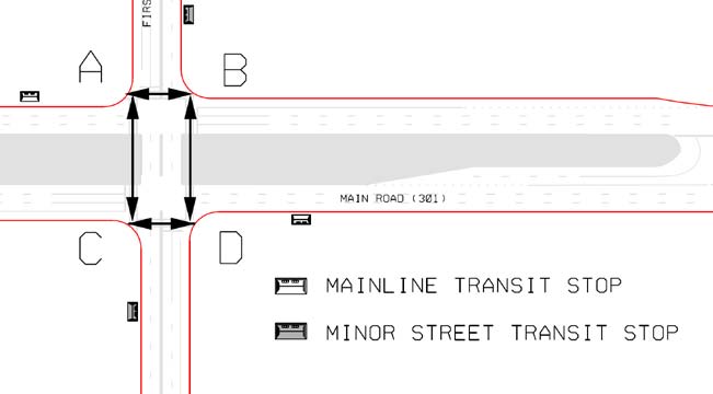
Figure 76. Illustration. Transit stop locations at an MUT intersection.
Transit users can benefit from more efficient traffic operations along an arterial in which MUT intersections are constructed to improve operations. Bus routes making left turns at an MUT intersection have to travel further and likely incur more travel time than a conventional intersection. MDOT has mitigated this in some places by allowing transit buses to make a direct left turn at the main intersection. They indicated this with a supplemental plaque that reads “Except Buses” under the “No Left Turn” sign at the main intersection. U-turn crossovers designed to accommodate large combination trucks without curb encroachments should also be able to accommodate standard transit and school buses.
3.7 OPERATIONAL PERFORMANCE
A possible advantage of MUT intersection design is the potential for improved operational performance. This section discusses situations in which the improved performance can be expected. The discussion is based on a review of research on the MUT intersection and also on results of an original simulation experiment to study the intersection design. Several studies have compared MUT intersections to conventional intersections. These studies have looked at the travel times, speeds, average number of stops, and capacity.
3.7.1 Previous Research Review
Savage studied the conversion of a five-lane roadway with a two-way left-turn lane (TWLTL) to an MUT intersection corridor in Michigan and found a 20 to 50 percent increase in the corridor capacity. (41) A study by Stover computed CLVs for the intersection of two six-lane arterial roads. (42) The effects of redirecting left turns were computed using these volumes. The provision of dual left-turn lanes on all approaches reduced CLVs by 12 percent compared to providing single left-turn lanes but still required multiphase traffic signal controls. The rerouting of left turns via directional crossovers and their prohibition at the main intersection reduced CLVs by 17 percent. Maki compared the MUT and the conventional TWLTL on four-lane and six-lane boulevards and found a 20 to 50 percent increase in capacity (throughput) for the MUT. (43) Figure 77 shows the LOS comparison between corridors with MUTs and conventional intersections.
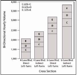
Figure 77. Graph. LOS comparison of divided highways.
Koepke et al. found that the directional crossover design provided about 14 to 18 percent more capacity than the conventional dual left-turn lane design. (44) The results of critical lane volume (CLV) analyses, after taking into account overlapping traffic movements, revealed reductions of about 7 to 17 percent in CLVs depending on the number of arterial lanes (six or eight) and the traffic mix. Lower CLVs translated into higher traffic flow capacity at the intersection.
Dorothy et al. evaluated traffic operational measures to study the differences in the performance of MUT intersections compared to the conventional TWLTLs. (45) A traffic network simulation model was used to simulate these situations for 1-hour periods. The simulated network had signals every 0.5 mi with the directional crossovers every 0.25 mi. A 60:40 split between the entering volumes on major road and cross street was assumed. When turning percentages were low, the crossovers were modeled as stop-controlled. With higher volumes, signal control was assumed in the model. The signal cycle was 80 s with a 60:40 distribution of green time for the major road phase and cross street phase, respectively. The median width varied from 40 to 100 ft. The key findings were as follows:
- When the left-turning traffic percentage was 10 percent, MUT intersections with signalized directional crossovers had lower left-turn total travel times than conventional intersections. The differences were 20, 40, and 150 s/veh at 30, 50, and 70 percent mainline saturation, respectively. Similarly, MUT intersections with signalized directional crossovers had lower left-turn total travel times than conventional intersections when the left-turning traffic percentage was 25 percent. The differences were 20, 30, and 70 s/veh at 30, 70, and 90 percent mainline saturation, respectively.
- The MUT intersections provided consistently lower network travel times compared to the five-lane TWLTL design.
- For low left-turning percentages, the directional median crossovers with stop control had approximately the same left-turn total time and network total time as the directional medians with signalized crossovers.
Reid and Hummer compared traffic operations along a typical arterial highway with MUT intersections to the arterial with conventional designs with TWLTL. (46) The analysis corridor was a 2.5-mi section of the northwestern highway corridor in Detroit, MI. The section consisted of five major signalized intersections with varied spacing from 1,600 to 3,500 ft and AADT ranging from 52,000 to 60,000 veh/day. CORSIM ® was used to simulate traffic performance, and Synchro ® was used to develop optimized signal timings. (21) Four time periods were considered in the analysis, including peak periods in the morning, midday, midafternoon (2–3 p.m.), and evening. Average measures of effectiveness were developed for a total of 48 CORSIM ® runs. The analysis indicated that the MUT intersection had the potential to significantly improve system travel times and speeds in the corridor during the busiest hours of the day and to not compromise system travel times during off peak periods. The corridor with MUT intersections showed a 17 percent decrease in total travel time within the study area network compared to a corridor with a TWLTL. Average speeds increased by 25 percent and the average number of stops increased for the MUT intersection compared to the TWLTL.
Reid and Hummer later used CORSIM ® to compare the traffic performance of seven unconventional arterial intersection designs, including the quadrant, MUT, RCUT, bowtie, jug-handle, split intersection, and DLT intersection. (20) They used turning movement volumes from existing isolated intersections in Virginia and North Carolina. Off peak, peak, and volumes corresponding to 15 percent higher than the peak volumes were examined. For each intersection type, 36 to 42 CORSIM ® simulation runs of 30-minute durations were analyzed. For MUT intersections, the CORSIM ® models used unsignalized U-turn crossovers for two-lane collector roads and signalized U-turn crossovers for four-lane collector roads. Entering volumes for the simulated intersections ranged from 4,500 to 7,500 veh/h. The MUT intersection produced significantly lower than average total travel times in comparison to the conventional intersection. The change in overall travel times for all movements through the intersection when compared to a conventional intersection was -21 to +6 percent during peak conditions. The overall change in the number of stops when compared to a conventional intersection was -2 to +30 percent during peak conditions.
Bared and Kaiser used CORSIM ® to study the traffic operational benefits of signalized MUT on a typical four-lane road intersecting a four-lane road. (47) The cross street left-turn movement was allowed at the main intersection, resulting in a three-phase signal. An acceleration lane was provided for the vehicles turning right onto the side road from the major road. These two features used in the study were different from the typical MUT intersection implementations in Michigan. Entering volumes at the intersections used in the simulations ranged from 2,000 to 7,000 veh/h. The key findings of the study were as follows:
- Compared to conventional intersections, considerable savings of travel time were observed for the U-turn design at higher entering flows (greater than 6,000 veh/h) with 10 and 20 percent left-turning volumes.
- On average, the proportion of vehicles stopping on the network was lower for the U-turn design. For the case with 10 percent left-turning volumes, vehicles in the U-turn design experienced 20 to 40 percent fewer stops. For 20 percent of left turns, a noticeable reduction in percent stops started when volumes reached approximately 4,500 veh/h.
- Providing an acceleration lane on the crossroad was recommended to improve traffic operational efficiency.
Topp and Hummer compared median crossovers on the cross street with median crossovers on the arterial highway for MUT intersections using CORSIM ® . (39) The left-turning volumes on the major road varied from 100 to 400 veh/h, the through volumes on the major road varied from 1,000 to 2,000 veh/h, the left turns on the cross street varied from 50 to 200 veh/h, and the through volumes on the cross street varied from 500 to 1,000 veh/h. The median crossovers were signalized wherever warranted. Results showed that the MUT intersection design with the U-turn movement located along the cross street reduced percent stops, total travel time, and delay for most of the volume combinations analyzed in comparison to the crossover on the arterial.
The Traffic Control Devices (TCD) Handbook suggests providing a left-turn phase if one of the following criteria is applicable: (48)
Based on volume, as follows:
- The number of left turns multiplied by the opposing conflicting volume in the peak hour exceeds 100,000 on a four-lane street or 50,000 on a two-lane street.
- The left-turn peak hour volume is greater than 90 veh/h or 50 veh/h on streets with through traffic speeds over 45 mi/h.
- The number of vehicles per cycle per approach at the end of green during the peak hour is greater than two at pretimed signal-controlled intersections.
Based on delay, as follows:
- The left-turn delay is greater than 2.0 veh-h in the peak hour on the critical approach, provided there are at least two left turns per cycle during the peak hour, and the average delay per left-turning vehicle exceeds 35 s.
Based on crash experience, as follows:
- For one approach, the number of left-turn crashes is equal to or greater than four crashes in 1 year or six crashes in 2 years.
- For both approaches, the number of left-turn crashes is equal to or greater than 6 crashes in 1 year or 10 crashes in 2 years.
The criteria above not only applies to the determination of the need for a separate left-turn phase at a conventional signal-controlled intersection but also to the determination of the need for signal control at median crossovers to accommodate U-turns.
Overall, the literature showed that reducing the number of signal phases and redirecting the left-turning movement at an intersection as found in the MUT intersection provided significant benefits in terms of increased roadway capacity and reductions in travel time and vehicular delay when compared to conventional intersections.
3.7.2 Research Findings
VISSIM ® was used to gain further insights into the operational performance of the MUTs in comparison to conventional intersections. Two intersection geometric design cases of MUTs and conventional intersections were simulated. The two cases modeled were as follows:
- Case A = A full MUT: Intersection of a four-lane major road and a four-lane minor road with one lane crossover on the mainline. No left-turn movements were allowed from the minor road at the main intersection.
- Case B = A partial MUT: Intersection of a four-lane major road and a four-lane minor road with one lane crossover on the mainline. Left-turn movements were allowed from the minor road at the main intersection.
Table 8 shows the geometric design configurations that were simulated. The lane configurations and geometric features for the MUT and conventional intersections on both approaches of the major road were identical for each case. Similarly, the lane configurations and geometric features on both approaches of the minor road were identical for the two types of intersections. These two geometric cases were simulated under six sets of traffic volumes—low, medium, and high. The major and minor road splits were also varied for the six simulation cases. Therefore, a total of 12 unique VISSIM ® simulations were developed for the MUT, and an equal number of unique VISSIM ® simulations were developed for comparable conventional intersections. A U-turn volume of 10 veh/h and a right-turn volume of 300 veh/h were modeled on all approaches. The VISSIM ® simulation network was 1 mi long on the major and minor road approaches for the cases simulated. The base case simulations assumed no pedestrian activity at the intersection. The following constants were assumed in VISSIM ® for all simulated cases:
- Optimum fixed signal timing determined using Synchro ®. (21)
- Yellow times determined using ITE policy.
- All-red times determined using ITE policy.
- A total of 5 percent heavy vehicles on all legs.
- A total of 350-ft-long left-turn bays upstream of the displaced crossover junction.
- A total of 325-ft-long left-turn bays downstream of the displaced crossover junction.
- A 0.5-mi network size in each direction from the main intersection.
- Single right-turn bays on the mainline.
- Right-turn on red allowed at each signal, no left-turn on red allowed.
- A signal at each DLT crossover.
- A 40-ft median width on mainline.
- Undivided side street.
- A 45 mi/h desired speed on mainline.
- A 25 mi/h desired speed on side streets.
- Saturation headway of approximately 1,900 veh/h/lane (alpha = 3 and beta = 2).
- No bus stops.
Table 8. Volumes for MUT intersection geometric design configurations for VISSIM ® simulations of cases A and B.
| Geometric Cases |
Set |
Major 1 Road |
Major 2 Road |
TotalMajor (Both Approaches) |
Minor (Each Approach) |
TotalMinor (Each Approach) |
Major/Total Major |
Total Minor/Total Intersection |
| Left |
Through |
Left |
Through |
Left |
Through |
| 2-lane major 2-lane minor 1-U turn |
1 |
100 |
2,100 |
100 |
2,100 |
5,020 |
10 |
750 |
1,070 |
0.50 |
0.26 |
| 2 |
110 |
2,090 |
154 |
1,386 |
4,350 |
10 |
750 |
1,070 |
0.60 |
0.29 |
| 3 |
110 |
2,090 |
148 |
632 |
3,590 |
10 |
750 |
1,070 |
0.75 |
0.34 |
| 4 |
150 |
1,800 |
150 |
1,800 |
4,520 |
90 |
950 |
1,350 |
0.50 |
0.35 |
| 5 |
300 |
1,000 |
300 |
1,000 |
3,220 |
200 |
1,450 |
1,960 |
0.50 |
0.44 |
| 6 |
100 |
650 |
100 |
650 |
2,120 |
450 |
1,750 |
2,510 |
0.50 |
0.26 |
For case A, the MUT intersection had two through lanes, one left-turn lane, and one right-turn lane per approach for the mainline approaches and two through lanes and one right-turn lane per approach for the side street approaches. The left-turn lane on the mainline upstream of the median crossover had a length of 250 ft, and the right-turn bay on the side street had a length of 200 ft. No acceleration lanes were provided for right-turning from the side street. The median separating the opposing through lanes was 10 ft wide. The comparable conventional intersection had similar geometric features and dimensions as the MUT described above on all four approaches. The VISSIM ® simulations results are shown in figure 78. The MUT intersection showed an increase in throughput of 15 to 40 percent in comparison to conventional intersections. The average intersection travel time for the conventional intersections was significantly higher than the MUT intersections in saturated conditions.
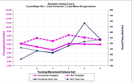
Figure 78. Graph. Throughput and travel time comparisons for geometric design case A.
For case B, the partial MUT intersection had two through lanes, one left-turn lane, and one right-turn lane per approach for the mainline approaches and two through lanes, one left-turn lane, and one right-turn lane per approach for the side street approaches. The left-turn lane on the mainline upstream of the median crossover had a length of 250 ft, and the left-turn and right-turn bays on the side street had a length of 200 ft, respectively. No acceleration lanes were provided for right-turning from the side street. The median separating the opposing through lanes was 10 ft wide. The comparable conventional intersection had similar geometric features and dimensions as the MUT described above on all four approaches. The VISSIM ® simulations results are shown in figure 79. The throughput at an MUT intersection was 10 to 25 percent higher compared to conventional intersections. The average intersection travel times for the conventional intersections were significantly higher than the MUT intersections in saturated conditions.
In summary, the MUT intersections were better suited for heavy through traffic volumes on the major road and side streets with moderate balanced left turns from the major road and side streets.
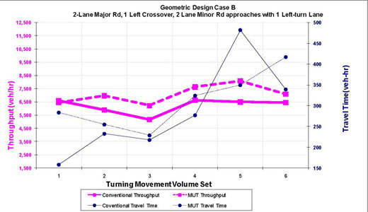
Figure 79. Graph. Throughput and travel time comparisons for geometric design case B.
3.8 SAFETY PERFORMANCE
Table 9, which is from the FHWA report entitled Signalized Intersections: Informational Guide, shows the number of conflict points at a four-legged signalized intersection (32 total) as compared to the MUT intersection (16 total). (49) The MUT intersection eliminates all crossing conflict points related to left turns and reduces the number of merge/diverge conflict points as well. Figure 80 shows the location of conflict points for an MUT intersection. Common crash types occurring at MUT crossovers are rear ends, angle, and sideswipe crashes. In the NCHRP Report 524, “Safety of U-Turns at Unsignalized Median Openings,” collected traffic conflict data were reported. For most types of median openings, conflicts involving major road vehicles having to brake for vehicles turning from the median opening onto the major road were the most common type of conflict. (50) The implementation of MUT intersections resulted in overall reductions in rear-end, angle, and sideswipe crashes by 17, 96, and 61 percent, respectively. (33)
Table 9. Comparison of conflict points for MUT and conventional four-legged intersection.
| Conflict Type |
Four-Legged Signalized Intersection |
MUT Intersection |
| Merging/diverging |
16 |
12 |
| Crossing (left turn) |
12 |
0 |
| Crossing (angle) |
4 |
4 |
| Total |
32 |
16 |
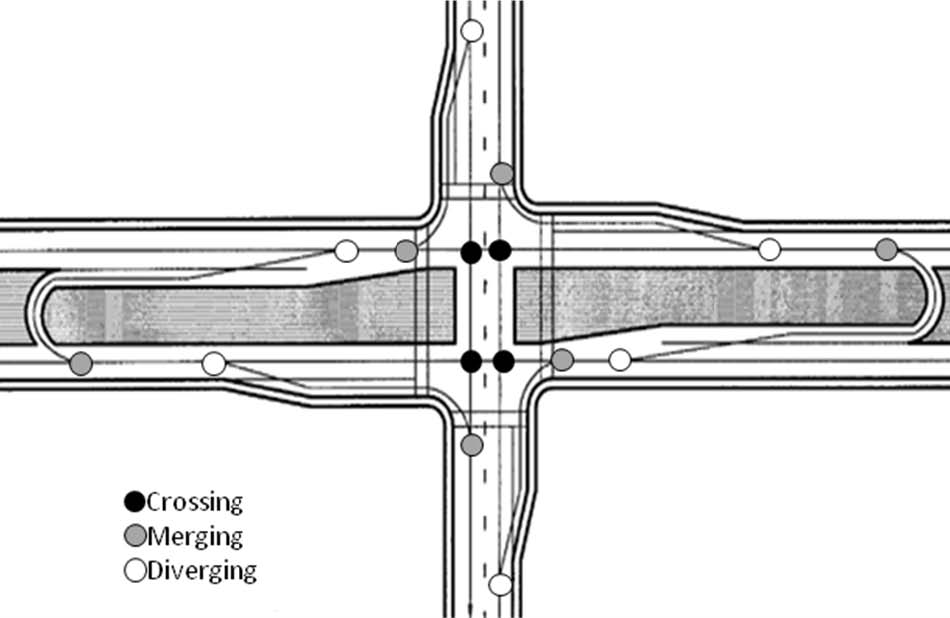
Figure 80. Illustration. Conflict point diagram for MUT intersection.
In NCHRP Report 524, both urban/suburban and rural median openings were analyzed. (50) Urban arterial corridors exhibited an average of 0.41 U-turn plus left-turn crashes per median opening per year. Rural arterial corridors experienced an average of 0.21. Kach compared the safety performance of conventional signalized intersections to MUT intersection locations in Michigan. (51) The study consisted of 15 MUT intersection locations and 30 conventional intersections. Analysis of crash data for the period revealed statistically significant lower crash rates for the MUT intersections for both corridor-wide and intersection-related data sets.
Castronovo analyzed the safety benefits of MUT intersections compared to conventional intersections as a function of traffic signal density. (52) Data were collected from approximately 125 boulevard segments. The analysis results indicated that as traffic signal density increased, the MUT intersection had increasingly lower crash rates than the conventional intersection.
Figure 81 shows the two types of median crossovers—bidirectional and directional. As discussed in section 3.2, a bidirectional crossover is an opening in the median for vehicles to make U-turns from either direction. The use of bidirectional crossovers creates additional points of conflict compared to the directional crossover shown in figure 81. In addition, an interlocking effect can be created if turning volumes are relatively large. This could create sight distance limitations and could lead to unpredictable driver behavior as drivers try to complete their U-turn maneuver when the paths are blocked.
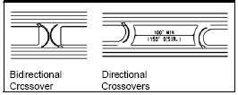
Figure 81. Illustration. Directional and bidirectional crossovers.
A directional crossover is considered to be a safer design because motorists at a properly designed directional crossover should not experience the interlocking effect found at medians with a bidirectional crossover. Several studies compared the crash experience of bidirectional, or conventional, crossovers with directional crossovers. For divided highway corridors without signals, the directional crossover had the same crash rates as bidirectional crossovers; however, for signalized corridors, the crash rate was lower when only directional crossovers are used. (53) Three studies showed that where existing bidirectional crossovers were replaced with directional crossovers, a reduction in crashes was typical. (34, 36, 43) Because replacement of a bidirectional crossover typically requires multiple directional crossovers to serve the same movements, all crossovers related to serving traffic wishing to turn left at the main intersection should be considered when estimating the impact of directional versus bidirectional crossovers or when comparing a conventional intersection design to an MUT intersection design.
Intersections with driveways or minor roads may be located at MUT crossovers. In NCHRP Report 524, safety at intersections on divided highways was analyzed. (50) The results were applicable to the situations where driveways or intersections were located at the median opening where left-turning vehicles from the main intersections were making U-turns. NCHRP 524 concluded that for urban arterial corridors, accident rates for directional median openings at three-legged intersections were about 48 percent lower than the accident rates for the equivalent conventional (bidirectional) median openings at three-legged intersections. Average accident rates for directional median openings at four-legged intersections were about 15 percent lower than for conventional four-legged intersections.
At crossovers where U-turns are permitted at the same time as right turns from a side street or driveway, the potential for conflicts exists and should be considered. Not allowing such driveways or side streets at crossover locations is one feasible option to reduce these conflicts, but there are demonstrable efficiency benefits associated with aligning crossovers with driveways or side streets in some situations. Separate signal phases for the U-turn and the right-turn movements are another option, but those would likely add delay and could cause collisions due to added queuing. To manage the conflicts, some agencies use signs (R10-16 in the MUTCD) directing the U-turn movement to yield to the right-turn movement. (8)
3.9 CONSTRUCTION COSTS
In a majority of the cases, construction of an MUT intersection has greater initial costs compared to a conventional signalized intersection. The MUT intersection significantly differs from a conventional intersection with respect to the U-turn crossovers and loons, which can have significant right-of-way costs. When the existing roadway has sufficient median width for construction of a U-turn crossover without a loon, the land acquisition costs are minimized. Land acquisition costs can increase significantly if a loon is needed and additional right-of-way is required, especially at the crossover and loon locations.
Items for mobilization, overhead lighting, pavement markings, and drainage are similar for an MUT intersection as compared to a conventional intersection. Relocation of utilities varies from intersection to intersection depending on existing conditions and therefore cannot be quantified.
There is more signing at an MUT intersection than at a conventional intersection. Turn prohibitions and directional signing for the traffic using the crossover for left-turn movements is a major part of that additional cost. If the median openings for the U-turns require signal control, then additional signals and mast arms are required at each crossover. Thus, the signalization costs at an MUT intersection are higher compared to a conventional intersection. Therefore, in most cases, the MUT intersection has a higher implementation cost compared to a conventional intersection.
3.10 CONSTRUCTION SEQUENCING
This section presents ideas on how construction sequencing can be handled while constructing an MUT intersection under traffic. Because an MUT intersection may be thought of as a conventional intersection with the addition of two crossovers, maintenance of traffic during construction is generally similar to construction of a conventional intersection.
The major stages of construction and traffic shifts during construction of an MUT intersection are described for two common situations: (1) widening an existing two-lane road and (2) converting a conventional intersection on an existing divided highway to an MUT intersection. The major stages are below.
For the situation in which a two-land road is widened to a multilane divided highway, the following sequence is possible:
- Build the lanes that will become one new direction of the arterial (e.g., eastbound) on new alignment, assuming a project on an east-west arterial.
- Shift the exising two lanes of traffic flow to the eastbound lanes when those lanes are ready to handle traffic. The intersection will be shifted and will continue to operate conventionally.
- Begin building the lanes that will serve the westbound direction of the arterial and the U-turn crossovers.
- Shift westbound traffic onto the lanes serving the westbound direction of travel and the U-turn crossovers after they are completed. Allow eastbound traffic to use all of its lanes, and shift all left-turning traffic to the U-turn crossovers.
To convert an existing conventional intersection on a divided highway to an MUT intersection, the following sequence of construction can be followed:
- Construct crossovers as this will not seriously disrupt traffic flow on the arterial.
- Shift left-turning traffic to the crossovers.
- Convert the conventional layout of the main intersection to an MUT intersection
configuration (minor lane shifts may be needed in this stage).
The MDOT Geometric Design Guide suggests designing and constructing the crossovers through a separate contract prior to reconstructing the freeway in order to give the contractor as much time as possible to construct the road. (37)
3.11 OTHER CONSIDERATIONS
Enforcement at MUT intersections may be needed in the short term more than at a conventional intersection. The custom in Michigan upon opening a new MUT intersection is to allocate extra enforcement resources during the first few weeks of operation, mainly to focus on preventing left turns at the main intersection. When opening the first MUT intersection in an area, MDOT conducts a public relations campaign to try to familiarize motorists with the concept. After volumes build and driver habits form, the need for additional enforcement should subside, and normal vigilance in enforcing traffic laws should suffice. The reduced delay and shorter cycle length produced at an MUT intersection may promote less red light running.
At many signalized median crossovers in Michigan, left turns on red are permitted for drivers at the crossover making a U-turn maneuver onto the main road. This helps reduce the delay for these vehicles. Agencies and policymakers should consider the potential benefits and costs of allowing left turn on red at specific MUT crossovers where sight distance and other characteristics of the site would not be expected to contribute to an adverse impact on safety.
The MUT intersection design involves a relatively complex maneuver for left-turning vehicles. There is a need to provide some highway lighting at the median crossovers to enhance visibility for drivers. While safety benefits are associated with intersection lighting, there are significant costs associated with the installation and maintenance of lighting, especially in rural areas where a power source may not be readily available. If the MUT intersection design is applied in urban and suburban areas, the necessary utility lines often exist.
When traveling on an MUT intersection corridor to respond to incidents, emergency vehicles should not experience significant difficulties when maneuvering through MUT crossovers or experience significant delay when using crossovers to make left turns. The custom in Michigan is for left-turning emergency vehicles to use the crossovers most of the time. However, the option to make a direct left turn at the main intersection is always available if needed.
3.12 APPLICABILITY
As with all the designs described in this report, the MUT intersection design is applicable under certain conditions but not appropriate for all conditions. A primary reason to choose the MUT intersection instead of a conventional design is the ability to process higher volumes on the major road, especially through volumes. As mentioned earlier, the MUT intersection is typically a corridor treatment. Candidate corridors for this design are high-speed, median-divided highways with some two-way crossovers that have moderate major road and minor road left-turn demands. Fewer conflicting travel streams, two-phase signals, short cycles, and the chance for good progression in both directions are all possible.
Reducing signal phases at the intersection provides increased throughput in the range of 30 to 45 percent for the MUT intersections in comparison to the conventional intersections. In addition, MUT intersections have been determined to have crash rates that are 20 to 50 percent lower than conventional intersections. Head-on and angle crashes that have high probabilities of injury are significantly reduced for the MUT intersections compared to conventional intersections.
Some of the situations where an MUT intersection may be suitable include the following:
- If there are heavy through volumes and moderate left-turn volumes on all approaches.
- If the left-turn approach volume/total approach volume is less than 0.2 on all intersection approaches.
- If the left-turning volume is less than 400 veh/lane, and opposing through volume is greater than 700 veh/lane on two opposing intersection approaches.
- If the v/c is greater than 0.8 on two opposing intersection approaches.
- If the cross product of left-turn and opposing through vehicles is greater than 150,000 on two opposing intersection approaches.
- If the intersection is heavily congested with many signal phase failures for through traffic.
MUT intersections without loons designed to accommodate turns by large trucks typically need medians that are 47 to 71 ft wide as opposed to the 28-ft-wide minimum median width for a conventional intersection with dual left-turn lanes. This extra right-of-way is likely costly and may simply be unavailable at any reasonable price in a densely developed area. Loons can be used at the median crossover openings where medians widths are inadequate.
Highway agencies may also consider installation of a RCUT intersection instead of an MUT intersection. The two designs have many similarities, as discussed in chapter 4, with the key difference being that RCUT intersections allow direct left turns from the major road while rerouting minor road through movements. Although the MUT better serves an intersection with more minor road through movements than major road left turns, the RCUT intersection is more appropriate when there are more major road left turns than minor street through movements.
3.13 SUMMARY
An MUT intersection is a traditional design with the potential to provide significant operational and safety benefits to motorists under certain circumstances. The design may be employed at individual intersections or along a corridor. Left-turning vehicles are rerouted through one-way median openings located several hundred feet from the main intersection. The main intersection consequently has no left turns, which allows for two-phase signals and fewer conflict points. Michigan and other States have successfully used the MUT intersection for over four decades without major problems related to traffic operational failures or safety hazards. These agencies have developed geometric design, signal, sign, and marking guidance that agencies new to the design can use to help their drivers negotiate the design efficiently, safely, and without confusion.
The following summarizes the major conclusions from the literature on MUT intersections:
- The reduction of signal phases at the intersection provides increased capacity for the MUT intersection in comparison to the conventional intersections. The throughput increases were typically in the range of 30 to 45 percent.
- The total network travel time savings usually outweighed the additional travel time required for left-turning vehicles from the major road and cross street for corridors with the MUT intersection compared to conventional intersections.
- The safety performance of the MUT intersection was better than conventional intersections because it had fewer vehicle-vehicle conflict points. Typical total crash reductions ranged from 20 to 50 percent.
- Head-on and angle crashes that had high probabilities of injury were significantly reduced for the MUT intersection compared to conventional intersections.
Agencies employing an MUT intersection should be prepared for other impacts as well. The wider median may be viewed negatively by some adjacent land owners and business owners. Similarly, pedestrians may experience longer delays when crossing a wide median in a two-stage manner. However, pedestrians encounter fewer conflicting vehicles, and agencies may install desired midblock pedestrian signals more readily knowing that the signals should not appreciably disrupt vehicular traffic flow on the arterial. MUT intersections likely cost more to install than a comparable conventional intersection due to the wider right-of-way, but there are ways to mitigate the cost differential such as with the use of loons. Maintenance of traffic during the construction of an MUT intersection is similar to that of a conventional intersection, and other impacts such as to emergency vehicles, buses, and bicyclists are not likely to be major issues. MUT intersections primarily have safety benefits in rural areas but can provide some operational benefits in specific situations. Both safety and operational benefits are possible in urban and suburban areas. Being able to obtain sufficient right-of-way at a reasonable cost is necessary in either case.
|


