Alternative Intersections/Interchanges: Informational Report (AIIR)
CHAPTER 8. DISPLACED LEFT-TURN INTERCHANGE
8.1 INTRODUCTION
The DLT interchange, also known as the continuous flow interchange, is an innovative interchange design that has several aspects similar to the at-grade DLT intersection and some aspects similar to the DCD interchange. At the time of this report, no known implementations of this treatment could be identified. Moreover, there was no patent on the DLT interchange design. Nevertheless, it is a design treatment that has been advocated as promising because it removes the conflict at the main intersection between left-turning and opposing through vehicles.(87)
The main feature of the DLT interchange design is the left-turn crossovers that are present on the cross street approaches, as shown in figure 184. In a DLT intersection, the left-turning traffic is relocated at a location several hundred feet upstream of the first signal-controlled ramp terminal of the diamond interchange. This left-turning traffic is crossed over the opposing through lanes. This traffic then travels on a new roadway that is situated between the opposing through lanes and a roadway and that carries the right-turning traffic from the ramp. These drivers then make the left turn onto the ramp.
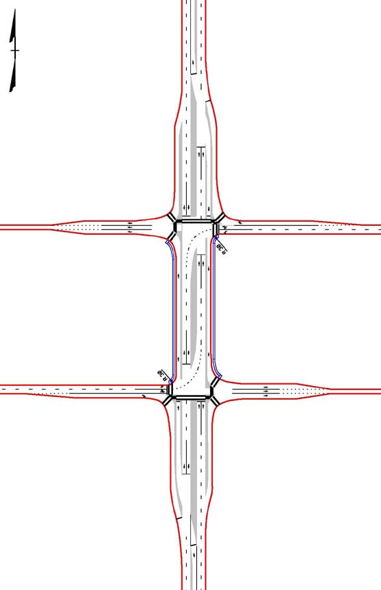
Figure 184. Illustration. Plan view of a DLT interchange.
At the first signalized ramp terminal in the interchange (shown as an oval in figure 185, representing the signal-controlled main intersection), the relocated left-turn movement proceeds straight through the signal-controlled intersection and turns left at the second ramp terminal intersection. Unlike the DCD interchange where both the left and the through movements travel in the flipped direction, only the left-turning traffic travels on the opposite (i.e., flipped direction) side of the road at a DLT interchange. In this figure, the red circle on the right represents the signal-controlled crossover, the orange arrows represent vehicular movements, and the yellow arrow shows the opposing through movement at the signal-controlled crossover.
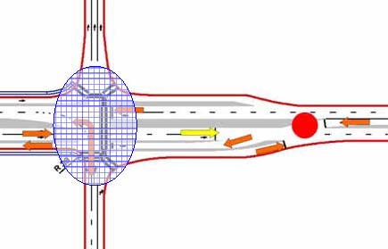
Figure 185. Illustration. Detailed view of movements and paths for half
of the DLT interchange.
Figure 186 shows the typical movements in a DLT interchange configuration. The complete interchange has four signalized junctions, with two at the crossovers for the DLT movements and two at the ramp terminals of the interchange. All four signalized junctions are operated in a coordinated system to ensure the smooth progression of traffic on the crossroad. Because the left-turn movement is relocated between the opposing through and right-turn movements, the signalized nodes of the interchange operate under two-phase signal control.
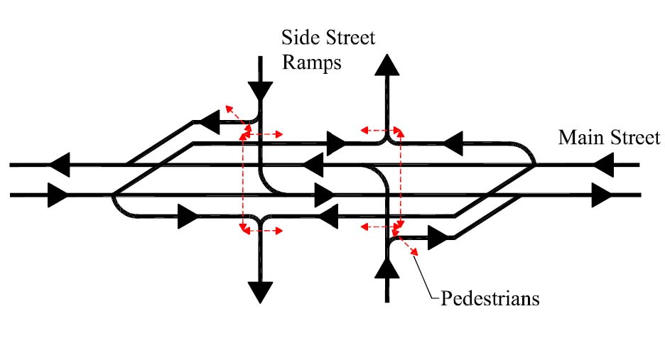
Figure 186. Illustration. Conceptual depiction of the traffic and pedestrian movements at a DLT interchange.
The conversion of a conventional diamond interchange to a DLT interchange has several potential benefits. Introducing the left-turn crossovers reduces the number of phases at the signal-controlled ramp terminals within the interchange. This could reduce delays to drivers, pedestrians, and bicyclists.
A DLT interchange has several disadvantages. Construction of left-turn crossovers and DLTs on the bridge structure for interchanges where the crossroad passes over the mainline freeway likely requires a wider bridge deck and is more expensive compared to a conventional diamond interchange. The design is also counterintuitive to unfamiliar users and therefore could necessitate more extensive signing and marking guidance. In addition, a DLT interchange needs four signalized intersections compared to a conventional diamond interchange where only two signal-controlled intersections are needed.
8.2 GEOMETRIC DESIGN CONSIDERATIONS
As with a DLT intersection, the differentiating design element of a DLT interchange is the left-turn crossover. The DLT lanes typically cross the opposing through traffic at locations that are approximately 400 to 500 ft upstream of the signal-controlled ramp terminals. Appropriate radii that reflect design criteria used at DLT intersections are shown in figure 187. To better communicate the appearance of the approach to a DLT interchange, figure 188 is presented to depict the view of a left-turn crossover at a DLT intersection. This perspective is from a three-dimensional simulation produced for FHWA. While technically the view is of a DLT intersection, it is similar to a perspective view of the approach to a DLT interchange.
Geometrically, the left-turn crossover in a DLT interchange is similar to the design of a left-turn crossover for a DLT intersection. Research into the operation of DLT intersections sponsored by the MDSHA revealed that distance between the crossover and the main intersection was dependent on queuing from the main intersection and on costs involved in constructing a left-turn storage area.(4) Radii of the crossover movements range from 150 to 200 ft. The radii of the left-turn movement at the nodes of the interchange are dependent on the turning movement of a design vehicle.(87)
Median width affects the interchange footprint and consequently the right-of-way acquisition. Designers can obtain minimum median widths from the AASHTO Green Book.(7) Offset recommendations for post-mounted signs should be accounted for in accordance with MUTCD when determining median width.(8) The minimum median width for any type of intersection or interchange is 4 ft.
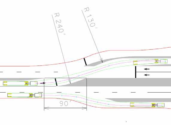
Figure 187. Illustration. Left-turn crossover movement in a DLT interchange.
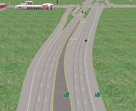
Figure 188. Illustration. Left-turn crossover movement view, as shown in a DLT intersection driver simulator.
In the case of a DLT interchange, a wide median is counterproductive for the following reasons:
- Wide medians result in long walking distances for pedestrians at the interchange. In turn, this results in the need for long pedestrian clearance intervals and potentially increased cycle lengths, which is counterproductive to traffic efficiency.
- Wide medians necessitate a wide interchange footprint and consequently higher bridge deck construction costs.
As discussed in chapter 7, there is concern that this requires a wider median for better separation of the movements. The use of glare screens has been investigated in the Missouri design of DCD interchange and could also prove to be an effective measure for the DLT interchange.(83)
Many considerations can be obtained in the AASHTO Green Book, for example, bridge deck lateral clearance decisions.(7) In addition, typical geometric considerations like interchange spacing, the choice of using an overpass or underpass, sight distance, design speed, horizontal and vertical alignment, superelevation, skew angle, lane widths, shoulder widths, and turning radii can also be found and applied as appropriate. Typical design standards for ramp terminals at on- and off-ramps including ramp location, minimum acceleration, and deceleration lengths can be obtained from the AASHTO publication as well. It also addresses typical standards for median islands, including their installation and use to separate right- and left-turn movements.
Sight distance issues at DLT interchanges are similar to those of conventional diamond interchanges. Typically, there are greater sight distance restrictions on the left-turning vehicles coming from the off-ramps when the side road crosses under the main road. As mentioned previously in the report, the direction of movement at crossovers is counterintuitive to unfamiliar drivers. Proper "Wrong Way" and "Do Not Enter" signing and pavement markings provide mitigation. Signal and lighting equipment on islands at the crossover area should be installed so as not to block drivers' views of the opposing traffic. As in a DCD interchange, the skew angle between the intersecting roadways is important when considering sight distance.
The U-turn movement is restricted in a DLT interchange design because there are turn restrictions at the crossovers and the main intersection. However, as mentioned previously, alternative strategies can be investigated including facilitating U-turn movements upstream of the bridge structure with the help of a median opening.
8.3 ACCESS MANAGEMENT CONSIDERATIONS
Because there have been no DLT interchanges constructed, discussion of access management is based on theoretical considerations rather than empirical experience. The NCHRP Report 420 discusses the design, location, and spacing of driveways; access separation techniques at interchanges; and principles that can be applied to DLT interchanges.(12) Chapter 9 of the NCHRP Report 420 discusses in detail the access separation techniques at interchanges. In addition, many States have adopted access management policies for rural and urban areas, and these policies could be applied to a DLT interchange as appropriate.
Access to adjacent properties is limited by this design, and each driveway needs to be considered individually. Driveways should be located outside of the crossover signal-controlled intersection. Turns to and from nearby driveways may need to be limited to right-in and right-out depending on the proximity to the interchange and crossovers. As with the DLT intersection, the U-turn movement is prohibited at the main intersection. Alternative strategies for placement of U-turn movements are mentioned in the last section of this chapter. Chapters 2 and 7 of this report have similar U-turn considerations and contain applicable discussion as well.
As with the DCD interchange, the use of frontage roads in a DLT interchange complicates the design and traffic operations of the interchange. Presence of frontage roads adds one or more additional signal phases; therefore, the frontage roads reduce some of the benefit gained with the DLT interchange design.
8.4 TRAFFIC SIGNALIZATION TREATMENTS
A DLT interchange typically has four signalized junctions or nodes. Traffic signal control is needed at the crossovers and the ramp terminal, as shown in figure 189. The signal control at each of the four junctions operates with two phases for the alternative opposing movements, but the four signal-controlled junctions need to be coordinated to maintain progression on the side street arterial. In figure 189, the green ovals represent typical signal locations.
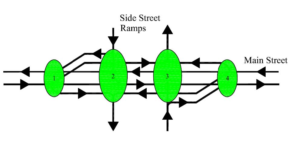
Figure 189. Illustration. Typical DLT interchange signal locations.
8.4.1 Signal Design
As with conventional intersections and DLT intersections, traffic signal control at a DLT interchange may be fully actuated to minimize delay. Detectors in all lanes approaching the crossovers and in the lanes approaching the signal-controlled ramp terminals can be used. The durations of signal phases can vary on a cycle-by-cycle basis. A permissible signal phasing scheme for a DLT interchange operating under one signal controller is shown in figure 190. The possible locations of loop detectors for a DLT interchange are shown in figure 191.
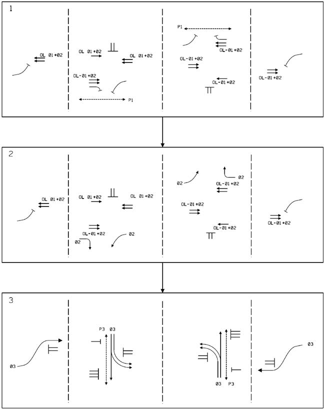
Figure 190. Illustration. Signal phasing for a DLT interchange operating under a single controller.
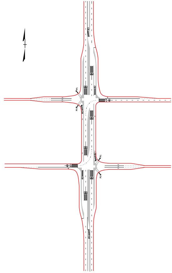
Figure 191. Illustration. Detector locations for a DLT interchange for signal phasing.
One possible signal pole and mast arm layout is shown in figure 192. These locations are similar to a DLT intersection except at two ramp terminals. Since the ramps carry one-way traffic, signal heads are needed for three approaches at the ramp terminals. At a DLT intersection, there is a need for signal heads serving all approaches. Angular left-turn arrows signal displays that can be used in signal heads at the left-turn crossovers.
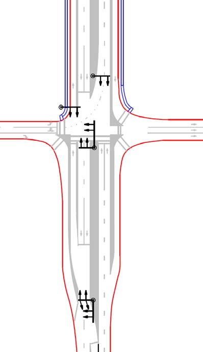
Figure 192. Illustration. Possible signal pole and mast arm locations for a DLT interchange.
8.4.2 Signing and Marking
Signing and marking a DLT interchange entails significant differences from a conventional interchange, especially at the midblock left-turn crossovers and the turning restrictions at the main interchange. As mentioned for the DCD interchange design in the previous chapter, the key features of the signing and marking include the following:
- Use of overhead signing to clearly communicate lane use and directions.
- Use of advance signing and guide sign applications on the exit ramps and on the bridge structure.
- Use of skip marks on the left-turn lanes for clear guidance through the intersection crossover area.
- Use of "Wrong Way" and "Do Not Enter" signs for protection against wrong maneuvers at the left-turn crossovers and the bridge deck structure.
- Use of wrong-way pavement arrows on the through lanes at the crossovers.
In addition, other measures that have been investigated for other alternative intersections and interchanges like the use of glare screens and alternate "Keep Left" signs should be considered.
8.5 ACCOMMODATION OF PEDESTRIANS, BICYCLISTS, AND TRANSIT USERS
Pedestrian accommodation in a DLT interchange involves crossing locations and signalization at the ramp terminal intersection of the interchange. These intersections are similar to a partial DLT intersection with the left-turn crossover side street.
Since there were no existing implementations of DLT interchanges at the time of this report, the existing example of pedestrian implementation at DLT intersection locations referenced in chapters 3 and 7 can be used as starting points for design purposes. These two chapters discuss pedestrian accommodation, including accessibility, in detail. The discussion is also applicable to the DLT interchange, including potential safety measures applicable to the left-turn crossovers in a DLT interchange.
Figure 185 showed crosswalk locations, and figure 186 schematically showed where pedestrian crosswalks may be located at a typical DLT interchange. Figure 193 shows the typical pedestrian movements at a DLT interchange. The direction of DLT vehicles on the crossroad between ramp terminal intersections should not pose a problem to pedestrian movements. Sidewalks should be installed on the roadway depending on locations of pedestrian generators, pedestrian movements, and the future pedestrian needs of the interchange. If right-of-way, access management, or other challenges exist, sidewalks may need to be relocated to nearby intersections along the side street arterial.
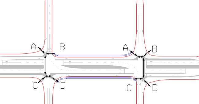
Figure 193. Illustration. Pedestrian movements in a DLT interchange.
Bicyclists operating along the side street through a DLT interchange can be accommodated with the use of bicycle paths or shared-use paths, and the above pedestrian accommodation discussion applies to bicycle traffic. As with SPUIs, pedestrians and bicyclists can also be accommodated with the help of a shared-use overpass.
In the case of a DLT interchange, the location of bus stops is dictated by the location of the left-turn crossovers on the side street arterial and the pedestrian generators. If location of the pedestrian generators dictates near-side bus stop, then the bus stops would be located upstream of the crossover and right-turn bays. Similarly, far-side bus stops would be located downstream of the crossover, as shown in figure 194. Further guidance on bus stop location, design type (curbside, bus bay, etc.), and ADA accessibility guidelines can be obtained from existing literature including Transit Cooperative Research Program (TCRP) Report 19.(89)
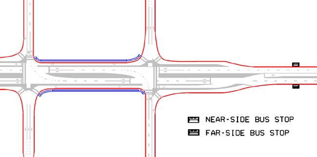
Figure 194. Illustration. Transit stop locations in a DLT interchange.
8.6 OPERATIONAL PERFORMANCE
VISSIM® was used to gain insight into the operational performance of the DLT interchange in comparison to the TD interchange. Two geometric design cases of DLT interchanges and two geometric design cases of TD interchanges were simulated. Table 33 shows the geometric design configurations of the cases simulated. The lane configurations and geometric features for the DLT interchanges and the corresponding TD interchanges were similar. The vehicular volumes on opposing approaches were balanced (50:50 directional split). The VISSIM® simulation network was 1 mi long on the major and minor road approaches for the cases simulated. A discussion of the simulation results for all of the geometric design cases is provided below.
The following assumptions were employed in the VISSIM® model for each simulated scenario:
- Optimum fixed signal timing determined using Synchro®.(21)
- Yellow times determined using ITE policy.
- All-red times determined using ITE policy.
- A total of 5 percent heavy vehicles on all legs.
- A total of 350-ft left-turn bay lengths upstream of the displaced crossover junction.
- A total of 325-ft left-turn bay lengths downstream of the displaced crossover junction.
- A 0.5-mi network size in each direction from the main intersection.
- Single right-turn bays on the major road.
- Right turn on red allowed at each signal, no left turn on red allowed.
- A signal at each DLT crossover.
- A 10-ft median width on bridge deck.
- A 45 mi/h desired speed on major road.
- A 25 mi/h desired speed on off-ramp.
- Saturation headway of approximately 1,900 veh/h/lane (alpha = 3 and beta = 2).
- Seeding time of 30 minutes for the simulations.
- Running period of 60 minutes for the simulations.
Based on the VISSIM® simulation results, DLT interchanges with six lanes on the bridge processed approximately 6,200 veh/h, while an equivalent TD interchange processed 4,200 veh/h. Similarly, DLT interchanges with 10 lanes on the bridge processed approximately 8,600 veh/h, while an equivalent TD interchange processed 6,800 veh/h.
Thus, DLT interchanges provided 20 to 45 percent additional throughput on the bridge deck
for the same number of lanes when the through flows were balanced. However, it is important
to note that DLT interchanges typically performed better than TD interchanges when the on-ramp left-turn volumes were moderate, the major road through volumes were high, and the off-ramp volumes were moderate. The DLT interchange was best suited to conditions where the bridge deck width was limited, but right-of-way was available upstream and downstream of the bridge structure. Several guidelines were derived based on the VISSIM® simulation results. For balanced traffic flows, the maximum capacity of the DLT interchange through and left-turn lanes on the bridge were 800–850 veh/h/lane and 350 veh/h/lane, respectively. For these mainline volumes, the maximum entering capacity was 400 veh/h/lane entering the crossroad from the ramps.
Table 33. Service volumes and delays for TD and DLT interchange designs.
Geometric Cases |
Input Volumes |
Simulation Thruput |
Average Delay (s/veh) |
Major Road |
Ramp |
Total Input |
Major Road |
Ramp |
Total Thruput |
Left |
Thru |
Right |
Left |
Right |
Left |
Thru |
Right |
Left |
Right |
1 |
DLT interchange |
Two thru lanes, one left lane, one right lane per approach on major road, two thru lanes, one left lane per approach on bridge, two left, and one right on each off-ramp |
250 |
1,600 |
300 |
350 |
300 |
5,600 |
250 |
1,601 |
301 |
355 |
271 |
5,554 |
34.4 |
300 |
1,800 |
300 |
600 |
300 |
6,600 |
275 |
1,635 |
271 |
620 |
309 |
6,218 |
80.7 |
350 |
1,600 |
300 |
650 |
300 |
6,400 |
333 |
1,574 |
292 |
650 |
273 |
6,243 |
87.8 |
600 |
600 |
300 |
400 |
250 |
4,300 |
401 |
404 |
199 |
408 |
229 |
3,279 |
112.3 |
600 |
300 |
300 |
400 |
250 |
3,700 |
395 |
249 |
205 |
407 |
225 |
2,859 |
126.4 |
300 |
600 |
300 |
400 |
250 |
3,700 |
301 |
591 |
313 |
405 |
230 |
3,679 |
33.6 |
2 |
DLT interchange |
Three thru lanes, two left lanes, one right lane per approach on major road, three thru lanes, two left lanes per approach on bridge, two left lanes, and one right lane on each off-ramp |
550 |
2,500 |
350 |
400 |
250 |
8,100 |
521 |
2,465 |
343 |
402 |
233 |
7,924 |
44.3 |
550 |
2,500 |
350 |
800 |
250 |
8,900 |
524 |
2,484 |
344 |
740 |
207 |
8,596 |
70.7 |
900 |
1,000 |
300 |
500 |
250 |
5,900 |
742 |
923 |
278 |
505 |
243 |
5,378 |
113.8 |
900 |
500 |
300 |
500 |
250 |
4,900 |
743 |
458 |
278 |
507 |
247 |
4,462 |
113.8 |
450 |
1,000 |
300 |
500 |
250 |
5,000 |
428 |
998 |
299 |
509 |
240 |
4,946 |
35.2 |
3 |
TD interchange |
Two thru lanes, one left lane, one right lane per approach on major road, two thru lanes, one left lane per approach on bridge, two left, and one right on each off-ramp |
600 |
600 |
300 |
400 |
250 |
4,300 |
546 |
576 |
283 |
407 |
256 |
4,133 |
99.3 |
600 |
300 |
300 |
400 |
250 |
3,700 |
552 |
272 |
280 |
413 |
256 |
3,545 |
109.5 |
300 |
600 |
300 |
400 |
250 |
3,700 |
288 |
598 |
301 |
412 |
256 |
3,709 |
37.4 |
4 |
TD interchange |
Three thru lanes, two left lanes, one right lane per approach on major road, three thru lanes, two left lanes per approach on bridge, two left lanes, and one right lane on each off-ramp |
550 |
2,500 |
350 |
800 |
250 |
8,900 |
429 |
1,985 |
274 |
454 |
257 |
6,797 |
141.9 |
900 |
1,000 |
300 |
500 |
250 |
5,900 |
895 |
1,010 |
298 |
512 |
257 |
5,940 |
52.0 |
900 |
500 |
300 |
500 |
250 |
4,900 |
893 |
500 |
290 |
509 |
257 |
4,898 |
58.8 |
450 |
1,000 |
300 |
500 |
250 |
5,000 |
449 |
996 |
296 |
513 |
257 |
5,021 |
38.8 |
8.7 SAFETY PERFORMANCE
It is not possible to present any empirical data on the crash experience at DLT interchanges, as there are no existing installations. One can speculate on the future safety performance of this type of alternative interchange. It may be that the separation of basic conflict areas and the reduction of conflict points positively affect safety. Using a conceptual approach, it can be shown that a conventional diamond interchange has two major conflict areas with a total of 26 conflict points. At a DLT interchange, there are 16 conflict points that occur within 4 conflict areas. The four conflict areas are the four signal-controlled intersections. Figure 195 presents a conceptual diagram that identifies the 16 conflict points at a DLT interchange. (The two additional conflict points would be created if the diverge point for the left turn from the main line was spatially separated from the diverge point for the right turn from the main line.) In comparison, as was shown in figure 181, a conventional diamond interchange has 26 conflict points, but they are concentrated in 2 conflict areas. Until a DLT interchange is constructed and crash data become available, it remains to be seen whether spreading the conflict points over four areas produces better safety performance than concentrating them in two areas.
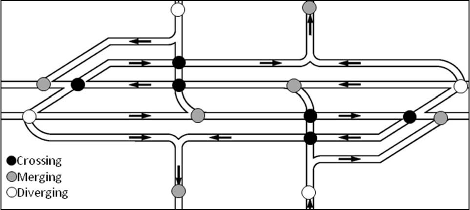
Figure 195. Illustration. Conflict points in a DLT interchange.
The counterintuitive features of the DLT interchange, especially the presence of left-turn crossovers and left-turn movement on the opposite side of the crossroad between ramp terminal intersections, raise questions about safety performance, especially for unfamiliar drivers. Signing and pavement markings as well as public information and education campaigns could be used to reduce the potential for crashes involving unfamiliar drivers.
8.8 CONSTRUCTION COSTS
Since there are no existing installations of a DLT interchange at the time of this report, no data on actual construction costs are available. The presence of left-turn crossovers at the approaches of the side street arterial would result in a wider footprint, which is depicted in figure 196.
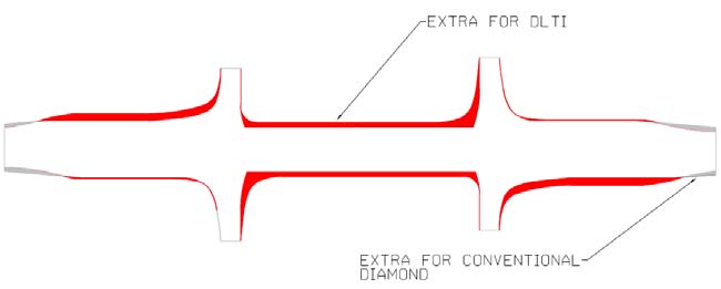
Figure 196. Illustration. Footprint comparison of a DLT interchange versus a conventional diamond interchange.
The wider footprint produces higher right-of-way acquisition costs compared to that of a conventional diamond interchange. This also increases the amount of earthwork and paving construction costs. Items like mobilization, overhead lighting, pavement markings, and drainage costs are not significantly different between the DLT interchange and a conventional diamond interchange. When comparing signal equipment between a DLT interchange and a conventional diamond interchange, four signal mast arms are present at the main intersection similar to a conventional intersection. Additionally, single mast arms are provided at each left-turn crossover. Therefore, for a DLT interchange, the signal equipment is estimated to cost twice as much. The additional signing needed to guide drivers through the interchange would increase the signing-related costs over what are expected for a conventional interchange. Consequently, it is expected that construction costs would generally be higher for a DLT interchange than a comparable conventional interchange.
8.9 SEQUENCING OF CONSTRUCTION
Maintenance of traffic during construction of a DLT interchange is typically an issue of converting an existing conventional diamond interchange into a DLT interchange. Since a DLT interchange is considered to be an amalgamation of a diamond interchange and a DLT intersection, techniques illustrated previously should be referenced in addition to existing literature for conventional and SPUIs.
8.10 OTHER CONSIDERATIONS
There are additional issues to consider when determining whether a DLT interchange is appropriate for a specific situation including enforcement and emergency vehicle needs, lighting, public information, and education. Enforcement needs and emergency vehicle access issues at a DLT interchange are similar to issues documented for a DLT intersection in chapter 2. Similarly, the potential for crossover blockage during traffic incidents or power outages dictate that mitigation options (such as a bypass shoulder and generator) be considered.
Adequate highway lighting should be provided at the ramp junctions and the bridge structure. Important design principles like uniformity of light and minimization of glare should be followed. Since the interchange has counterintuitive movements, overhead lighting would be beneficial for unfamiliar drivers using the interchange area during nighttime and inclement weather conditions. Existing lighting standards and specifications outlined in AASHTO's Roadway Lighting Design Guide, FHWA's Roadway Lighting Handbook, and the IESNA publications including Recommended Practices for Roadway Lighting, Recommended Practices for Tunnel Lighting, and Recommended Practices for Sign Lighting could be used for optimal lighting in a DCD interchange. (See references 26–30.) NCHRP Synthesis 345 provides guidelines for roadway lighting for SPUIs.(85)
As with the DLT intersection and DCD interchange designs, a public information and education campaign are important for the safe and efficient use of the interchange and the public acceptance of the design. Distributing information through various media outlets would be important prior to the opening of the intersection as well as monitoring driver behavior after its opening to determine the need for additional education and possible enforcement efforts.
8.11 APPLICABILITY
As with all the designs described in this report, the DLT interchange design is applicable under certain conditions. A primary reason to choose the DLT interchange instead of a conventional diamond interchange is the two-phase signal operation resulting in the ability to process higher volumes approaching the bridge deck. DLT interchanges are best suited when left-turn volumes from the arterial to the on-ramp are moderate to heavy, the major road through volumes are heavy, and the volumes from the off-ramp from the freeway are moderate. Moreover, DLT interchanges provide higher throughput than a conventional diamond when the major through volumes are balanced.
Some of the situations where a DLT interchange may be suitable are as follows:
- Heavy and balanced through volumes on the major (or arterial) road.
- Moderate to heavy left-turn volumes from the major road.
- Low to moderate left-turn volumes from ramps.
- Limited bridge deck width with right-of-way available on approaches.
8.12 SUMMARY
At the time of this report, there were no existing DLT interchange installations. Theoretically, the DLT interchange offers the following benefits compared to conventional interchange forms:
- More efficient simplified two-phase operation.
- Increased capacity.
- Reduced delay.
- Reduced cost.
- Separated conflict points.
Agencies considering DLT interchanges should also be aware of disadvantages of the design relative to conventional interchanges as described earlier in the chapter. Specifically, additional right-of-way prior to the bridge structure may make this design infeasible.
|


