U.S. Department of Transportation
Federal Highway Administration
1200 New Jersey Avenue, SE
Washington, DC 20590
202-366-4000
Federal Highway Administration Research and Technology
Coordinating, Developing, and Delivering Highway Transportation Innovations
 |
| This report is an archived publication and may contain dated technical, contact, and link information |
|
Publication Number: FHWA-HRT-09-060
Date: April 2010 |
||||||||||||||||||||||||||||||||||||||||||||||||||||||||||||||||||||||||||||||||||||||||||||||||||||||||||||||||||||||||||||||||||||||||||||||||||||||||||||||||||||||||||||||||||||||||||||||||||||||||||||||||||||||||||||||||||||||||||||||||||||||||||||||||||||||||||||||||||||||||||||||||||||||||||||||||||||||||||||||||||||||||||||||||||||||||||||||||||||||||||||||||||||||||||||||||||||||||||||||||||||||||||||||||||||||||||||||||||||||||||||||||||||||||||||||||||||||||||||||||||||||||||||||||||||||||||||||||||||||||||||||||||||||||||||||||||||||||||||||||||||||||||||||||||||||||||||||||||||||||||||||||||||||||||||||||||||||||||||||||||||||||||||||||||||||||||
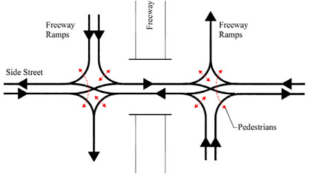
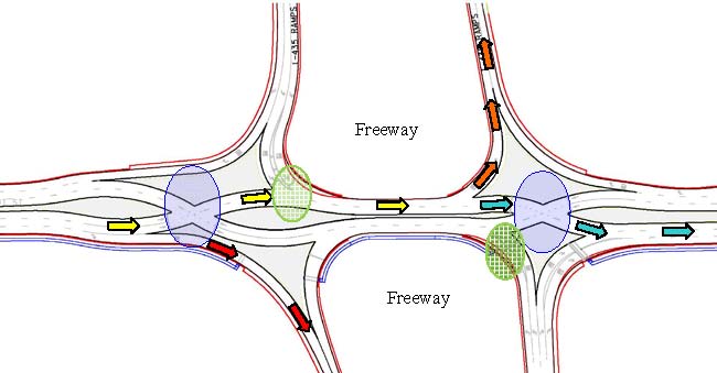
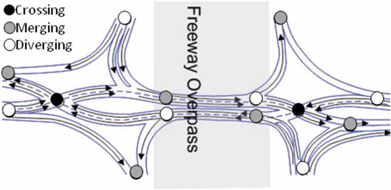
Alternative Intersections/Interchanges: Informational Report (AIIR)CHAPTER 7. DOUBLE CROSSOVER DIAMOND INTERCHANGE7.1 INTRODUCTIONThe DCD interchange is a new interchange design that is slowly gaining recognition as a viable interchange form that can improve traffic flow and reduce congestion. Similar to the design of a conventional diamond interchange, the DCD interchange differs in the way that the left and through movements navigate between the ramp terminals. The purpose of this interchange design is to accommodate left-turning movements onto arterials and limited-access highways while eliminating the need for a left-turn bay and signal phase at the signalized ramp terminals. Figure 153 shows the typical movements that are accommodated in a DCD interchange. The highway is connected to the arterial cross street by two on-ramps and two off-ramps in a manner similar to a conventional diamond interchange. However, on the cross street, the traffic moves to the left side of the roadway between the ramp terminals. This allows the vehicles on the cross street that need to turn left onto the ramps to continue to the on-ramps without conflicting with the opposing through traffic. There is no patent on the DCD interchange design as there are with some of the other designs discussed in this report. Figure 153. Illustration. Typical DCD interchange configuration. As in a conventional diamond interchange, the right-turn movements from the cross street to the ramps occur at the ramp terminal intersections. Using figure 154, which shows a situation where the freeway mainline passes under the crossroad, the through and left-turn movements (depicted as yellow arrows) are criss-crossed so that the eastbound traffic travels on the roadway that is to the left, and the westbound traffic travels on the roadway to the right in the interchange area. The intersections where the opposite directions of travel cross are under signal control. Across the bridge, vehicles travel on the opposite side of the road than is normal. After crossing the bridge, the left-turn movements proceed to the ramps of the major street without any further signal control (depicted as orange arrows). The opposing right-turn movements merge with the left-turning traffic on the ramp. The through movements on the crossroad cross over to the right side at the second signal intersection and continue in their respective directions (shown as blue arrows). In addition, the red arrows depict side street right-turn movement while the blue circles show the signal-controlled crossovers. Under this configuration, the two crossovers operate under signal control with two phases. Figure 154. Illustration. Crossover movement in a DCD interchange. 7.1.1 Existing DCD InterchangeAs of this report, there are four known existing applications of DCD interchanges. The first one in the United States opened to traffic on June 22, 2009, in Springfield, MO. Three additional DCD interchanges have existed in France for more than two decades. The four known locations include the following:
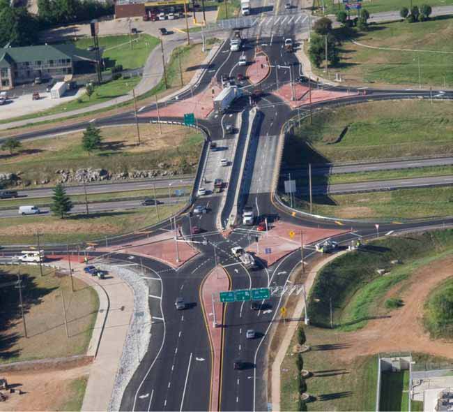
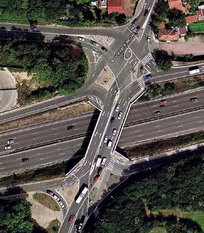
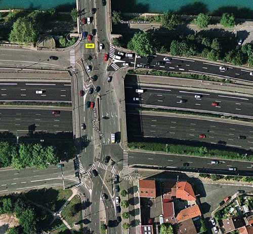
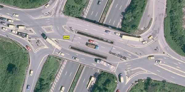
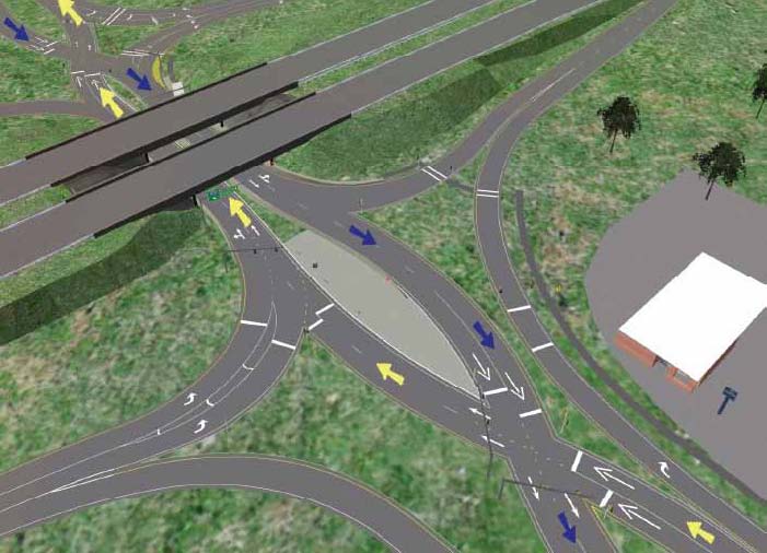
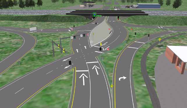
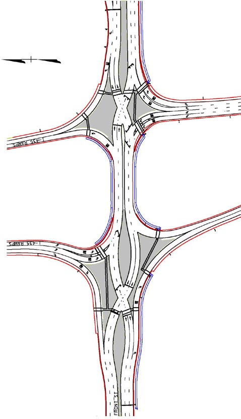
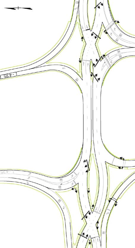
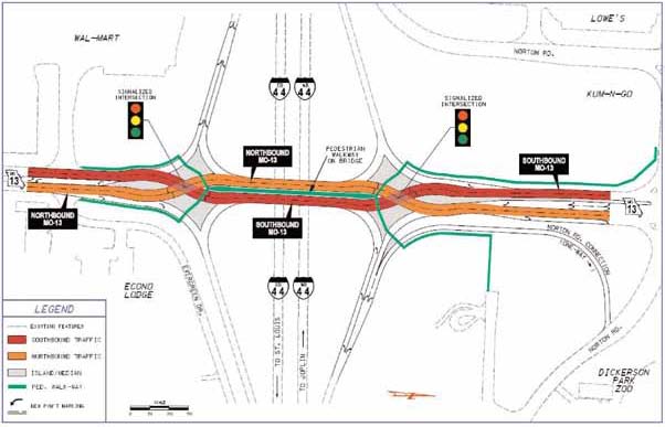
Figure 155. Photo. First U.S. DCD interchange in Springfield, MO. Figure 156. Photo. DCD interchange in Versailles, France. Figure 157. Photo. DCD interchange in Perreux-sur-Marne, France. Figure 158. Photo. DCD interchange in Seclin, France. The DCD interchange in Springfield, MO, was constructed to replace an existing conventional diamond interchange and is in use.(79) Several additional DCD interchanges are under construction and being planned in Missouri. A DCD interchange was developed for the existing conventional diamond interchange at the intersection of I-435 and East Front Street in Kansas City, MO. Construction is expected to begin in 2010.(80) The aerial perspective views of the simulated version of this planned project are shown in figure 159 and figure 160. A second DCD interchange under construction in Missouri is at the existing diamond interchange at the crossing of I-270 and Dorsett Road in Maryland Heights. According to the Missouri Department of Transportation (MoDOT) Web site, construction will be completed by November 2011.(81) A third DCD interchange site under construction is located at the crossing of U.S. Route 60 and National Avenue in Springfield, MO. The DCD interchange is also one of the two alternatives being considered for the interchange of I-590 and Winton Road in Brighton, NY. The construction is anticipated to start in winter 2010.(82) In addition, several agencies in Oregon, Maryland, and New Mexico are considering DCD interchange options as part of project planning studies for interchange design and modification. Figure 159. Illustration. Simulated DCD interchange.
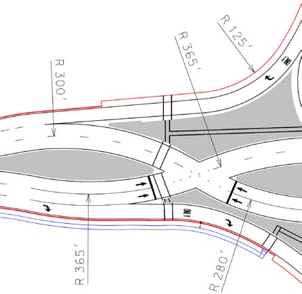
Figure 160. Illustration. Crossover of a simulated DCD interchange. 7.1.2 Advantages and Disadvantages of DCD InterchangesA DCD interchange is expected to be beneficial in situations where high left-turn and through volumes contribute to high delays. The DCD interchange design enables the signal phases to be reduced by allowing movements from the ramps to proceed concurrently with the through movements on the crossroad. As a result, the signal-controlled crossovers operate with two-phase signal control compared to a conventional diamond interchange which normally has three-phase signal control. A DCD interchange has fewer conflict points compared to an equivalent diamond interchange, which can lead to fewer crashes.(76) Another benefit of the DCD interchange is that it combines lane assignments for the left-turn and through movements on the bridge structure and therefore requires a narrower bridge structure compared to a conventional diamond interchange. A possible drawback of the DCD interchange is driver confusion that may result from the counterintuitive direction of travel between the ramp terminals of the interchange. Driver confusion can be reduced with the help of proper designing, signing, and marking.(83) In addition, glare screens can be used, as discussed later in the chapter, to effectively reduce driver confusion. Pedestrian accommodations for a DCD interchange include crossings and signalization at the ramp junctions or nodes of the interchange. Crossing the arterial crossroad is slightly different from crossing at a conventional diamond interchange. Because the crossover junctions in a DCD interchange operate with two-phase signal control, pedestrians cross the junction in two stages. A central island serves as refuge for pedestrians between each stage or signal phase. 7.2 GEOMETRIC DESIGN CONSIDERATIONSFigure 161 shows a design for a DCD interchange. As of this report, MoDOT is in the planning stage with this DCD interchange. The primary design element of a DCD interchange is the relocation of the left-turn and through movements to the opposite side of the road within the bridge structure. The turning radii used at the crossover junction to displace these movements is around 300 ft. Consideration should be given to designing radii at crossovers with heavy vehicles in mind. On rural locations where the minor street has high-speed limits, the use of reverse curvature has been suggested. This may result in loon-like flare-outs at the ends of the bridge structure, as shown in figure 162.(79) Additional right-of-way may be required to widen the bridge or the underpass structure.
Figure 161. Illustration. Typical full DCD interchange plan view.
Figure 162. Illustration. Crossover movement in a DCD interchange. Median width is also an important design element for a DCD interchange. Greater median width is required for the flaring needed for reverse curves. Designers can obtain minimum median widths from the AASHTO Green Book.(7) Designers should also take into account the installation of post-mounted signs on medians on the bridge deck for safe and effective channelization of traffic. Appropriate offsets for signs should be in accordance with the MUTCD.(8) Recent driver simulator experiments on the DCD interchange, which included the use of glare screens, showed no erroneous maneuvers by tested subject drivers.(8) MoDOT performed extensive analysis on the benefits of the DCD interchange alternative compared to a tight urban diamond interchange (TUDI).(84) Some of the conclusions from comparing the two alternatives for this location are as follows:
Some suggested design practices, based on MoDOT input, include the following:
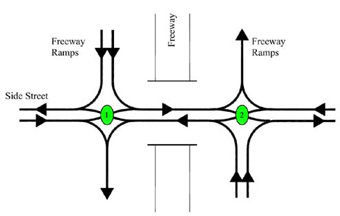
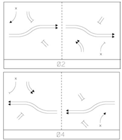
7.3 ACCESS MANAGEMENT CONSIDERATIONSEffects on adjacent businesses and land users should be reviewed closely on a case-by-case basis, particularly if driveway locations affect signal operation and number of phases. Any driveways should be located beyond the crossover signal-controlled intersection. Many transportation department agencies adhere to minimum spacing policies with respect to the distance from interchange ramps to median openings and signal-controlled intersections. Those same policies are equally applicable to DCD interchanges. Little consideration has been given to frontage roads as part of DCD interchanges, as it would be more complicated to add them to a DCD interchange than to conventional diamond and single-point urban interchanges. Since the main operational benefit of the DCD interchange is the efficient two-phase control, the inclusion of frontage roads would incorporate additional phasing, thus reducing the benefit of the configuration. Frontage roads are used to enhance local access, and their application usually depends on traffic and land-use needs. In addition, frontage roads can be integrated with interchanges to alleviate congestion on arterials. Chapter 10 of the NCHRP Report 420 discusses application guidelines for one-way and two-way frontage roads and their key features.(12) U-turn movements are penalized in a DCD interchange design because the crossover requires turn restrictions. However, U-turn movements can be facilitated upstream of the interchange with the help of a median opening as described in chapter 2. Chapter 4 of the NCHRP Report 420 discusses design, location, and spacing of driveways in detail.(12) Chapter 9 of the NCHRP Report 420 discusses the access separation techniques at interchanges and access separation policies for several State agencies in rural and urban areas, which can be applied to a DCD interchange.(12) 7.4 TRAFFIC SIGNALIZATION TREATMENTSA DCD interchange typically has two signalized junctions or nodes for left-turn crossovers, which are shown in figure 163. These junctions are two-phase signals, with each phase dedicated for the alternative opposing movements. Compared to conventional interchanges, the DCD interchange allows for relatively shorter cycle lengths at the signalized junctions, which reduce the lost time per cycle as a result. Left turns from both off-ramp terminals are preferably operated under signal control because turning angles are very sharp. Moreover, off-ramp right turns are also signalized when no acceleration lanes are provided for merging because right-turning drivers are normally seeking gaps on the right side of the conflicting entry flow and not the left side, as in the DCD geometry. In the figure, the green circles represent typical signal locations. Figure 163. Illustration. Typical DCD interchange signal locations. 7.4.1 Signal Design and OperationsThe DCD interchange design is suitable for interchanges with heavy ramp movements and relatively low through volumes on the arterial or directional unbalanced through volumes on the arterial. Signals on a DCD interchange may be fully actuated to minimize delay. Detectors can be used at all of the crossovers on all approaches, and durations of signal phases can vary on a cycle-by-cycle basis. Both of the signalized junctions can operate under a single controller or each with a separate controller, with phasing schemes similar to those illustrated in figure 164 and figure 165, respectively.
Figure 164. Illustration. Signal phasing for a DCD interchange operating under a single controller.
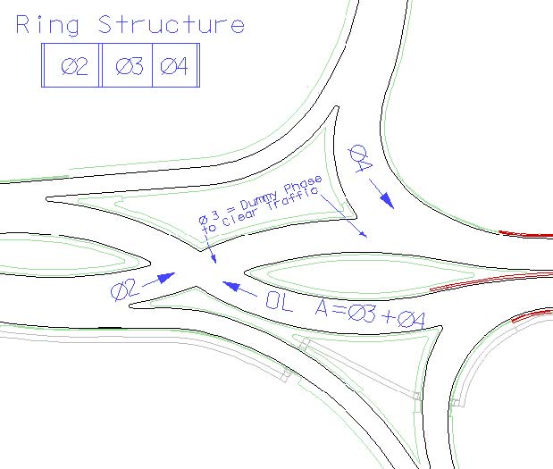
Figure 165. Illustration. Signal phasing for a DCD interchange operating under separate controllers. Signal phasing, as proposed by MoDOT designers for the eastern intersection of the DCD interchange in Kansas City, MO, is shown in figure 166. It should be noted that the geometry of the east crossover junction at the Kansas City DCD interchange allows for the more simplified phasing as illustrated in figure 164 and figure 165. This is because the spacing between the crossover junction and the intersection with the left turns from the off-ramp is very close. However, in the case of the west intersection (or ramp terminal), left turns from the southbound off-ramp merge onto the arterial distance downstream from the crossover intersection. Under the simplified phasing in figure 164 and figure 165, this requires a long clearance interval. It can be seen in figure 166 that MoDOT accommodated this with an overlap phase for the time to clear the intersection.
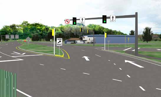
Figure 166. Signal phasing used for proposed DCD interchange at Kansas City, MO.(84) Signal pole and head locations are shown in figure 167 from an aerial plan view. Typical far side mast arm poles are proposed for each signal-controlled approach. Different views of the signal heads from a driver perspective are shown in figure 168 through figure 170. The use of straight green arrows for the signal heads at the crossovers have been proposed for the DCD interchange in Kansas City, MO (see figure 168). Nearside signal heads have also been proposed to provide additional guidance. The FHWA driver simulation study indicated that sight distance to the traffic signal heads was an issue.(83) Pedestrian considerations are discussed in detail in section 7.5. In general, the signalized crossovers with two-phase signal control have short cycle lengths and therefore shorter pedestrian clearances and less exposure than conventional intersections.(84) Similar to conventional intersections, under most scenarios, pedestrians are required to cross channelized turning roadways that carry free-flowing traffic. However, in the Kansas City, MO, DCD interchange, signal-controlled pedestrian crossings were proposed on the two on-ramps (ramps exiting the arterial heading toward the merge onto the freeway). Signal control at these locations is unexpected from a driver perspective and could result in additional rear-end crashes at the ramps.
Figure 167. Illustration. Signal mast arm and pole locations being implemented in Kansas City, MO.
Figure 168. Illustration. Signal pole locations proposed in Kansas City, MO, from the FHWA driver simulator.(83)
Figure 169. Illustration. Signal pole locations proposed for the planned DCD interchange in Kansas City, MO.(83)
Figure 170. Illustration. Green arrows, overhead lane usage, and skip markings proposed for the planned DCD interchange in Kansas City, MO.(83) 7.4.2 Signing and MarkingThe highway signs and pavement markings implemented at a DCD interchange are similar to those implemented at a conventional diamond interchange. The significant differences from a conventional interchange relate to the treatment at the midblock left-turn crossovers and the turning restrictions at the main interchange. Some of the key features of signing and marking a DCD interchange include the following:
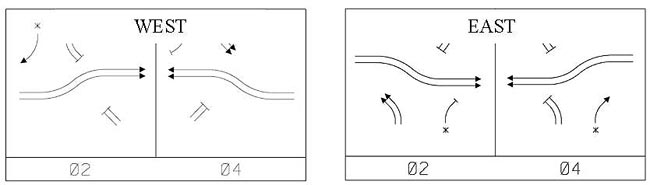
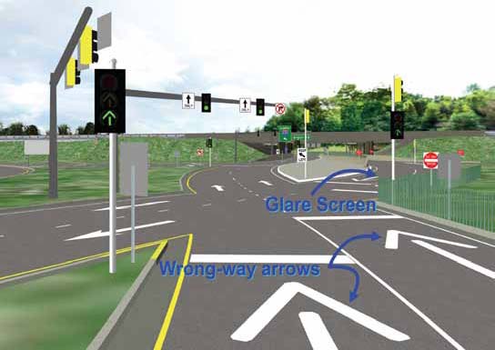
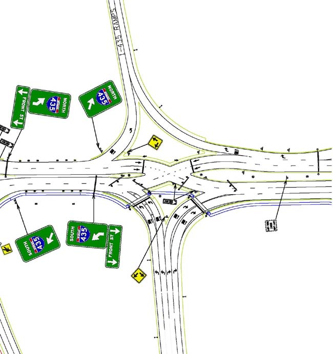
Figure 171. Illustration. "Wrong Way" and "One Way" signs proposed for the DCD interchange in Kansas City, MO.(83) Figure 172 and figure 173 show the signing and marking plan developed by MoDOT for the planned DCD interchange in Kansas City, MO. Figure 174 through figure 176 illustrate some of the signing and marking techniques used from a driver's point-of-view. During the planning stages of the DCD interchange alternative, the following issues were debated:
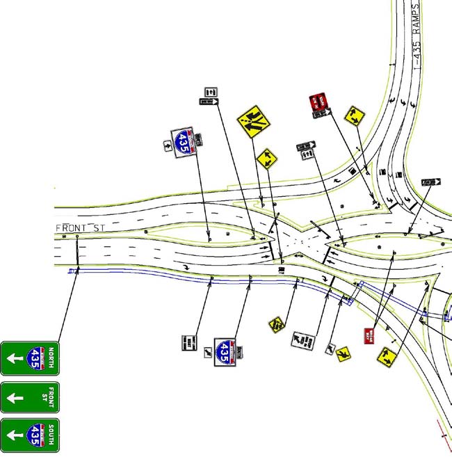
Figure 172. Illustration. DCD interchange signing and marking plan derived from Missouri practice—west end.
Figure 173. Illustration. DCD interchange signing and marking plan derived from Missouri practice—east end.
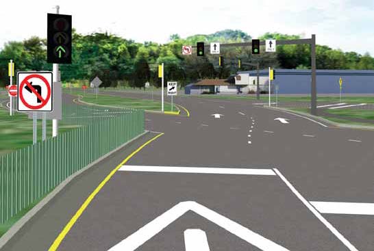
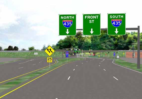
Figure 174. Illustration. Overhead signing proposed for the planned DCD interchange ahead of the crossover in Kansas City, MO.(83)
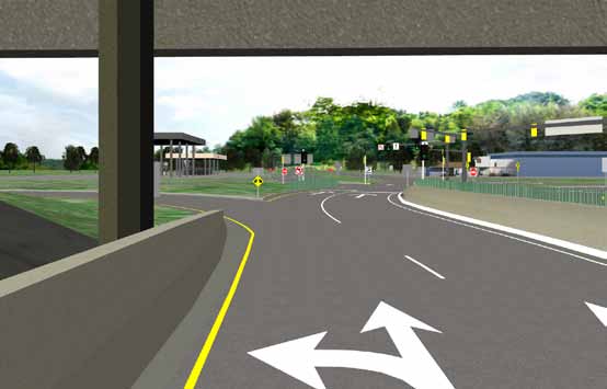
Figure 175. Illustration. Signing and pavement marking proposed for the planned DCD interchange ahead of the left turn off-ramp in Kansas City, MO.(83)
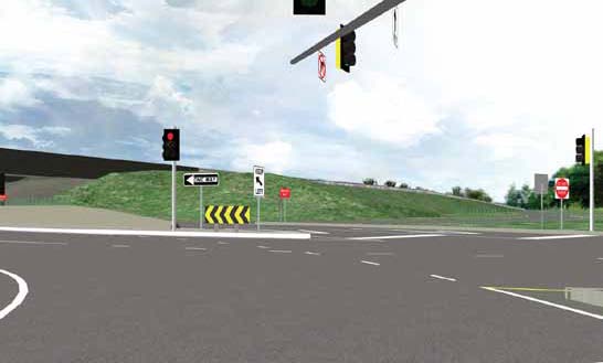
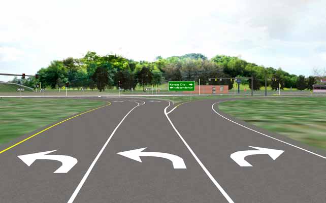
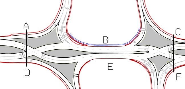
Figure 176. Illustration. Advanced pavement markings and guide signs from the off-ramp.(83) 7.5 ACCOMMODATION OF PEDESTRIANS, BICYCLISTS, AND TRANSIT USERSAs discussed earlier in this chapter, figure 161 shows where pedestrian crosswalks may be located at a DCD interchange. The DCD interchange in Versailles, France, has crosswalks across some of the ramps at the interchange nodes, as can be seen in figure 156. Pedestrian crossings for a DCD interchange involve crosswalks and signalization at the junctions of the interchange. Figure 177 shows the pedestrian movements at a DCD interchange. In this concept, walkways are shown on both the south and north sides of the bridge over the freeway. Depending on the pedestrian network in the vicinity of the interchange, it may not be necessary to have pedestrian walkways on both sides. In MoDOT's design, pedestrians cross only on the south side of Front Street. Since the crossover junctions in a DCD interchange operate on a two-phase signal control, pedestrians are directed to cross the arterial in two stages. Adequate pedestrian refuge should be provided between all stages of the crossing. The central island serves as a refuge for pedestrians between each stage or signal phase. Figure 177 shows the side street crossing on the west side of the DCD interchange. A pedestrian crossing from the northwest quadrant to the southwest quadrant (i.e., between A and D) has to cross a free-flow off-ramp (that could be signalized), the westbound through lanes, the eastbound side street lanes, and finally a free-flow on-ramp (that can also be signalized). Similarly, pedestrians crossing the freeway ramps (i.e., between D and E and between E and F) would also cross in two stages with the channelizing island acting as refuge. Because pedestrian crossings are separated into stages with refuge islands, pedestrians crossing a DCD interchange experience fewer conflicting traffic streams than at a typical conventional diamond interchange. An alternative pedestrian accommodation is to have pedestrians walk in the median of the DCD interchange. Figure 177. Illustration. Pedestrian movements in a DCD interchange. Figure 178 shows an example of pedestrian accommodation in the median of the DCD interchange built by MoDOT for the junction of I-44 and MO Route 13 in Springfield, MO. Figure 178. Ilustration. Proposed pedestrian accommodation in the median of the DCD interchange in Springfield, MO. The DCD interchange may be unfamiliar to pedestrians, especially those with visual impairments. Suggestions to accommodate pedestrians in a DCD interchange are discussed below. 7.5.1 Provide Wayfinding Signing for PedestriansAs with other alternative intersections, wayfinding signing can help direct pedestrians through the interchange area to desired destinations. Providing adequate wayfinding signing is important given that most pedestrians are unfamiliar with a DCD interchange design and may attempt to cross at undesirable locations. Adequate signing helps reduce pedestrian confusion and may encourage pedestrians to use designated travel paths through the intersection. However, it will likely not eliminate all undesirable crossing actions. Raised tactile surfaces are helpful to people with disabilities. 7.5.2 Channelize PedestriansThe DCD interchange design involves multiple-stage crossings with islands acting as refuges. In addition, the design of crossovers at the nodes of the interchange typically results in flares and large central islands. Barriers help prevent pedestrians from attempting to cross at undesirable locations. Barriers should be rigid with appropriate end treatment. Alternatively, railing systems that pose a lesser hazard to motorists (i.e., spearing hazard) can be used to channelize pedestrians. 7.5.3 Provide Right-Turn Channelizing Islands to Accommodate PedestriansRaised channelizing islands can enhance pedestrian safety by allowing pedestrians to cross a right-turn lane and then reach a refuge area before attempting to cross the through and left-turn lanes. Channelization is often designed to promote movement of traffic by including geometric features that favor high-speed right turns such as a wide turn radius, flat entry angles leaving the right turn, and wide lanes. Configuring the right-turn slip lane with a tighter radius and shorter crossing distance forces turning vehicles to slow down and provides drivers with visibility of crossing pedestrians. This reduces both the crossing distance for pedestrians and the potential for conflict with vehicles. 7.5.4 Ensure Direct Pedestrian Crossings and PathsSince pedestrians often walk the shortest or most convenient path between two points, it is critical that designers consider the most direct pedestrian paths. Due to the complex design of a DCD interchange, crosswalk and sidewalk placement may not match the desired lines. If the paths through the intersection are not direct, pedestrians may cross outside of crosswalks where drivers are less likely to expect them. Paths should be as direct as feasible. 7.5.5 Consolidate Pedestrian Crossings Across the Side Street Right-Turn MovementThe DCD interchange plan shown in figure 161 shows two pedestrian crossings of the side street right-turn movement: one crosses the side street at the node, and the other follows along the side street and across the ramp. This configuration may be confusing to both motorists and pedestrians. Motorists probably do not expect two pedestrian crossings on the freeway on-ramp, and pedestrians with limited vision or cognitive abilities may have difficulty determining how to cross the street in either direction. Designers should consider consolidating these crossings at one location across the side street right-turn movement. This can be located at either side of the node depending on roadway geometry and pedestrian desire lines. 7.5.6 Enhance Conspicuity of Pedestrian Crossings and of Pedestrians Waiting to CrossComplex intersection designs, overhead directional signs, and high-speed traffic can create a complex driving environment and divert attention away from pedestrians. Pavement markings should consist of high-visibility continental or ladder-type markings, and signage for pedestrian crossings should include warning signs (W11-2) and a warning sign with a supplemental diagonal downward arrow (W16-7p) at the crossing as a minimum. Glare screens should be placed so that visibility of pedestrians waiting to cross is not obstructed. 7.5.7 Provide Accessible Devices to Assist Disabled PedestriansThe nontraditional pedestrian and vehicle paths may challenge pedestrians, especially those with vision or cognitive impairments who are not be able to use wayfinding signs. Some of the cues pedestrians with vision impairments rely on to cross intersections, such as the sound of traffic parallel to their crossing, are different. Pedestrians with cognitive impairments will likely find the absence of clear and direct paths challenging and are more likely to use unsafe paths though the intersections. To mitigate some of the potential impacts on pedestrians with impairments, locator tones on pedestrian signals, specialized surface treatments, and APS are recommended. The American with Disabilities Act Accessibility Guidelines, available on the U.S. Access Board's Web site, provides extensive information on accommodating visually impaired pedestrians.(15) Since the DCD interchange is grade separated, designers should proactively consider how minimum design elements such as grade, cross-slopes, and vertical clearance interact to affect pedestrian safety through the intersection. If minimum design standards are not met or other design or operational issues arise at the intersection, pedestrian crosswalks across the arterial at upstream intersections—and prohibition of crossing the arterial in the DCD interchange area—may be a better option contingent on this being compatible with pedestrian traffic generators and desire lines. Bicycles operating along the side street through a DCD interchange can be accommodated with the use of bicycle lanes or shared-use paths. Bicycle lanes should have long noncurbside sections approaching the first node and passing the second node. Passing vehicles on the right side of bicyclists may present more of a problem, as bicyclists typically are not trained to deal with moving traffic on the right side. On the approach to the first node, separation can be created between bicyclists and vehicles passing on the right by creating a wide bicycle lane. After the second node, a bicycle-vehicle crossing area can be created between the bicycle lane and vehicle lanes, which should require approaching vehicles to yield to bicyclists to allow them to merge back onto the right side of the roadway. Shared-use paths could follow the general alignment of the sidewalks illustrated in figure 161, keeping in mind the desire for the shared-use path should be as direct as possible. 7.6 OPERATIONAL PERFORMANCEThe biggest potential benefit of the DCD interchange is its ability to combine the ramp-turning movement phases with the through movement phases without penalizing other phases.(5) This section documents the findings of other operational studies that included the DCD interchange and summarizes findings from a VISSIM® analysis of different traffic volume scenarios. First, a summary of the findings from previous relevant research is presented. MoDOT conducted analyses of the DCD interchange alternative and a TUDI alternative.(85) Some of the operational advantages of the DCD interchange alternative were as follows:
Some of the operational concerns of the DCD interchange design included the following:
Chlewicki analyzed the DCD interchange and compared results to the conventional diamond interchange.(76) The operational analysis was performed using Synchro® to compare phasing and geometrics and SimTrafficTM for the simulation.(21) Key findings were as follows:
Speth performed operational analyses to compare the DCD interchange with conventional diamond interchanges and the SPUI.(86) The tools utilized for the analysis were Synchro®, SimTraffic™, and VISSIM®.(21) Some of the highlights from the findings of this investigation included the following:
Bared, Edara, and Jagannathan conducted a study of two different designs of DCD interchanges.(87) The simulation experiment evaluated the following:
For the first case, five different traffic flow scenarios were considered including one low-, one medium-, and three high-flow scenarios. The performance of the DCD interchange was measured for high flows beyond the service volumes of a conventional diamond. Table 26 and table 27 summarize the traffic scenarios and results. For the six-lane case, six traffic flow scenarios were considered, as summarized in table 28 and table 29. After the completion of the analysis for all these cases, the service volumes for the DCD interchange design were estimated. The two-phase operation was utilized with overlaps permitted to optimize efficiency. For the given phasing sequence, the cycle length of 70 s was found to be optimal for lower to medium flows, and a cycle length of 100 s showed best results for higher flows. The yellow time used was 3 s, and the all-red interval was 2 s at the end of every phase. Performance criteria for the intersection design included average delay time per vehicle, average stop time per vehicle, average number of stops per vehicle, average queue length, and maximum queue length. After analyzing these four traffic scenarios, the service volumes for the design were calculated based on two criteria—LOS and model throughput. When the input volumes were so high that they resulted in an LOS F for the intersection or when the model throughput was less than the input volume, then the service volume was reached. The simulation period modeled was 1 hour, and the traffic arrivals were Poisson with exponentially distributed headways. The results obtained for DCD interchange were compared with the results of a conventional diamond interchange. The signal design and optimal signal setting for the conventional diamond interchange were obtained from PASSER™ III software. Table 26. Four-lane DCD interchange versus conventional diamond interchange—traffic scenarios.
Table 27. Four-lane DCD interchange versus conventional diamond interchange—performance results.
Table 28. Six-lane DCD interchange versus conventional diamond interchange—traffic scenarios.
Table 29. Six-lane DCD interchange versus conventional diamond interchange—performance results.
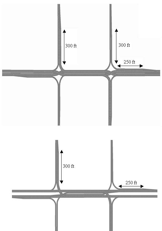
Figure 179 depicts the DCD interchange and conventional diamond interchange configuration. Figure 179. Illustration. Layout of a DCD interchange (top) and a conventional diamond interchange (bottom) in VISSIM®. As noted in table 30, performances at the lower and medium volumes were quite similar for both the DCD interchange and the conventional diamond interchange. However, results from higher volumes show that this conventional diamond had lower throughput, higher average delay per vehicle, higher stop time, and longer queues as compared to DCD interchanges. The results indicated that the maximum off-ramp flows for a DCD interchange (700 veh/h/lane) were greater than the corresponding flows in the conventional diamond (390 veh/h/lane). When off-ramp flows were set at 390 veh/h/lane for a DCD interchange, the service flow for the crossroad increased by 100 veh/h/lane. Table 30. Service volumes of conventional and DCD interchange designs.
Results for the six-lane analysis are shown in table 31, which also included three higher volume scenarios. Service volumes of each of the three designs are shown in figure 28 and table 29. The service volumes for northbound left turns, southbound left turns, eastbound through, eastbound left, westbound through, and westbound left turns are shown. The DCD interchange design did not have any exclusive left-turn lanes unlike the conventional diamond design, and the left-turning vehicles shared the lane with the through movements. The significant difference between the results of DCD interchange and the conventional diamond related to the service volume of left-turn movements. The service volumes of eastbound and westbound left turns and off-ramp left turns for the DCD interchange were almost twice that of the conventional diamond. Table 31. Service volumes and delays for tight diamond (TD) and DCD interchange designs.
Offset ramp terminals were assumed to be about 500 ft; however, the DCD interchange design also worked for shorter offsets. When the offset was reduced to 300 ft for the same signal cycle (100 s), the service volume of northbound and southbound left turns (off ramps) was lower than the capacities obtained for a span of 500 ft, approximately 200 veh/h/lane less for the six-lane design case. Service volumes of all other movements remained unchanged. When a shorter cycle length (80 s) was used, the service volume of these off-ramp left turns decreased by only 100 veh/h/lane, but the service volume of through traffic was reduced by approximately 75 veh/h/lane. In any case, the performance was still better than the corresponding conventional diamond design. The following summarizes the major findings of the study conducted by Bared, Edara, and Jagannathan:(87)
7.6.1 Analysis of Simulation ResultsVISSIM® was used to gain additional insight into the operational performance of the DCD interchange in comparison to a tight diamond (TD) interchange. Three geometric design cases of DCD interchanges and two geometric design cases of TD interchanges were simulated. Table 31 shows the geometric design configurations and volumes of the cases simulated. The lane configurations and geometric features for the DCD interchanges and TD interchanges varied considerably since the number of lanes on the major road approach and bridge deck was different. The vehicular volumes on opposing approaches were balanced (50:50 directional split). The VISSIM® simulation network was 1 mi long on the major and minor road approaches for the cases simulated. In addition to the use of standard defaults in VISSIM®, the following constants were maintained for each simulation:
Based on the VISSIM® simulation results shown in table 31, a DCD interchange processed approximately 6,000 veh/h with a six-lane bridge, while a TD interchange needed an eight-lane bridge to process the same volume. Similarly, a DCD interchange processed approximately 3,700 veh/h with a four-lane bridge, while a TD interchange needed a six-lane bridge to process the same volume. Thus, the DCD interchanges provided tremendous cost savings by having reduced bridge deck sections and conversely increased the capacity of an existing bridge deck. It is important to note that the DCD interchange typically performed better than a TD interchange when the on-ramp left-turn volumes were very high, and the major road through volumes were moderate or directionally unbalanced. Some of the situations where a DCD interchange may be suitable are as follows:
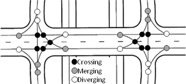
7.7 SAFETY PERFORMANCETheoretically, the DCD interchange design offers a safety benefit due to the reduction in conflict points compared to other interchange forms. As shown in figure 180, a DCD interchange has only 14 conflict points and 2 crossing points. In comparison, figure 181 shows that a conventional diamond interchange has 26 conflict points.(83) Figure 180. Illustration. Conflict points in a DCD interchange.(83)
Figure 181. Illustration. Conflict points in a conventional diamond.(83) Lower design speeds compared to a typical diamond interchange result in lower severity of accidents. Several advantageous safety related features to DCD interchange design were noted by designers of the planned DCD interchange in Kansas City, MO.(84) They included the following:
The concern expressed by designers of the DCD interchange alternative in Kansas City, MO, was that despite the theoretical safety benefits there was limited accident history available to support its use. Furthermore, the driver expectancy issues raised safety concerns that drivers would naturally stay to the right to follow typical vehicular paths, thus traveling into the opposing through travel lanes at the crossovers. Comprehensive tests were performed on the FHWA driver simulator with 74 licensed drivers from the Washington, DC, area of varying ages and sexes. Results from the experiment including the following:
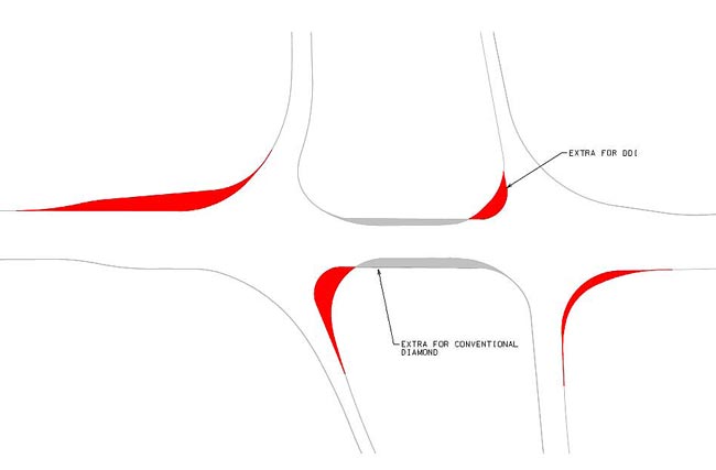
The existing DCD interchange at the intersection of A13 and RD 182 in Versailles, France, has had 11 light injury crashes in the after period of 5 years compared to an average of 23 fatal and injury crashes of a typical diamond interchange in the United States.(88) 7.8 CONSTRUCTION COSTSAs mentioned previously, the ideal comparison of costs and benefits would consist of final construction plans for conventional diamond interchange improvements, the DCD interchange, and other grade-separated alternatives along with an evaluation of operational capacity and safety analysis. Although it is lacking detail and a sufficient number of examples, a basic cost comparison is provided for discussion. The DCD interchange design eliminates the need for exclusive left-turn lanes on the bridge structure as in a conventional diamond interchange. Additional area might be necessary at the nodes of the interchange due to the wide flare resulting from the crossover design, as shown in figure 182. Mobilization, overhead lighting, pavement markings, and drainage costs are not significantly different between the DCD interchange and a conventional diamond interchange. Similar to a conventional diamond interchange, the DCD interchange has two signalized junctions and therefore similar signalization costs. The DCD interchange may require additional signage, lighting, and potential near-side heads. However, this cost is minimal relative to the overall construction costs. Figure 182. Illustration. Footprint comparison of a DCD interchange versus a conventional diamond interchange. Cost estimates were obtained from MoDOT for the proposed DCD interchange in Kansas City, MO, as summarized in table 32.(84) Of the alternatives considered, the TUDI alternative was estimated to cost approximately $11.4 million, with approximately $3.9 million expended for right-of-way. For a similar DCD interchange, the estimated cost was $6.8 million, with approximately $1.5 million for a right-of-way. The DCD interchange design reduced the number of lanes required under the bridge from six to four, eliminating the need to build retaining walls. Also, the DCD interchange design doubled the capacity of the left-turn lanes and eliminated the need for the triple left turn. These factors resulted in tremendous cost savings for the DCD interchange alternative as compared to the TD configuration. Construction costs were generally similar or lower for a DCD interchange than a comparable conventional interchange. However, more conclusive statements could not be taken due to lack of existing interchanges. Table 32. Cost comparison for TUDI and DCD interchange alternatives.
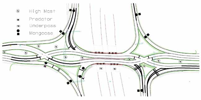
7.9 SEQUENCING OF CONSTRUCTIONImplementing a DCD interchange can cause challenges in maintaining traffic flow during construction. When MoDOT conducted the alternative analyses of the DCD interchange alternative and the current tight diamond interchange, it was concluded that the amount of time required for construction would last one season compared to a TUDI that would be constructed over two seasons. Documentation on specific construction sequencing for the DCD interchange has not been identified. The sequence of steps for one possible approach to construct a DCD interchange is as follows:
Ramp construction depends on how far from the existing ramp alignment the new ramp roadways have been designed. It is likely that narrow travel lanes on existing ramps (use of existing shoulder area, etc.) accommodate the modifications during some portion of the construction. 7.10 OTHER CONSIDERATIONSAgencies contemplating DCD interchange installation should consider other factors in addition to safety, operations, and cost. Such factors include additional lighting, signing, signal heads, enforcement needs, left turn on red policies, and emergency vehicle needs. Roadway lighting for a DCD interchange, like other alternative intersections and interchanges, should be increased. Since the interchange has counterintuitive movements, supplemental lighting is beneficial for unfamiliar drivers trying to maneuver the interchange during nighttime and inclement weather conditions. NCHRP Synthesis 345, "Single Point Urban Interchange Design and Operations Analysis," provides guidelines for roadway lighting for SPUIs.(85) Several features including embedded pavement marking lights, high mast or tower lighting, and illumination levels are discussed in chapter 6, and they can be used as a starting point. Existing lighting standards and specifications outlined in AASHTO's Roadway Lighting Design Guide, FHWA's Roadway Lighting Handbook, and the IESNA publications including Recommended Practices for Roadway Lighting, Recommended Practices for Tunnel Lighting, and Recommended Practices for Sign Lighting can be used for optimal lighting in a DCD interchange. (See references 26–30.) Figure 183 shows the lighting plan for the DCD interchange in Kansas City, MO. Figure 183. Illustration. Lighting plan being implemented at a DCD interchange in Kansas City, MO. Supplemental signing and pavement markings described in section 7.4 are recommended to ensure positive guidance for vehicles traversing the new pathways through the interchange. The FHWA DCD interchange simulation demonstrated that the application of the signs and markings could reduce the anticipated driver confusion and minimize wrong-way maneuvers at a DCD interchange.(83) Enforcement is not expected to be significantly different for the DCD interchange compared to conventional interchanges, although there is no documented or practical experience upon which this is based. Rather, theoretically, a reduction in the number of signal phases and increased efficiency may reduce red light running and congestion-related errant maneuvers. The FHWA DCD interchange simulation also indicated that speeds were effectively reduced for all drivers through the crossover intersections due to the sweeping radii relevant to the design.(83) Therefore, speed compliance would not be likely. One potential problem in the short term may be U-turns at locations where turns are not permitted (if applicable). Because of the lack of familiarity with the DCD interchange following construction, a driver's first intuition after missing a turn or passing a destination may be to perform a U-turn. Emergency vehicle access is not likely to be an issue at DCD interchanges. The larger radii for turns would likely make for easier turning of larger and heavier emergency vehicles. Should access to adjacent parcels be limited (or removed) due to the conversion to a DCD interchange, emergency vehicle routing should be investigated prior to construction. Sight distance for left turns from the off-ramps onto the mainline over the bridge should be reviewed to determine if left turns on red are appropriate. This sight distance can be affected by bridge structure, the skew angle of the interchange, and other roadside obstructions such as lighting and signal equipment. Prior to permitting left turns on red, care should be taken to ensure sight distance is clear to oncoming traffic. Since the DCD interchange is new and has an unusual configuration, advance public involvement is important. News of installation of a DCD interchange should be disseminated among the local population before and during the time of opening. MoDOT is sharing information about the DCD interchange design on their Web site and inviting the general public to open house meetings.(80) 7.11 APPLICABILITYAs with all the designs described in this report, the DCD interchange design is applicable under certain conditions, but not appropriate for all conditions. A primary reason to choose the DCD interchange instead of a conventional diamond interchange is the two-phase signal operation resulting in the ability to process higher left-turn on-ramp volumes. Some of the situations where a DCD interchange may be suitable are listed as follows:
Typically, in suburban and urban settings, limited (or costly) right-of-way and reduced duration of construction are issues. MoDOT has demonstrated that the DCD interchange offered benefits in both of these areas. There are cases where the DCD interchange is not a particularly viable option in urban and suburban areas. In cases where frontage road access (through movement from off-ramp to on-ramp) is needed, the DCD interchange is not preferred. The additional phase would degrade the performance and eliminate the benefit of the two-phase efficient operation. In addition, if progression with nearby signals is required due to proximity, it should be noted that given the operation of the DCD interchange, bidirectional progression may be difficult to achieve. 7.12 SUMMARYThe DCD interchange offers benefits over conventional interchange forms, as follows:
At the time of this report, there were only four DCD interchanges in existence—one in the United States (in Springfield, MO) and three in France. As of this report, MoDOT was planing and about to intiate construction on additional DCD interchanges over the next few years. Their significant contributions to the development of this chapter are recognized. Although driver confusion is the largest concern associated with this design due to the unfamiliar crossover to the left side of the roadway, the FHWA driver simulation of MoDOT interchanges indicated that wrong-way maneuvers, speeds, and red light running were not significant issues. Agencies considering DCD interchanges should be aware of disadvantages of the design relative to conventional interchanges. That is, access to adjacent parcels from the ramps (frontage road access) is not desirable as additional signal phasing reduces the efficiency of the normal two-phase operation. Furthermore, the impact on platoon progression on the arterial crossroad with adjacent nearby signals can be an issue and should be investigated on a case-by-case basis.
|
||||||||||||||||||||||||||||||||||||||||||||||||||||||||||||||||||||||||||||||||||||||||||||||||||||||||||||||||||||||||||||||||||||||||||||||||||||||||||||||||||||||||||||||||||||||||||||||||||||||||||||||||||||||||||||||||||||||||||||||||||||||||||||||||||||||||||||||||||||||||||||||||||||||||||||||||||||||||||||||||||||||||||||||||||||||||||||||||||||||||||||||||||||||||||||||||||||||||||||||||||||||||||||||||||||||||||||||||||||||||||||||||||||||||||||||||||||||||||||||||||||||||||||||||||||||||||||||||||||||||||||||||||||||||||||||||||||||||||||||||||||||||||||||||||||||||||||||||||||||||||||||||||||||||||||||||||||||||||||||||||||||||||||||||||||||||||