U.S. Department of Transportation
Federal Highway Administration
1200 New Jersey Avenue, SE
Washington, DC 20590
202-366-4000
Federal Highway Administration Research and Technology
Coordinating, Developing, and Delivering Highway Transportation Innovations
| REPORT |
| This report is an archived publication and may contain dated technical, contact, and link information |
| Publication Number: FHWA-HRT-12-030 Date: August 2012 |
Publication Number: FHWA-HRT-12-030 Date: August 2012 |
PDF Version (4.44 MB)
PDF files can be viewed with the Acrobat® Reader®
CTE test data were averaged for each aggregate type, and this constituted level 3 inputs for MEPDG. These averages were determined for the entire set of LTPP data as well as for the subset developed by deleting suspect data. A summary of the data is presented in table 47. Table 47 also lists the average PCC CTE for each aggregate type as found in the literature. The data are all in general agreement, providing a degree of confidence in the level 3 MEPDG input recommendations. The average CTE values determined from the data subset are recommended by this study.
|
Aggregate Type |
Average From Literature |
Average From All LTPP Data |
Average From Data Used in Model (Recommended) |
|
Basalt |
4.85 |
5.11 |
4.86 |
|
Chert |
6.55 |
6.24 |
6.90 |
|
Diabase |
4.85 |
5.33 |
5.13 |
|
Dolomite |
5.75 |
5.79 |
5.79 |
|
Gabbro |
4.85 |
5.28 |
5.28* |
|
Granite |
4.55 |
5.62 |
5.71 |
|
Limestone |
4.25 |
5.35 |
5.25 |
|
Quartzite |
6.85 |
6.07 |
6.18 |
|
Andesite |
4.85 |
4.99 |
5.33 |
|
Sandstone |
6.05 |
5.98 |
6.33 |
|
N |
228 |
91 |
|
*There were no samples with a Gabbro aggregate type in the data used in the model. Hence, the average from the entire dataset is recommended.
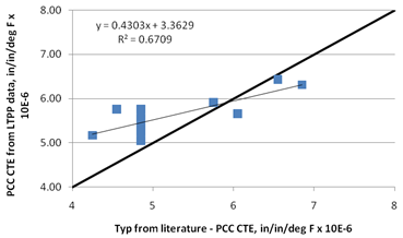
Figure 204 shows a plot of recommended CTE values versus average CTE values obtained from other sources. While they are in fairly good agreement, the values recommended from this study are slightly higher for most cases. This can be explained by the overestimation of CTE during testing.
A step-wise linear regression analysis that considered all PCC variables, which performed within a 5 to 10 percent confidence limit, showed that CTE was most sensitive to aggregate types basalt, dolomite, limestone, and quartzite, as well as to coarse aggregate weight, coarse aggregate specific gravity, and cement content. This demonstrates the influence of mix volumetrics and aggregate type on the predicted CTE values. This validated the approach of developing a model that uses the CTE of individual components with a weighted average by their volumetric proportions.
Volume proportions of each component of the PCC mix were computed using the mix proportioning and mix design data, specifically the amount of each component and the specific gravity. The specific gravities of the coarse and fine aggregates were included in the LTPP database. Air content information was available for only 72 of the 91 cases. Verification for the volumetric proportion calculation showed that for most of the sections, the volumetric proportions summed up closely to 1.0. The average was 1.007, and all values were between 0.93 and 1.08. However, two data points with extremely large coarse aggregate contents (greater than 2,700 lb/yd3) resulted in total volume proportions greater than 1.3, which were suspect data. With the deletion of these data points, the average value was 0.998.
The iterative procedures during the statistical analyses revealed that the model was handling only the volumetric proportions of the coarse aggregate adequately. Therefore, the equation was set up to consider the volumetric proportions of the coarse aggregate, VCA, and that of the mortar (1 - VCA). Because the individual aggregate CTE values were not available, aggregate CTE ranges and means from other sources of literature were used to assign a value to this parameter for each aggregate type.
The following ranges were used to determine the minimum, maximum, and mean for each aggregate type:
The sensitivity of the w/c ratio, a proxy variable to account for the porosity of the paste and hence its ability to expand or contract with change in temperature, was evaluated using the following model form:
Where:
CTEPCC = CTE of the PCC material, inch/inch/°F.
CTECA = CTE of the coarse aggregate, inch/inch/°F.
VCA = Volumetric proportion of the coarse aggregate.
Vmortar = Volumetric proportion of the mortar (1 - VCA).
The regression statistics of this model showed the following:
In subsequent iterations, the analysis procedure attempted to optimize the coarse aggregate CTE value within the range provided above. The model form was reduced to figure 206 or figure 207.
The model statistics are presented in table 48, and details of the range of data used to develop the model are presented in table 49.
The model was established as follows:
![]()
Where:
CTECA = Constant determined for each aggregate type as shown in table 48.
|
Parameter |
Comment |
Estimate |
Standard Error |
95 Percent Confidence Limits |
|
|
c |
No comment |
6.4514 |
0.1889 |
6.0758 |
6.827 |
|
d |
CTECA for basalt |
3 |
0 |
3 |
3 |
|
e |
CTECA for chert |
6.4 |
0 |
6.4 |
6.4 |
|
f |
CTECA for diabase |
3.4835 |
1.2824 |
0.9337 |
6.0333 |
|
g |
CTECA for dolomite |
5.1184 |
0.408 |
4.3071 |
5.9297 |
|
h |
CTECA for gabbro |
3.75 |
N/A |
N/A |
N/A |
|
i |
CTECA for granite |
4.7423 |
0.4188 |
3.9096 |
5.5749 |
|
j |
CTECA for limestone |
3.2886 |
0.3579 |
2.5771 |
4.0001 |
|
k |
CTECA for quartzite |
6.1 |
0 |
6.1 |
6.1 |
|
l |
CTECA for andesite |
3.6243 |
1.4539 |
0.7336 |
6.515 |
|
m |
CTECA for sandstone |
4.5 |
0 |
4.5 |
4.5 |
The model statistics for table 48 are as follows:
|
Parameter |
Minimum |
Maximum |
Average |
|
Coarse aggregate content |
582 |
2730 |
1,811 |
|
Coarse aggregate specific gravity |
2.42 |
2.86 |
2.65 |
|
w/c ratio |
0 |
0.71 |
0.45 |
|
Coarse aggregate volume fraction |
0.13 |
0.62 |
0.41 |
|
Mortar volume |
0.38 |
0.87 |
0.59 |
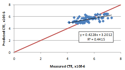
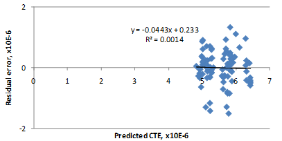
The model has an R2 value of 44.1 percent and an RMSE value of 0.35 psi. The predicted versus measured plot and the residual error plots are presented in figure 209 and figure 210, respectively.


The constant, C, in the model form, determined as 6.4514, is equivalent to CTE of the mortar. (At TFHRC, using the AASHTO TP 60 uncorrected values, a CTE value of 6.2 for mortar containing silica sand was determined. Hence, the value of C is in agreement with the test result.(24)) Since the mortar (all components of the mix design except the coarse aggregate, as per the definition in this equation) occupies a large volume of the matrix, it was necessary for the model to predict higher CTE for increased mortar proportions (or decreasing coarse aggregate proportions). In optimizing the model and selecting the representative CTE for each aggregate type, it was ensured that the CTE of the aggregate is not above C.
Figure 211 and figure 212 show a comparison of the predicted CTE values with average values reported in literature for each aggregate type. The predictions are close, with the model showing a slight bias. The over-prediction observed can be a result of the errors in the CTE test procedure (over-measured CTEs) or could simply reflect the CTE typical of paving mixes. Figure 213 shows the sensitivity of the model to coarse aggregate content. As expected, CTE decreases as the coarse aggregate content increases (or mortar volume decreases). While this is true for most cases, it is also observed that for aggregates with high CTE values, such as chert and quartzite, CTE of the aggregate approaches CTE of mortar, thereby showing little or no sensitivity to coarse aggregate content.
As with all other models, the user is advised to verify model predictions with other sources of information. If possible, both CTE models should be evaluated simultaneously to obtain a range.
