Special Report - Measurement, Prediction, and Mitigation
Appendix B Measurement Procedures
The measurement procedures referenced in the text are provided for easy referral.
Exterior Sound Level Measurement Procedure for Powered Mobile Construction Equipment SAE J88a, SAE Recommended Practice
Report of Vehicle Sound Level Committee approved November 1972 and last revised June 1975. Rationale statement available.
- Scope
This SAE Recommended Practice sets forth the instrumentation and procedure to be used in measuring exterior sound levels for the certification test of powered mobile construction equipment of 20 rated bhp and over. It is not intended to cover operation of safety devices (such as backup alarms), air compressors, jack hammers, pile drivers, pavement breakers, and machinery designed primarily for operation on highways or within factories, aircraft, or recreational vehicles such as snowmobiles and boats. The sound levels obtained by using the test procedures set forth in this SAE Recommended Practice are repeatable and are representative of the higher range of sound levels generated by the machinery under actual field operating conditions, but do not necessarily represent the average sound level over a field use cycle.
- Instrumentation
- A sound level meter which meets the Type 1 or SlA requirements of the American National Standard Specification for Sound Level Meters, S1.4 1971.
- As an alternative to making direct measurements using a sound level meter, a microphone or sound level meter may be used with a magnetic tape recorder and/or graphic level recorder or indicating instrument, providing the system meets the requirements of SAE Recommended Practice J184 QUALIFYING A SOUND DATA ACQUISITION SYSTEM.
- An acoustical calibrator (see paragraph 4.2.4 accuracy within ± 0.5 dB).
- A microphone windscreen shall be used that does not permit the effect on the microphone and frequency response to exceed ± 0,5 dB to 5 kHz and ± 2.0 dB to 12 kHz.
- An anemometer or other device for measurement of ambient wind speed and direction (accuracy within ± 10%).
- A power source rpm indicator (accuracy within ± 2%).
- A thermometer for measurement of ambient temperature (accuracy within ± 1°).
- A barometer for measuring atmospheric pressure (accuracy within ± 1%).
- Procedure
- Test Site The test area shall consist of a flat open space free of any large reflecting surfaces, such as a signboard, building or hillside, located within 30 m (100 ft) of either the microphone or the machinery being measured (see Fig. 1). It is recommended that measurements be made only when the wind speed is below 19 km/h (12 mph).
- The minimum measurement area (see Fig. 1) shall consist of the triangle formed by the microphone location, points A and B, and the rectangle formed by points A, B, C and D. Both designated areas shall be smooth Concrete or smooth and sealed asphalt or a similar hard and smooth surface. The rectangle formed by points C, D, E and F shall consist of hard-packed earth. The planes between the microphone location and line AB and planes encompassed by points A, B, C, F, E and D shall form a continuous, uniform plane. If a minimum measurement area test site is used, it will require reorientation of the machine for each major surface measurement during the stationary tests, and the moving tests will have to be run in two opposite directions. The other option is to have a larger measurement area test site and relocate the microphone for the series of prescribed test conditions with the machine is one position for stationary tests and driving by in only one direction for the moving tests.
- Because bystanders have an appreciable influence on the meter response when they are in the vicinity of the construction machinery or microphone*, not more than one person, other than the observer reading the meter, shall be within 17 m (56ft) of the construction machinery and 1.8m (6 ft) of the measuring microphone, and that person shall be directly behind the observer who is reading the meter, on a line through the microphone and the observer (see Fig. 1).
- The ambient sound level due to sources other than the construction machinery being measured (including wind effects) shall be at least 10 dB lower than the sound level of the machinery being measured. (See paragraph 3.3.3.)
- The surface between and under the construction machinery and microphone shall be smooth and free of acoustically absorptive material, such as snow or grass.
- For all stationary tests the machinery shall be located on the hard surface area formed by points A, B, C and D in Fig. 1.
- MOVING TESTS
- For moving tests of all rubber tired machines, the path of travel shall be across the area denned by points A, B, C and D in the directions shown in Fig. 1.
- For moving tests of all steel wheel, steel drum or track-type machines the path of travel shall be across the area defined by C, D, E and F in the directions shown in Fig. 1.
- Tests Required
- For mobile construction machinery that is used primarily in a stationary mode, test per paragraphs 3.2.1.1, 3.2.1.2, and if applicable 3.2.1.3.
-
For self-propelled construction machinery that is used primarily in a mobile mode, test per paragraphs 3.2.1.1, 3.2.1.2, 3.2.1.3 and 3.2.2. For construction machines which have an auxiliary power source, such as a truck mounted crane, the main engine and auxiliary-engine shall be run separately during tests 3.2.1.1 and 3.2.1.2 with the other engine shut down.
During test 3.2.1.3 only the auxiliary engine shall be run and only the main propulsion engine run during the test prescribed in 3.2.2. For combined construction machinery (such as small loader with backhoe) test per paragraphs 3.2.1.1, 3.2.1.2, 3.2.1.3 and 3.2.2.
- Stationary Tests with Ground Propulsion Transmission Shift Selector in Neutral Position.
- Operate all mobile construction machinery engines at no load with all component drive systems in neutral position and maximum governed speed (high idle at no load) at a stabilized condition.
- Operate all mobile construction machinery engines at no load with all component drive systems in neutral position through the cycle "low idle-maximum governed speed (high idle at no load) low idle" as rapidly as possible, but allowing the engine to stabilize for at least 10 s at maximum governed speed (high idle at no load before it is permitted to return to low idle.
- With the engine at the maximum governed speed (high idle at no load) in a stabilized condition, activate the appropriate hydraulic circuits, mechanical, electrical, hydrostatic, or torque converter drive systems to cycle the major components or component from the most retracted and/ or lowered position to fully extended and/or maximum height position and then back to original position. This cycling should be done as fast as practical, taking into consideration all the pertinent safety factors that can be accomplished without blowing relief valves. For safety reasons and undesirability of change of location of major noise source in relation to microphone, a major portion of the mobile machine, such as the tractor of a scraper unit, drum of a compactor, or the upper rotational structure of an excavator, shall not be moved or placed in a vibratory mode of operation during this stationary machine test.
- CONSTANT SPEED MOVING TEST - Self-propelled construction machinery shall be operated in a forward intermediate gear ratio at no load at a location as specified in paragraphs 3.1.6.1 or 3.1.6.2, The power source shall be operated at full governor control setting. Intermediate is intended to mean second gear ratio for machines with three or four gear ratios, third gear ratio for machines with five or six gear ratios, fourth gear ratio for machines with seven or eight gear ratios, etc. (Gear ratio refers to overall gear reductions.) If there is a problem with the transmission shifting up or down in this phase of this test, one gear lower or higher may be used to eliminate the problem. Hydrostatic or electric drive machinery will be operated as near as possible to one-half its maximum ground speed. Machinery that has major noise-generating components which could be used at the above ground speed, such as on an elevating scraper or on a vibrating compactor, shall have these major components in operation during this moving test.
- Construction machinery that has a major attachment that is normally used for the main operating function shall be equipped with this attachment. Examples of this are buckets on loaders and dozers on either wheel or track-type tractors. For all tests these attachments shall be in a minimum transport position of 0.15 m (6 in.) to 0.3 m (12 in.) for dozers, scrapers, etc., and for loaders use carry position as specified by SAE Standard J732 SPECIFICATIONS DEFINITIONS FRONT END LOADER.
- Measurements
- The microphone shall be located at a height of J.2 m (4 ft) above the ground plane.
- The sound level meter shall be set for slow response and the A-weighting network.
- The ambient wind-speed and direction, ambient temperature, atmospheric pressure, and ambient A-weighted sound level shall be measured and recorded at the height of 1.2 m (4 ft) and within at least 3 m (10 ft) of the one specified location of the microphone as shown in Fig. 1.
- The stabilized maximum governed engine speed shall be measured and recorded.
- The sound level meter needle movement shall be observed during each test sequence at the specified microphone location. The highest value observed, disregarding sounds of short duration that are out of character with the test on the machine, (example) impact sound such as bucket rack against stops, shall be recorded for each test sequence. For stabilized test conditions (3.2.1.1) a single reading shall be recorded for each measurement point. For cycling and moving test conditions (3.2.1.2, 3.2.1.3 and 3.2.2) a minimum of three readings shall be taken for each measuring point. If none of these readings are within 2 dB of each other, then additional readings shall be taken until there are two that are within 2 dB of each other. The reported value shall be the average of these two values that are within 2 dB of each other. If there are two pairs of readings that are within 2 dB of each other, report the average of the higher pair. The final result for each test mode shall be the highest reading for stabilized test conditions and the highest average for the cyclic or moving tests and must include the location of the microphone.
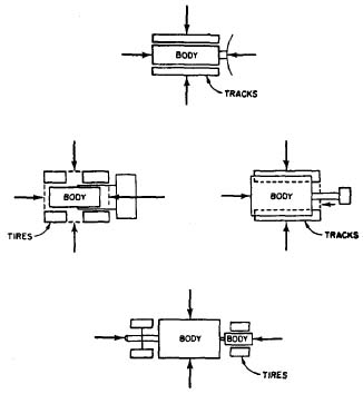
- For stationary tests, record the sound level obtained at a distance of 15 m (50 ft) normal to the centers of the four major surfaces of the equipment at the microphone height. Generally, four major surfaces refer to front, rear, and sides of an imaginary box that would just fit over the machine but does not include attachment items such as buckets, dozers, and booms (see Fig. 2). In the case of a crane or an excavator, the upper (revolving superstructure) fore-and-aft centerline should be in line with the lower fore-and-aft centerline. Operate the machine in a manner as specified in paragraphs 3.2.1.1, 3.2.1.2 and 3.2.1.3.
- For moving tests, take measurements at a distance of 15m (50ft) measured in a direction normal to a major side surface which is parallel to the machine path, as shown in Fig. 1. Operate the machine in a manner specified in paragraph 3.2.2.
- The final reported sound level per this SAE Recommended Practice shall be the highest of the reported values obtained in paragraphs 3.3.6 and 3.3.7; the test report shall include the test mode, the machine operating conditions during the reported test mode, the stabilized maximum governed engine speed, the location of the microphone in relation to the construction machine, the surface description over which the machine operated and the sound level measurements were made.
- General Comments
- It is recommended that persons technically trained and experienced in the current techniques of sound measurements select the instrumentation and conduct the tests.
- Proper use of all test instrumentation is essential to obtain valid measurements. Operating manuals or other literature furnished by the instrument manufacturer should be referred to for both recommended operation of the instrument and precautions to be observed. Specific items to be considered are:
- The type of microphone which shall be oriented with respect to the source so that the sound strikes the diaphragm at the angle for which the microphone was calibrated to have the flattest frequency response characteristic over the frequency range of interest.
- The effects of ambient weather conditions on the performance of all instruments (for example: temperature, humidity, and barometric pressure). Instrumentation can be influenced by low temperature and caution should be exercised.
- Proper signal levels, terminating impedances, and cable lengths on multi-instrument measurement systems.
- Proper acoustical calibration procedure, to include the influence of extension cables, etc. Field acoustical calibration shall be made immediately before and after each test sequence of a piece of construction machinery.
-
References
- ANSI Si.1 1960 (R1971), Acoustical Terminology
- ANSI S1.2 1962 (R1971). Physical Measurement of Sound
- ANSI S1.4 1971, Specification for Sound Level Meters
- ANSI Si.13 1971, Methods for the Measurement of Sound Pressure Levels
- ISO R362 Measurement of Noise Emitted by Vehicles
- SAE Recommended Practice J184, Qualifying a Sound Data Acquisition System
- SAE Standard J732c Specification Definitions Front End Loader
- C.A.G.I. PNEUROP Test Code for Measurement of Sound for Pneumatic Equipment
Applications for copies of the ANSI and ISO documents should be addressed to:
American National Standards Institute, Inc.
1430 Broadway
New York, New York 10018
FIG. 1 TEST SITE CONFIGURATION
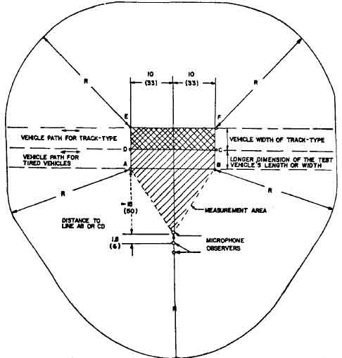
NOTE=R»30(IOO) RADIUS MINIMUM DIMENSIONS ARE M(FT)
FIG. 2 MAJOR SURFACE OUTLINES
Reprinted with permission, "Copyright © Society of Automotive Engineers, Inc., 1976, All rights reserved."
SOUND LEVELS FOR ENGINE POWERED EQUIPMENT - SAE J952b, SAE Standard
Report of Construction and Industrial Machinery Technical Committee approved May 1966 and last revised by Vehicle Sound Level Committee January 1969. Editorial change June 1973
- Introduction - This SAE Standard establishes maximum sound levels for engine powered equipment and describes the test procedure, environment, and instrumentation for determining these sound levels. It does not include machinery designed for operation on highways or within factories and building areas.
- Maximum Sound Levels - See paragraph 5.2 and Table 1.
- Instrumentation
- A sound level meter which meets the requirements of International Electro technical Commission Publication 179. Precision Sound Level Meters.
- A sound level calibrator (see paragraph 5.5).
- A calibrated windscreen (see paragraph 5.4).
- Procedure
- Test Site - The test area shall consist of a flat open space free of any large reflecting surfaces such as a signboard, building, or hillside located within 100 ft of either the microphone or the equipment being recorded.
- Bystanders may have an appreciable influence on meter response if such persons are in the vicinity of the equipment or the microphone. No person other than the observer reading the meter shall be near the microphone.
- The ambient sound level (including wind effects) due to sources other than the equipment being measured shall be at least 10 dbA lower than the level of the tested equipment.
- The path of equipment travel shall be over a surface which is typical of the particular machine application.
- Equipment Operations - Operate the equipment at the combination of load and speed which produces the maximum sound level without violating the manufacturer's operation specifications.
- Measurements
- The microphone shall be located at a height of 4 ft above the ground plane.
- The meter shall be set for "fast" response and the A-weighting network.
- For equipment which is not traveling, record the highest sound level obtained at 50 ft from the nearest surface of the equipment.
- For traveling equipment, take measurements at 50 ft normal from the centerline of the path of straight line travel. The applicable reading will be the highest sound level obtained from the loudest side as the equipment moves along the line of travel.
- The sound level which is reported shall be the average of the two highest applicable readings which arc within 2 dB of each other.
- General Comments
- It is strongly recommended that technically trained personnel select equipment and that tests be conducted only by qualified persons trained in the current techniques of sound measurement.
- An additional 2 dB allowance over the sound level limits is recommended to provide for variations in test site, vehicle operation, temperature gradients, wind velocity gradients, test equipment, and inherent differences in nominally identical vehicles.
- Instrument manufacturer's specifications for orientation of the microphone relative to the source of sound and the location of the observer relative to the meter should be adhered to.
- When a windscreen is required, a previously calibrated windscreen should be used. It is recommended that measurements be made only when wind velocity is below 12 mph.
- Manufacturer's recommended calibration practice of the instruments should be followed. Field calibration should be made immediately before and after each test sequence. Either an external calibrator or internal calibration means is acceptable for field use. Providing that external calibrating is accomplished before or after field use.
- Horsepower sizes utilized in determining equipment categories in paragraph 2 shall be in accordance with SAE J816 or SAE J607.
- Reference Material - Suggested reference material is as follows:
USASI SI.1-1960, Acoustical Terminology.
USASI SI.2-1962. Physical Measurement of Sound
International Electro technical Commission Publication 179. Precision Sound Level Meters (available from USASI):
(Applications for copies of these documents should be addressed to U.S.A. Standards Institute, 10 East 40th Street, New York, N.Y. 10016)
TABLE 1
| Type of Equipment |
Max Sound Level dB(A) at 50 ft (A-Weighting Network) |
| 1. Construction and industrial machinery encompassing only mobile Crawler tractors, dozen, loaders, power shovels, and cranes. trenchers, compactors, scrapers, and wagons |
See SAE J87* |
| 2. Engine powered equipment of 5 hp or less intended for use in residential areas at frequent intervals. Typical pieces of such equipment are lawn mowers, small garden tools, riding tractors, and mow removal equipment. This specifically excludes commercial equipment not intended for frequent use in residential areas |
70 |
| 3. Engine powered equipment exceeding 5 hp but not greater than 20 hp intended for use in residential areas of frequent intervals. Typical pieces of such equipment are llawnmowers, small garden tools, riding tractors, and snow removal equipment. This specifically excludes commercial equipment not intended for use in residential areas. |
78 |
| 4. Engine powered commercial equipment of 20 hp or less intended for infrequent use in a residential area |
88 |
| 5. Form and light industrial tractors |
88 |
| * For tail procedure, see SAE J88. |
Reprinted with permission, "Copyright © Society of Automotive Engineers, Inc., 1976, All rights reserved."
15 January 1976
DRAFT NO. 7
SAE Recommended Practice:
Measurement Procedure for Determining a Representative Sound Level at a Construction Site Boundary Location
- Scope
This SAE Recommended Practice sets forth procedures and instrumentation to be used for determining a representative sound level during a representative time period at selected measurement locations on a construction site boundary. It concerns the community adjacent to the construction site, and it is not intended for use in determining occupational hearing damage risk.
- Introduction
The procedure set forth in this document may be used by construction site management for self regulation and construction site planning or by state and local officials for the enforcement of construction site noise regulations. As is demonstrated in the companion document (Reference 1) to this recommended practice, the representative sound level obtained using this procedure approximates the "energy" equivalent sound level, L , (Reference 2) obtained from more sophisticated data acquisition and analysis techniques. Use of this recommended practice provides sound level data representative of the complex time-varying sounds emitted by construction activities which may be applied using various methods (Reference 1) to estimate community reaction to the construction activity.
- Definitions
- Construction Site
- That area within the defined boundaries of the project. This includes defined boundary lines of the project itself, plus any staging area outside those defined boundary lines used expressly for construction or demolition.
- Boundaries of the Construction Site
- The outermost limit lines of the construction site.
- Noise Sensitive Area
- Inhabited property such as that used for public, commercial, religious or educational purposes, or home dwellings, parks, and other special purpose areas where the background ambient sound is less than the construction site sound level.
- Background Ambient Sound
- The all encompassing sound associated with the given environment, when the construction site is inactive, being usually a composite of sounds from many sources far and near.
- Representative Sound Level, LA
- It is the average of sound level samples accomplished in accordance with procedures outlined in 6.1.1. - 6.1.5.
- Instrumentation
- A sound level meter, which meets Type 1 requirements of the American National Standards Specifications for sound level meters, SI.4-1971 (Reference 3).
- As an alternative to making direct measurements with the sound level meter, a microphone or sound level meter may be used with a magnetic tape recorder and/or graphic level recorder or data analysis instrumentation (either analog or digital) providing the system meets the requirements of SAE Recommended Practice: Qualifying a Sound Data Acquisition System, J-184 (Reference 4).
- An acoustic calibrator with an accuracy of 0.5 decibel (see Paragraph 7.2.4).
- A windscreen (see Paragraph 7.3).
- An anemometer with +10 percent accuracy.
- Site Determination
- Obtain specific drawings, survey stake locations, and other pertinent information in order to sketch the boundaries of the construction site and noise sensitive areas on a facsimile of Figure 1.
- Obtain information in sufficient detail necessary to determine location and activity pattern of the construction site during the period used for measurement, as well as the locations of noise sensitive areas, in order to aid in the selection of sound level measurement locations.
- Measurement
- Sound level measurements at construction site boundary adjacent to noise sensitive areas shall be taken in the following manner:
- Calibrate the sound level meter before and after each measurement period, using an acoustic calibrator.
- Locate the microphone at five feet (1.5m) above the ground and, if practical, 10 feet (3.1m) from walls, buildings, or other sound reflecting structures when they appear at the construction site boundary. When circumstances dictate, measurements may be made at greater distances and heights and closer to walls, providing these facts are noted.
-
Set the sound level meter to the A-weighting network and slow response. Observe the sound level meter during a 10 +2 second sampling period at the start of each minute and one-half minute for any representative 30-minute period of construction activity. If, during any of these observations, the measurements are affected by any intrusive noise sources outside the construction site, such as aircraft, emergency signals, and surface transportation, measurements made during these periods should not be considered, but the number of one-half minute observation periods should be extended until 60 valid measurements are obtained.
On/off highway vehicles, such as dump trucks, truck/mixers, etc., which occasionally enter, operate on, and leave the site, shall be considered as part of the construction activity while within the site boundaries. However, pass-by of such vehicles, in the area of the measurement location causing difficulty in obtaining valid measurements, shall be considered as instructions, and handled as in the preceding paragraph. An alternative measurement system, Paragraph 4.2, may be required to augment the direct measurements for these construction site conditions.
- Tabulate the maximum values, LA observed during the sample period, using a data sheet such as shown in Figure 2.
- Determine the representative sound level, LA, using:
LA = (n∑1 LA) / n
Arithmetic average of LA values.
- LA values
- those sound levels which fall within a range of from 6 decibels less than the maximum level to the maximum level.
- n
- the number of LA values used for computing the arithmetic average.
The use of this technique provides a result which is comparable to "energy averaging" all of the observed values. Corrections may be applied (see Table 1) which results in a computation of L for the representative measurement period.
- General Comments
- It is often desirable to obtain the background ambient sound level on the same day as the sound survey to obtain representative .construction site sound levels. It is suggested that this be accomplished when the construction site is inactive, such as before start-up, during the luncheon break, or after shutdown. The above procedure (6.1.1-6.1.5) should be used.
- It is recommended that persons technically trained and experienced in the current techniques of sound measurements select the equipment and conduct the tests.
- Proper usage of all test instrumentation is essential to obtain valid measurements. Operating manuals or other literature furnished by the instrument manufacturer should be referred to for both the recommended operation of the instrument and precautions to be observed. Specific items to be considered are:
- The type of microphone, its directional response characteristics, and its orientation relative to the ground plane and source of noise.
- The effects of ambient weather conditions on the performance of all instruments (for example, temperature, humidity, and barometric pressure). Instrumentation can be influenced by low temperature and caution should be exercised.
- Proper signal levels, terminating impedances, and cable lengths on multi-instrument measurement systems.
- Proper acoustical calibration procedure, to include the influence of extension cables, etc. Field calibration shall be made immediately before and after each test sequence. Internal calibration means is acceptable for field use, provided that external calibration is accomplished immediately before or after field use.
- A microphone windscreen shall be used provided that its effect on the total sound level measuring system does not degrade the system below the requirements of ANSI SI.4-1971, for Type 1 sound level meters. It is recommended that measurements be made only when wind velocity is below 12 mph (19 km/hr).
- Measurements should not be made if significant changes in extraneous and non-construction related noise-making activities or patterns occur during the sampling period. Examples of changes in noise-making activities or patterns which affect the data are:
- Nearby noise sources, such as power mowers, pavement breakers, brush cutters, or power saws.
- Changes in vehicular traffic flow, such as closed street, detours, or shift-change periods near industrial plants.
References
- Companion Document SAE Report # , date
- EPA, Information on Levels of Environmental Noise Requisite to Protect Public Health and Welfare with an Adequate Margin of Safety, 550/9-74-004, March 1974.
- American National Standard SI.4-1971, Specifications for Sound Level Meters.
- SAE J184 Sound Level Acquisition System.
- American National Standard SI.1-1960, Acoustical Terminology
- American National Standard SI.2-1962, Physical Measurement of Sound.
Table 1
Corrections to LA to Obtain Leq
| n/60 |
Correction -dB |
| .8 to 1 |
0 |
| .7 to .8 |
-1 |
| .6 to .7 |
-2 |
| .5 to .6 |
-3 |
| .4 to .5 |
-4 |
| .3 to .4 |
-5 |
| .2 to .3 |
-7 |
| < .2 |
-10 |
Figure 1 Sample Sketch Format
|
(Construction Site)
- Sketch Appropriate Site Boundaries, Adjacent Communities, and Measurement Locations.
- Construction Site ___________________________________________________________________ Type ____________________________
- Sound-Level Meter: Manf. ____________________________ Model ____________________________ S/N ___________________________
- Weather Conditions __________________________________________________________________________________________________
- Remarks ___________________________________________________________________________________________________________
|
Figure 2 Sample Construction Noise Exposure Data Sheet
Construction Noise Exposure Data Sheet
Instructions:
- Calibrate sound-level meter using acoustic calibrator.
- Install wind screen. select A weighting network. select "slow" response.
- Observe for 10±2 seconds at the start of each minute and 1/2 minute for 30 minutes.
- Tabulate maximum reading La.
Construction: ( ) Activity ( ) No Activity
Determine Arithmetic Average LA
LA(dBA)
- ____________________________
- ____________________________
- ____________________________
- ____________________________
- ____________________________
- ____________________________
- ____________________________
- ____________________________
- ____________________________
- ____________________________
- ____________________________
- ____________________________
- ____________________________
- ____________________________
- ____________________________
- ____________________________
- ____________________________
- ____________________________
- ____________________________
- ____________________________
- ____________________________
- ____________________________
- ____________________________
- ____________________________
- ____________________________
- ____________________________
- ____________________________
- ____________________________
- ____________________________
- ____________________________
|
- ____________________________
- ____________________________
- ____________________________
- ____________________________
- ____________________________
- ____________________________
- ____________________________
- ____________________________
- ____________________________
- ____________________________
- ____________________________
- ____________________________
- ____________________________
- ____________________________
- ____________________________
- ____________________________
- ____________________________
- ____________________________
- ____________________________
- ____________________________
- ____________________________
- ____________________________
- ____________________________
- ____________________________
- ____________________________
- ____________________________
- ____________________________
- ____________________________
- ____________________________
- ____________________________
|
SUM:*_____________________
*Consider for the sum only these values within 6 dB(A) of the maximum value observed.
LA = Sum/n
Construction Site _______________________________________________ Date ____________________ Type ____________________
Wind Velocity ___________________________mph. Temperature ________________________ F. Engineer _______________________
Remarks ________________________________________________________________________________________________________
________________________________________________________________________________________________________________


