
When noise enters a building from the outside, it undergoes a reduction in level we have defined as Noise Reduction (NR). The amount of NR obtained depends on the type of construction used for the walls of the building, the sizes and types of windows and doors, the presence of noise leaks such as ventilation openings, and the amount of acoustically-absorptive material inside the building. Noise Reduction can be measured directly (this is discussed in Chapter 3), or it may be calculated from the following relation:
where:
EWNR = Exterior Wall Noise Rating.
10 log (S/A) = Room Absorption Factor.
The Exterior Wall Noise Rating (EWNR) is a scheme for evaluating the Transmission Loss (TL) of a building element based on a typical highway noise spectrum.* In a typical building, many walls have windows and doors so that the EWNR must be known for these elements. Furthermore, the composite EWNR must be determined for the wall system with windows and doors installed. This chapter contains EWNR values for commonly-used wall constructions, window and door units, and miscellaneous elements such as through-the-wall air conditioners. In addition, procedures are included for combining the effects of two or more elements to determine the composite EWNR. Finally, a step-by-step procedure is given to evaluate the Noise Reduction value in the above relation. Material contained in this chapter can also be used to select building modifications to increase Noise Reduction to the desired amount. The steps of the overall manual procedure that will be carried out in this chapter are shown in Figure 5, where Lo is the given highway noise level and Lc is the design noise level.
*See Appendix A for details on the development of the Exterior Wall Noise Rating concept.
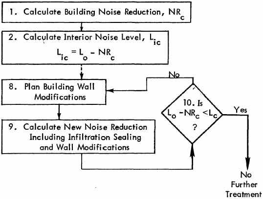
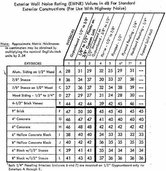
Table 1 is a matrix presentation of EWNR values of 91 commonly-used basic exterior wall constructions, each made up of an exterior and an interior surface with no absorptive material in the stud space. The matrix may be entered either on the horizontal listing of interior wall surfaces or on the vertical listing of exterior wall surfaces.
Typical constructions found in existing buildings are often a variation of one of the basic constructions listed in Table 1. For example, an existing building may have fiberglass insulation in the stud spaces, or the stud spacing may be 24 inches rather than 16 inches. For this reason, it is convenient to consider standard constructions as having a basic EWNR value with some additional value added to account for construction variations. This approach may also be used to determine the NR benefits that may be expected by modifying an existing construction.
Modifications to basic constructions usually involve changes to the weight per unit area of wall panels, addition of absorption to the stud space, or changes to the limpness of the wall panels. These three modification categories act independently and when modifications are made to different categories, the full benefit of each modification will be realized. Adjustments to be added to the EWNR for basic constructions are given in Table 2 for the three categories. Category 3 contains several different modifications that increase the limpness of a construction. If two or more Category 3 modifications are used, count the value of the largest adjustment plus one-half of the value of the next largest adjustment.

|
|
|
To obtain the Total EWNR adjustment for multiple modifications: add the adjustments for each of the three categories. If more than one Category 3 modification is used, count the value of the largest adjustment plus one-half of the value of the next largest.
If fiberboard is used for a Category 3 modification, count Category 2 stud space absorption as only 2 dB.
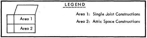
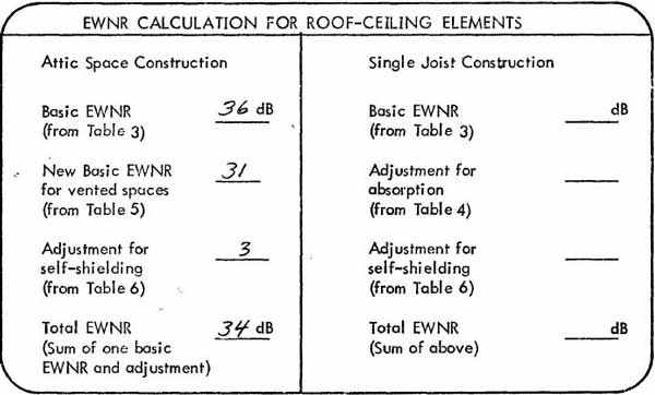
If the room being evaluated is just below the roof, the EWNR of the Roof-Ceiling Construction must be determined. Two general types of Roof-Ceilings in common use are the Single Joist and Attic Space Type, as shown in Figure 6.
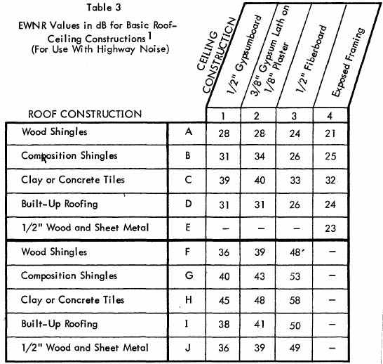
Basic EWNR values for Typical Roof-Ceiling Constructions are given in Table 3 for Single Joist as well as Attic Space Constructions. These basic values must be adjusted to account for attic venting, acoustical absorption in the attic or ceiling joist space, and self-shielding of the roof by the building.
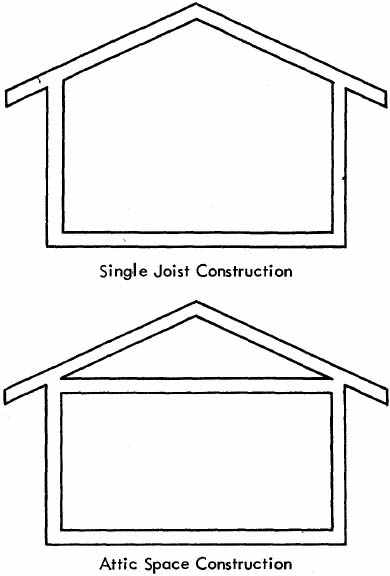
Figure 6. Illustration of Two Commonly-Used Roof-Ceiling Constructions
If the roof system is not vented and is lined with acoustically absorptive material (such as fiberglass or mineral wool), add an adjustment from Table 4 to the basic EWNR value.
| Description | Adjustment Factor, dB(To be Added) |
|---|---|
| Single Joist Constructions- All Cases | 5 |
| Attic Space Constructions - Fiberboard Ceiling Plaster or Gyp Ceiling | 2 6 |
If the roof system is a vented attic space system, use Table 5 to adjust the EWNR values. Find the row corresponding to the basic EWNR value from Table 3 and read the new EWNR value in the appropriate column to account for the absorptive material. Single joist constructions are not normally vented, so Table 5 does not apply to these systems.
| Basic Construction EWNR, dB | Vented Attic EWNR, dB(Without Absorption) | Vented Attic EWNR, dB(With Absorption) | |
|---|---|---|---|
| Plaster or Gypboard Ceiling | 36 to 39 40 to 42 43 to 45 46 to 48 | 24 25 26 27 | 31 32 33 34 |
| Fiberboard Ceiling | 48 to 58 | 35 | 38 |
Finally, the Roof-Ceiling EWNR values must be adjusted to account for building self-shielding which is a function of the slope of the roof line. The noise level due to an exterior source will not be as great just outside the center of the building roof as it will be just outside the building walls. This self-shielding effect of the building may be accounted for by adding the adjustment factors given in Table 6 to the EWNR values determined in Tables 3, 4, and 5.
| Roof Line Description | Adjustment Factor, dB(to be added) |
|---|---|
| Flat Roof Sloped Roof | 6 3 |
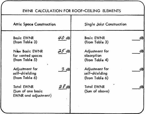
If absorption were added to the vented attic space, the use of Table 5 indicates an EWNR of 32 dB. With the adjustment for self-shielding, the resulting EWNR is 35 dB. The absorption has provided a beneficial increase in the EWNR of 7 dB.
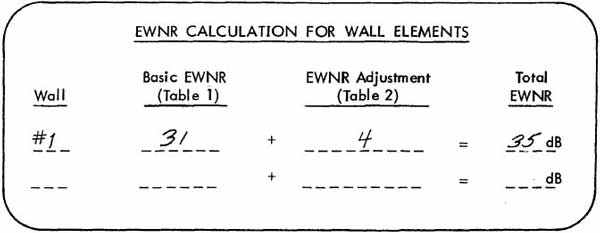
These calculations should be carried out on Worksheet No. 1,a portion of which is reproduced as follows. (A complete Worksheet No. 1 is included at the end of the manual.)
If the wall being evaluated has one or more windows or doors/ the EWNR values of these elements must be determined. Table 7 lists EWNR values for common window assemblies and Table 8 lists EWNR values for commonly-used doors.
| DESCRIPTION | EWNR, dB | |
|---|---|---|
| Single Glazed Windows | 1/16" glass (.16cm) 1/8" glass (.32 cm) ¼" plate glass (.64 cm) 5/16" glass (.79 cm) 3/8" glass (.95 cm) 2-ply glass, 0.53" total (1.35cm) 3-ply glass, 0.82" total (2.1 cm) | 24 24 24 28 30 38 41 |
| Jalousie Window | 4-½" wide, ¼" thick louvers with ½" overlap - cranked shut | 18 |
| Double Glazed Windows | 3/32" glass, 4" airspace, 3/32" glass 1/8" glass, 2-¼" airspace, 1/8" glass 1/8" glass, 2-¼" airspace, ¼" .glass ¼" glass, 2-¼" airspace, ¼" glass 3/16" glass, 2" airspace, ¼" glass ¼" glass, 2" airspace, 3/8" glass 3/16" glass, 2" airspace, 3/8" glass 3/16" glass, 4-¾" airspace, ¼" glass | 30 32 36 38 39 40 41 44 |
Note: The addition of a storm window to an existing single glazed or jalousie window will increase the EWNR by 5 dB.
*If the window is fully open (such as a fully open jalousie or crank type window) its EWNR value is 4 dB. If the window is not completely open (usually the case for sliding windows) use 4 dB for the open area, the given value for the closed or unopenable area, and combine the two values using the procedures of Section 2.6.
| DESCRIPTION | EWNR, dB | |
|---|---|---|
| Hollow Core Doors | 1-¾" wood,1/16" undercut 1-¾" wood, Weather- Stripped Steel (3.22 Ibs/ft²,15.72 kgs/m²)Magnetic weather-strip | 16 17 28 |
| Solid Core Doors | 1-¾" wood,1/16" undercut 1-¾" wood, Weather- Stripped 1-¾" wood, Drop seal threshold 1-¾" wood, weather-strip, and Aluminum storm door, glazed 1/16" glass | 18 26 35 31 |
| Sliding Door | Glazed 3/16" (.48 cm) safety glass | 26 |
Note: The addition of a weather-stripped single glazed storm door to an existing door will increase the EWNR by 5 dB.
If a through-the-wall-type air conditioning unit is present in an existing wall being evaluated, or if such a unit is being considered, the EWNR values of the air conditioners must be determined. Table 9 lists EWNR values for through-the-wall air conditioners for vents open and vents closed. Treat these units as windows in the remaining analysis in this manual.
| Vent Open | Vent Closed | |
|---|---|---|
| EWNR, dB | 21 | 24 |
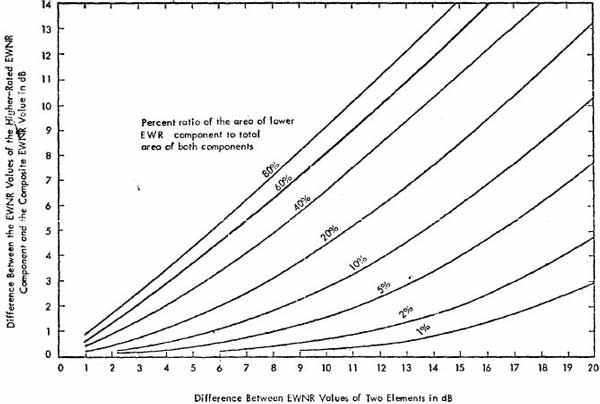
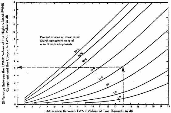
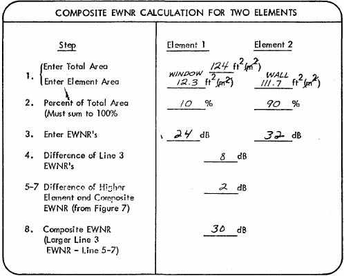
In most typical constructions of interest, there will be one or more windows, doors, and through-the-wall air conditioners existing as part of the walls being evaluated. Two components - such as a single door in a wall - may be combined and treated as one single component with an EWNR value that is less than the EWNR of the higher-rated element. The amount by which the EWNR of the higher rated element (usually the wall) must be reduced to account for the presence of the lower-rated element (usually the window or door) is a function of the relative areas of both components and the magnitude of the difference between their individual EWNR values.
For more than two components, the following procedure may be repeated as many times as necessary taking the elements two at a time in any order.
PROCEDURE To Combine the EWNR Values of Two or More Elements
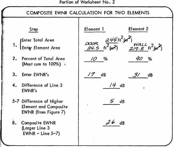
These calculations should be carried out on Worksheet No. 2, a portion of which is reproduced as follows. (A complete Worksheet No. 2 is included at the end of the manual.)
When exterior noise is transmitted to the interior of a structure, it undergoes absorption due to materials located in the room such as draperies, carpeting, and upholstered furniture which usually provide most of the absorption in typical buildings.
Increasing the interior room absorption in an attempt to reduce noise produced by an exterior source is not usually an effective technique, since a great deal of absorption must be added to an existing interior space to obtain only a small noise reduction benefit.
The presence of normal amounts of interior room absorption must be accounted for, however, when determining the noise reduction of an existing structure. The value of the adjustment for room absorption will depend on the total amount of absorption usually referred to by the term A and the total surface of the exterior wall, S (this is the area of the exterior wall that covers the room being evaluated).It is not necessary to actually determine what S and A are, since the combined room absorption adjustment - 10 log (S/A) - is normally a constant value for various types of rooms in typical structures. (See Appendix C for a detailed discussion of this.) Adjustment factors for room absorption are listed in Table 10 for three types of rooms with either one exterior wall or two exterior walls (corner rooms).
| Type of Interior Room | 10 log (S/A), dB | |
|---|---|---|
| 1 Exterior Wall | 2 Exterior Walls (Corner Room) | |
| Living Room | -4 | -1 |
| Bedroom | -3 | 0 |
| Kitchen | -2 | +1 |
Once the appropriate EWNR values are determined for the structure, the Noise Reduction (NR) can be calculated from the following relationship
where 10 log (S/A) is the room absorption correction factor given in Table 10. Use the following procedure to determine the NR for an existing structure or for one that is being modified.
| 1. | For the bedroom, noise will be transmitted through one wall, the roof-ceiling, and the window. | |
|---|---|---|
| 2. | Window: 12.3 square feet (1.1 m²) | |
| Wall: 111.7 square feet (10.4m²) | ||
| Ceiling: 186.0 square feet (17.3m²) | ||
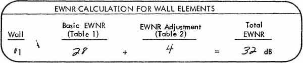
| 3. | Basic Wall EWNR (Construction A1 from Table 1) | 28 dB |
| Adjustment for Stud Space Absorption (from Table 2) | +4 | |
| Wall EWNR | 32 | |
| 4. | Basic Roof-Ceiling EWNR (Construction Fl from Table 3) | 36 dB |
| New EWNR for Vented Attic (from Table 5) | 31 | |
| Adjustment for Slope (from Table 6) | +3 | |
| Roof-Ceiling EWNR | 34 dB | |
| 5. | Window EWNR (from Table 7) | 24 dB |
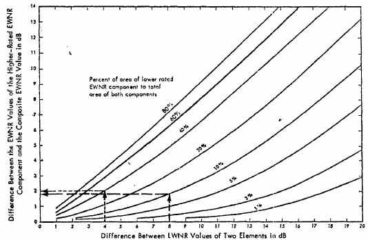
| 6. | The window (10 percent of the combined window-wall area) has an EWNR that is 8 dB less than the wall EWNR. Figure 7 indicates that the difference between the wall EWNR and the composite EWNR is 2 dB. The composite wall-window EWNR is, therefore, 32 - 2 =30 dB. | |
| 7. | This step is not applicable in this case. | |
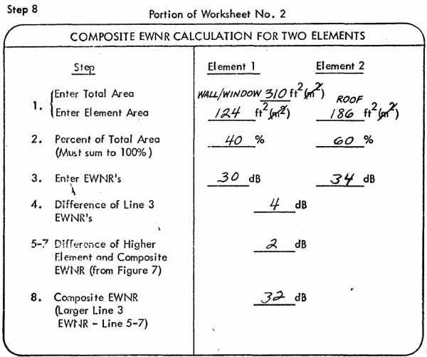
| 8. | The roof-ceiling EWNR is 34 dB and the composite wall-window EWNR is 30 dB. The total ceiling and wall-window area is 186 + 124 = 310 square feet (11.5 + 17.3 = 28.8m²), 40 percent of which is the wall-window (the lower-rated element). Figure 7 indicates that with a difference of 4 dB between the EWNR values of the two elements, the higher-rated element EWNR exceeds the composite total EWNR by 2 dB, The composite total EWNR for the structure is, therefore, 34 - 2 = 32 dB. | |
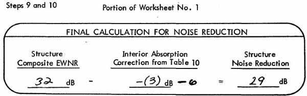
| 9. | The room absorption correction from Table 10 for a bedroom with one wall exposed is -3 dB. | |
| 10. | The NR is determined by subtracting the absorption correction from the structure's EWNR (NR = EWNR - 10 log S/A - 6). Therefore, NR = 32 - (-3) - 6 = 29dB. | |
These calculations should be carried out on Worksheet No. 1 and Worksheet No. 2, portions of which are reproduced as follows: (Complete Worksheets are included at the end of the manual.)
Steps 1 to 3 Portion of Worksheet No. 1
Step 4 Portion of Worksheet No. 1
Steps 5 and 6 Portion of Worksheet No. 2
When interior noise (from nearby highways) exceeds the Design Noise Level, modifications to increase the building's noise reduction are required. A preliminary selection of modifications can be made by considering the three basic paths by which noise enters a structure. The actual increases in noise reduction which would result from these modifications can then be determined using methods presented earlier in this chapter. If insufficient noise reduction is obtained, the cycle of selection and evaluation should be continued until interior noise no longer exceeds the Design Noise Level.
The three major paths by which noise can be transmitted to the interior of a structure are illustrated conceptually in Figure 8. These paths are:
Air infiltration paths are the small gaps and cracks that normally exist around doors and windows. Naturally, the more such leakage paths there are, the lower the noise reduction of the building will be - even if the EWNR of the wall panels themselves is relatively high. This explains why it is often not sufficient simply to calculate the interior noise level using known properties of wall materials, because this method cannot easily take leakage into account. The usual calculated value of interior noise provides the minimum value that can be obtained in the absence of leakage paths. Thus, the principal difference between the calculated and appropriately measured values of interior noise may be attributed to noise leakage. The improvement in NR that can be obtained merely by treating the leakage paths without modifying the windows, doors, or other building elements is shown, in Table 11, to be as high as 4 dB. Thus, the usual first step in increasing the NR of buildings is to
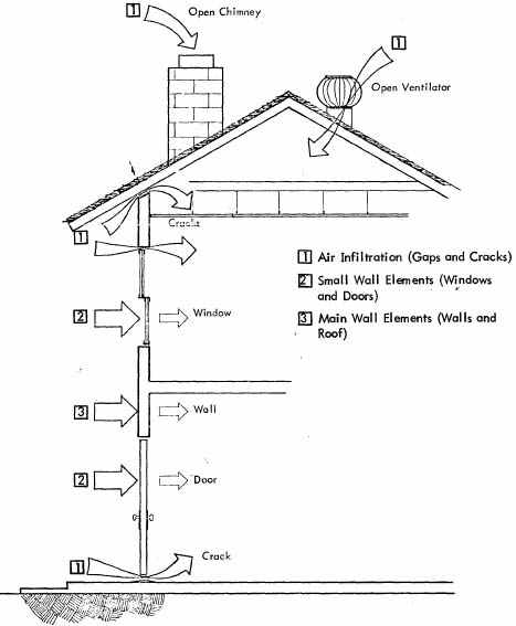
Figure 8. Conceptual Illustration of the Three Major Types of Paths By Which Noise is Transmitted to Building Interiors.
seal all infiltration cracks using weather-stripping, nonhardening caulking, and door threshold seals. If the sealing of cracks and leaks will not add sufficiently to the NR of the building, then modifications of the building elements will be required.
Since small wall elements such as windows and doors usually have EWNR values less than that of the surrounding wall, it is usually beneficial to consider them in the second stage of modifications. This second stage should upgrade small wall elements to an EWNR which approaches that of the surrounding wall. This is usually done by replacement with improved elements and, as shown in Table 11, can result in NR increases of up to 10 dB. One basic small element modification is the installation of storm doors and windows. These can provide substantial increases in door and window EWNR, but these elements must remain in place if the benefits are to be realized year-round.
The final alternative, if the previous two approaches do not provide adequate noise reduction, is modification of the main wall elements, the basic* - wall and roof construction. This major noise attenuating technique can provide substantial increases in NR but may not be justifiable on a cost/benefit basis. Two of the simpler construction modifications are addition of absorbing material to the stud space, and resilient mounting of the interior wall panels. The NR benefits to be expected from these and more extensive modifications can be obtained from tables presented earlier in this chapter.
Table 11 may be used to select the modification type based on the required increase in NR. .Relative modification costs are also included to assist in this selection. Procedures for estimating quantitative changes in heating and ventilation requirements due to the modifications are presented in Chapter 4, and procedures for estimating the actual costs of various modification alternatives are given in Chapter 5.
| Noise Reduction Modification | Increase in NR of Structure | Initial Modification Cost | Additional Ventilation Required | Heating and Air Conditioning Energy Savings |
|---|---|---|---|---|
SEAL LEAKS Seal all cracks, openings, leaks with caulk, tape, weather-stripping around door, window, wall joint seams. Provide acoustical baffles for chimneys, ventilators, etc. | Up to 4 dB | Low | High | High |
SMALL ELEMENT MODIFICATION For windows, doors, air conditioners, ventilators, install new elements with upgraded EWN R comparable to that of wall structure . | Up to 10 dB over sealing of cracks; typically, 4 to 7 dB. | Moderate | None | Moderate |
WALL PANEL MODIFICATION Construction changes to walls, roof, including stud space insulation and resilient mounting of interior surface . | Up to 10 dB over small element modifications; higher for more extensive modifications. | High | None | Moderate |


 EWNR, dB