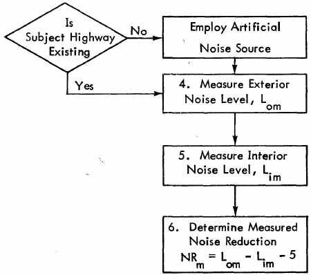
Procedures were given in Chapter 2 to calculate Building Noise Reduction, NRc Since the Exterior Noise Level, Lo, is given, the calculated NR may be used to calculate the building's Interior Noise Level, Lic When Lic safety margin of the Design Noise Level, measurements should be made to establish the Measured Interior Noise Level Lim and the Measured Exterior Noise Level. Lom, at the wall (assumed equal to the free field Exterior Noise Level Lo +5 dB) in order to define the Measured Noise Reduction (NRm = Lom - Lim - 5).
This chapter discusses the equipment and procedures necessary for measuring noise levels. That portion of the overall Manual procedure dealing with noise measurements is shown in Figure 9.
One area of environmental acoustics that has received considerable attention in recent years is the development of new methods to describe the impact of highway noise on the community. Attempts to correlate noise environments with community annoyance have led to the development of several single-number noise descriptors for the assessment of community reaction. To accurately relate to peoples' reactions to noise/ a descriptor should describe the fluctuating noise completely by including intensity and frequency characteristics and the variation of both with time. Furthermore, it should describe, in a single number, the known effects of noise on humans.
A descriptor that satisfies these requirements is the Equivalent Noise Level, Leq, which is the constant noise level that contains the same amount of acoustical energy as the actual fluctuating level of interest over the same period of time. Leq values are usually based on A-weighted noise levels. Community response to noise has been widely correlated to A-weighted L values, and reliable methods of predicting highway noise levels expressed in Leq have been developed. Procedures are given in this chapter to obtain Leq values from manually-sampled noise level data that may be obtained with a hand-held sound level meter.
There is a wide range of instrumentation available for the measurement and analysis of highway noise. Some units, such as a hand-held sound level meter (SLM), can provide simple noise level data without the necessity for laboratory data reduction. To obtain records of data representing long periods of time, it is frequently advantageous to have data recorded and analyzed in a laboratory. The highway planner, however, will seldom have available equipment more complex than the hand-held SLM. Thus, the measurement techniques given in this chapter will primarily be concerned with the use of a sound level meter.
In addition to the SLM, a calibrator, microphone windscreen, and stopwatch will be necessary to perform adequate measurements. To insure sufficient precision, the meter should be certified as a Type I or Type II sound level meter according to ANSI Standard SI.4-1971.¹ Further, the meter should be capable of measuring noise levels ranging from 35 to 100 dB. The meter and microphone should be calibrated prior to making the measurements and again when the measurements have been completed. The microphone windscreen is necessary to reduce wind noise and to protect the microphone from moisture and dust. A stopwatch or clock with a readable sweep-second hand will be required to time the meter readings.
Specific measurement procedures will depend on whether the highway is existing. If it is still in the planning stage, then an artificial source must be used. This procedure will be discussed later in this chapter.
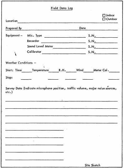
It is advisable to maintain a Field Data Log similar to that shown in Figure 10. All pertinent information should be entered on the log for each measurement site prior to recording data.
If traffic flow is fairly constant throughout the measurement period, measurements can be taken - first outside, and then inside the building - with the same meter, since the source noise level will not have changed. A final-check measurement should be made outside to verify that conditions have not changed, however. If traffic conditions do not allow for this, simultaneous exterior and interior measurements must be taken, using a separate SLM for each location.
To record exterior noise levels, use the following procedure:
For all noise level measurements made during these procedures, the meter should be set to the "slow" response setting.
If the room of interest has more than one exterior wall, choose the one most directly facing the highway for exterior measurements. Locate the microphone or sound level meter as close as possible to the center point (both horizontally and vertically) of the exterior wall area of the room as shown in Figure 11. This location should be adjusted, if required to maintain at least three feet (91 cm) between the microphone and any surfaces perpendicular to the wall such as fences, awnings, or deep window perimeters. An extendable microphone stand may be necessary to hold the microphone at this location for the required measurement duration. Hold the microphone or fix it in a stand as close to the wall surface as possible without touching it. The microphone face should be perpendicular to the wall. If a soft foam microphone windscreen is used, it may be lightly compressed
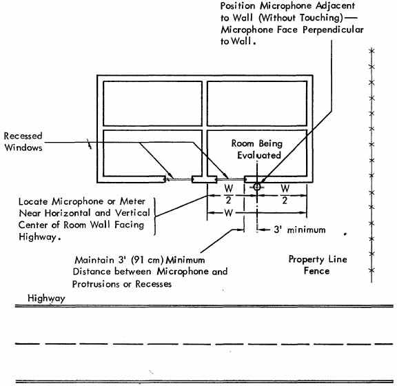
Figure 11. Location of Sound Level Meter and Microphone for Exterior Noise Level Measurements.
against the wall in positioning the microphone as closely as possible. When making measurements with a hand-held SLM, hold the meter at a comfortable arm's length away from the body, with the microphone positioned as above. Never stand between the meter microphone and the noise source.
Because weather and atmospheric conditions can affect noise measurements, data should not be recorded under conditions of precipitation, ground fog, or when wind velocity exceeds 12 mph (19 km/hr). Additionally, measurements should not be made when the highway is covered with rain, snow, or ice.
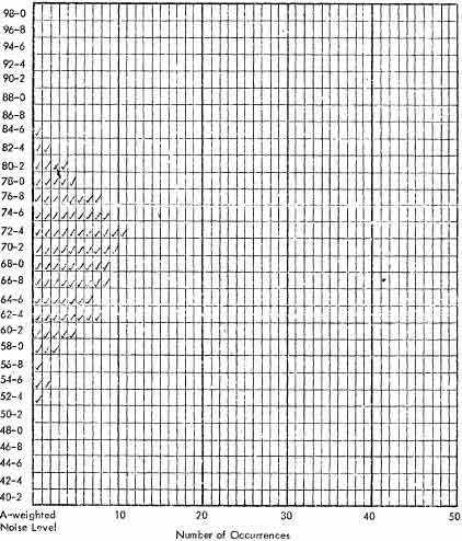
During the actual measurement, the meter indication should be noted every 10 seconds. These values should be recorded as a check mark in the appropriate 2 dB-interval row on a Field Measurement Data Sheet, such as that shown in Figure 12. Even-numbered readings should be recorded in the higher row; for example, if the meter indicates a reading of exactly 62 dB, a check should be made in the row labeled 62-4. This measurement sampling should be continued for at least 15 minutes at each location. If the readings seem to fluctuate quite a bit, or if traffic flow is moderate-to-light (less than 1200 vehicles per hour total), the measurement sampling period should be increased to 30 minutes.
To record interior noise levels, use the following procedure:
When making interior measurements, the noise level within the room will normally vary slightly between different locations due to the acoustical characteristics of the walls and room interior. To select a measurement location, quickly survey the room interior with the SLM. Identify a position at about shoulder-height, away from large reflecting surfaces, where the sound level approximately represents the average for the entire room. This point will normally be near the center of the room.
Once the exterior and interior noise levels have been measured by the sampling technique discussed in Sections 3.4.1 and 3.4.2, the next step is to compute an Leq value for both exterior and interior noise. The Leq value may be computed with the use of a calculator, or the computation may be carried out manually.
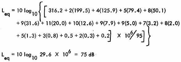
If a calculator is available, the Leq of a number of discrete A-weighted noise levels for a specified time period is given by:
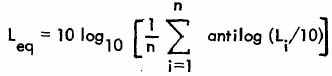
where Li is the instantaneous noise level for sample i and n is the number of samples in the sampling time period.
| Li | Number of Samples | Antilog Li/10 |
|---|---|---|
| 85 | 1 | 316.2 x 10⁶ |
| 83 | 2 | 199.5 |
| 81 | 4 | 125.9 |
| 79 | 5 | 79.4 |
| 77 | 8 | 50.1 |
| 75 | 9 | 31.6 |
| 73 | 11 | 20 |
| 71 | 10 | 12.6 |
| 69 | 9 | 7.9 |
| 6V | 9 | 5 |
| 65 | 7 | 3.2 |
| 63 | 8 | 2 |
| 61 | 5 | 1.3 |
| 59 | 3 | 0.8 |
| 57 | 1 | 0.5 |
| 55 | 2 | 0.3 |
| 53 | 1 | 0.2 |
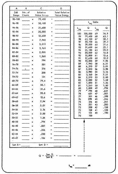
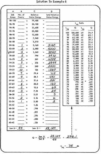
If a calculator is not available, the worksheet illustrated in Figure 13 may be used to determine Leq values manually. Use the following procedure to determine Leq complete this worksheet:
The procedures described so far in this chapter will not be applicable when a yet-to-be-constructed highway is being evaluated, or when the traffic on an existing highway does not produce noise levels that exceed the ambient level by 10 dB. Under these circumstances, some type of artificial source of noise will have to be employed for Noise Reduction measurements. Two types of artificial noise sources will be considered in this section - the use of a diesel truck (or motorcycle), and the use of a loudspeaker system to play back tape-recorded highway noise.
If a truck is selected as an artificial source, it may either be run in neutral at a constant engine speed for separate exterior and interior measurements, or it may be driven past the building. If a moving source is used, simultaneous exterior and interior measurements will be necessary.
If an artificial noise source is used to determine Noise Reduction, the levels measured from the operating source must be at least 10 dB above the ambient noise level without the artificial source. This applies to both interior and exterior measurements.
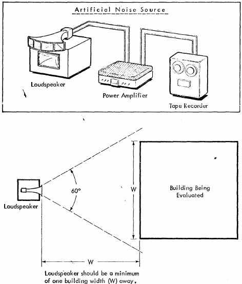
If a loudspeaker system is desired, the required equipment can usually be rented from electronics or instrumentation dealers. The system will consist of a tape-deck, a power amplifier with a minimum power rating of 30 watts, and the loudspeaker itself, as illustrated in Figure 14.The loudspeaker should have a minimum horizontal dispersion of 60° as indicated in the illustration, and a relatively good frequency response between 50 Hz and 5 kHz. As a guide, a loudspeaker system capable of generating a sound pressure level (SPL) of 100 dB at 50 feet should be adequate. However, in particularly noisy areas, more powerful systems may be required.
The loudspeaker system must be capable of producing a noise level 10 dB above ambient, both inside and outside the building being evaluated. If the source has insufficient power to do this/ it may be moved closer to the building, but no closer than one building width away, as indicated in Figure 14. A source that cannot generate a sufficient level at this minimum distance is inadequate and a louder one must be used.
Utilize the following procedure when measuring Noise Reduction with an artificial source: