
To view PDF files, you need the Acrobat® Reader®.
For each monitoring study conducted under this Protocol, both integrated sampling and continuous monitoring will be conducted. This section describes the methods to be used for the collection of integrated samples and for the collection of continuous monitoring data. Additionally, it describes the recommended sampling schedule that has been developed for the collection of the integrated samples, and the methods that should be used for the analysis of the collected samples.
The collection of integrated samples for these studies should be conducted according to the established USEPA methods described below. It is anticipated that the agencies conducting these studies are familiar with these methods, so only brief discussions of the methods and procedures are presented here. Complete descriptions of the procedures and the requirements of the methods are provided in the references cited.
Integrated sampling should be conducted during each monitoring study to characterize MSAT concentrations, using the procedures described in Methods TO-11A5 and TO-15.6 Additional guidance and recommendations on the implantation of these methods can be found in the USEPA's Technical Assistance Document for the National Ambient Air Toxics Trends and Assessment Program.9
The sampling inlet and manifold recommendations for Method TO-11A and Method TO-15 are similar to those for the gas analyzers described above. If sufficient ports are available on the gas analyzer manifold for the recommended number of canisters and DNPH tubes, the use of the gas analyzer manifold is acceptable. If not, a similar inlet and manifold should be installed for the collection of the TO-11A and TO-15 samples.
For Method TO-11A, samples should be collected using commercially available sample cartridges, which consist of a plastic housing containing silica gel solid sorbent coated with DNPH. Since ozone has been identified as an interferent in the measurement of carbonyl compounds, it is important to remove the ambient ozone from the sample air stream prior to exposure to the sample cartridge. For these studies, a temperature controlled ozone scrubber as described in USEPA's Technical Assistance Document for the National Ambient Air Toxics Trends and Assessment Program9 should be used to remove ambient ozone. The sample is collected on the sample cartridge by drawing air through the cartridge at a controlled flow rate using an oil-free vacuum pump. The flow rate through the cartridge should be controlled using a mass flow controller (MFC) or an adjustable orifice with a mass flow meter. An electronic timer in conjunction with an electric-pulse-operated solenoid valve should be used to allow unattended sample collection. An elapsed time indicator should be used to measure the actual duration of the sampling. All fittings and tubing that contacts the sample stream should be either stainless steel or Teflon.
For Method TO-15, sample should be collected in passivated stainless steel sample canisters with a bellows valve attached at the inlet of each unit and an appropriate vacuum gauge used to measure the initial and final pressure in the canisters. An adjustable electronic MFC is recommended to maintain a constant sampling rate during the sample collection, or a critical orifice can be used if a MFC is not available. A sintered stainless steel in-line filter should be used to remove particulate material from the sample air being collected. An electronic timer in conjunction with an electric-pulse-operated solenoid valve should be used to allow unattended sample collection. An elapsed time indicator should be used to measure the actual duration of the sampling. Stainless steel tubing and fittings should be used in the sampling lines and transfer lines to avoid sample contamination.
PM2.5 samples should be collected following the sampler manufacturer's recommended procedures and in adherence with the Reference Method for the Determination of Fine Particulate Matter as PM2.5 in the Atmosphere.9 Briefly, the PM2.5 reference method calls for the collection of ambient air on a pre-weighed 47 mm Teflon filter. The sample is collected at a flow rate of 16.7 l/min for a period of 24 hours. Sampling is conducted from midnight to midnight and for these studies the sampling schedule should be established to coincide with the monitoring schedules used by state or local air monitoring agencies.
Appropriate sample handling procedures must be in place to provide safeguards against contamination of the samples or loss of sample material during handling and post-sampling shipment. The filters should be pre-numbered with unique identification numbers and must meet the requirements of the Reference Method. Disposable, powder-free gloves should be worn while handling filters both in the laboratory and in the field. Inspection of the individual filters should be conducted prior to use to ensure integrity of the filters.
For determining formaldehyde and other carbonyls, the DNPH-formaldehyde derivatives are analyzed by isocratic reverse phase HPLC with an ultraviolet (UV) absorption detector operated at 360 nm. The HPLC system is operated in the linear gradient program mode. For quantitative evaluation of formaldehyde and other carbonyl compounds, a cartridge blank is likewise desorbed and analyzed. Formaldehyde and other carbonyl compounds in the sample eluate are identified and quantified by comparison of their retention times and peak heights or peak areas with those from analysis of standard solutions. Typically, C1 to C10 carbonyl compounds are measured effectively to less than 0.5 parts per billion by volume (ppbv) (i.e., 1x10⁻⁹ v/v) using this method.
Continuous monitoring of surrogate species (CO, NOx, BC, PM2.5), meteorological conditions and traffic parameters should be conducted for the entire duration of each monitoring study. That duration is recommended to be one full year, to ensure coverage of all meteorological conditions and seasonal traffic effects in the study location. At a minimum, data from all of the continuous monitoring systems should be recorded on an hourly average basis.
At each monitoring station, ambient air for the CO and NOx analyzers should be drawn through a glass manifold using a high volume blower and supplied to the continuous analyzers by allowing each analyzer to individually sample the air from the manifold using separate sampling ports. Figure 5-1 shows an example sampling manifold that is used in routine monitoring and may be used for gas sampling in these studies. A "candy cane" inlet or inverted funnel should be used on the inlet of the sampling line to prevent water or debris from being introduced into the line. The face of the sampling inlet should be at least 3 feet from the top of the instrument shelter roof. The sample should be drawn through the sample inlet and into the manifold. If necessary the air should be drawn through the sampling system using a small blower which should be installed at the exit of the sampling manifold. Separate sampling lines should be used for the individual analyzers and Teflon couplers should be used on the sampling ports to ensure that the sampling lines draw air from inside the manifold and not from the shelter air. A tee fitting should be used to connect each analyzer inlet line to the sampling manifold and a glass moisture trap should be used to collect liquid water and other foreign objects that may have entered the inlet. This trap should be routinely checked and emptied as necessary. Exhaust from the analyzers and the blower should be vented to the outdoor air and not influence the sample inlet.
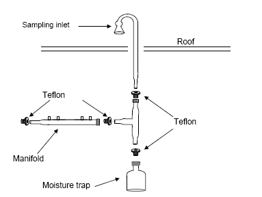
Figure 7. Example sampling manifold.
In designing and installing a sampling manifold, the residence time of the pollutants in the sampling lines should be considered. Although 20-second residence time is the maximum allowed as specified in 40 CFR 58, Appendix E, it is recommended that the residence time within the sampling system be less than 10 seconds. If the volume of the sampling system does not allow this to occur, then a blower motor or other device (such as a vacuum pump) can be used to increase flow rate and decrease the residence time. The residence time for a sample manifold system is determined in the following way. First the total volume of the cane (inlet), manifold, and sample lines must be determined using the following equation:
Equation 1
Volume = Cv + Mv + Lv
where:
Cv = Volume of the sample cane or inlet and extensions
Mv = Volume of the sample manifold and moisture trap
Lv = Volume of the instrument lines from the manifold to the instrument bulkhead
The volume of each component of the sampling system must be measured individually. To measure the volume of the components (assuming they are cylindrical in shape), use the following equation:
Equation 2
V = π * (d / 2)2 * L
where:
V = volume of the component, cm3
π = 3.14
L = Length of the component, cm
d = inside diameter of the component, cm
Once the total volume is determined, divide the total volume by the total sample flow rate of all instruments to calculate the residence time in the inlet. If the residence time is greater than 20 seconds, attach a blower or vacuum pump to increase the flow rate and decrease the residence time.
The gas analyzers should installed in the instrument shelter with short sampling lines connecting each analyzer to separate ports on the manifold. The gas analyzers should be operated based on the manufacturer's recommended procedures and in the configuration in which they were granted Reference Method designation.
With continuous use, the sample inlet and manifold can accumulate deposits of particulate material and other potential contaminants. At least quarterly, the sample inlet and manifold should be cleaned to remove any foreign materials that may have accumulated. The sampling system should be disassembled and the individual components should be cleaned using distilled water (i.e., only high purity distilled water, no organic solvents or soaps) and a long-handled bottle brush. The components should then be rinsed with the distilled water and allowed to dry completely before reassembling.
For these monitoring studies, it is recommended that an Aethelometer be used to measure BC as an indicator for DPM. Since ambient BC particles are typically small (i.e., generally <0.3 µm diameter), the sampling requirements are less stringent than those for the BAM or TEOM. Nonetheless the sampling system used should be designed to minimize particle loss during sampling. The manufacturer recommends that ¼" ID black tubing (i.e., carbon impregnated Teflon) be used for sampling. If possible, the sampling line should run vertically to at least 1 m above the roof of the shelter. The sampling line should include an 180o turn over at the top with a radius of at least 10 cm. The inlet should be protected to avoid rain or insects from entering the sampling line. An inverted funnel with screen mesh covering the face of the funnel can be used on the inlet of the sampling line and should provide sufficient protection from rain and insects.
Once installed, a data disk should be installed, and the Aethalometer can be powered on to start data collection. The flow rate should be verified (5 l/min) to ensure proper operation and the sampling time base for the Aethalometer should be set to 5 minutes. The data disk should be replaced at least monthly.
For these monitoring studies, it is recommended that either a BAM or a TEOM be used as a surrogate for PM2.5. For the installation of either a BAM or TEOM, it is recommended that a straight line-of-sight be available from the inlet on the BAM or TEOM vertically through the roof of the instrument shelter. The BAM or TEOM should be placed on a flat surface beneath the opening in the roof, and a sampling line should be installed based on the manufacturer's recommendations. Typically, sampling kits are available from the vendors to assist in the proper installation of these monitors. A PM2.5 cyclone should be installed on the end of the sampling line to provide appropriate size selectivity.
After installation the BAMs or TEOMs should be configured to operate according to the manufacturer's recommendations and should be set to record data at least hourly. The sampling flow rates should be verified and other manufacturer's recommended diagnostics should be checked to ensure proper operation.
For these monitoring studies, meteorological monitoring should be conducted at one of the monitoring sites located away from the roadway (i.e., between 50 and 150 m, or between 250 and 350 m). The meteorological sensors should be mounted on a meteorological tower which has been installed according to the siting recommendations described in Section 3.2.3. The placement of the meteorological tower should allow for a representative measurement of the ambient conditions at the monitoring site. Furthermore, it is recommended that wind speed and wind direction be measured at each of the monitoring sites.
After installation, the data from the sensors should be captured using a suitable data logger and recorded on at least an hourly basis.
Continuous traffic monitoring must be conducted for each of the monitoring studies completed under this Protocol. It is highly recommended that the monitoring study location be selected in an area where continuous traffic monitoring is already conducted by a State Department of Transportation or other similar agency. If such a location is selected, the hourly traffic data should be provided by the collecting agency to the contractor conducting the monitoring study along with any supporting quality assurance documentation.
If a study location is selected where traffic monitoring is not already conducted, the contractor conducting the study should coordinate with the State Department of Transportation or similar agency to arrange for traffic monitoring equipment to be installed and operated. Traffic monitoring should be conducted as closely to the study location as feasible, and should include the collection of hourly traffic count, vehicle speed, and vehicle classification data if feasible. Upon installation of traffic monitoring equipment, a visual check should be conducted to insure proper operation of the equipment.
As described in Section 2 of this Protocol, the sampling schedule for the TO-11A and TO-15 methods should include 1-in-12 day sampling, with nine (9) 1-hour samples collected during each 24-hour sampling period. The 1-in-12 day sampling schedule should be established to coincide with the schedules followed by state and local air quality agencies in conducting sampling in the USEPA's monitoring networks. Sample collection should be performed such that two of the 1-hour samples are collected during the 3-hour period centered on the morning traffic peak. One of these samples should always be collected on the middle hour of this period representing the peak in the morning traffic. The other of these two samples should be collected alternately either during the hour preceding the peak hour or the hour immediately after the peak hour. The other seven samples should be collected in an equally spaced basis covering the other 21 hours of the sampling day. The schedule for these seven samples should rotate by one-hour for each sampling day such that after three sampling days, all 24 hours of the day have been sampled at least once.
Prior to implementation of a sampling schedule for a given monitoring study, at least one year of historical traffic data should be used to determine the actual peak in the morning traffic pattern for the study location. The MSAT sampling schedule should then be designed around the actual peak traffic data. An example of a potential sampling schedule assuming that the peak hour in the morning traffic occurs between 7:00 and 8:00 a.m. is presented in Section 2.1 of this Protocol.
Analysis of the integrated samples collected during these studies should be analyzed according to established USEPA methods. It is anticipated that the agencies conducting these studies are familiar with these methods, and have in-house laboratories capable of meeting the requirements of these methods, or have contract laboratories that are capable of meeting the requirements of these methods, so only brief discussions of the methods and procedures are presented here. Complete descriptions of the procedures and the requirements of the methods are provided in the references cited.
After sample collection the DNPH cartridges should be sealed in foil pouches and sent to an established analytical laboratory for extraction and analysis. The cartridges should be extracted and analyzed according to the procedures described in Method TO-11A. Additional guidance and recommended practices are presented in the USEPA's Technical Assistance Document for the National Ambient Air Toxics Trends and Assessment Program.10
Upon receipt of the samples, the samples should be placed in a sealable bag with a COC and stored in a refrigerator at <4o C until extraction. Extraction should occur within 2 weeks of the sampling episode. To extract the samples, the cartridges should be removed from the refrigerator and connected to a clean, solid phase extraction manifold. Using a glass or disposable polypropylene syringe attached to the cartridge, 5 ml of acetonitrile (ACN) should be back flushed from the syringe through the cartridge and into a 5-ml volumetric flask. The flask should then be diluted with ACN to the 5-ml mark and transferred to vials for analysis. Samples may be stored under refrigeration (4o C) for up to 30 days, but must be analyzed within 30 days of extraction.
Prior to analysis the HPLC should be calibrated, and method detection limits should be established. When the calibration and method detection limits (MDLs) meet acceptance criteria, the sample vials should be placed into a carousel and loaded onto the instrument. An injection size of sample extract geared to the manufacturer's specifications for the analytical instrument should be performed with an automatic sample injector. A mobile phase gradient of water, ACN and methanol should be used to perform the analytical separation at a flow rate of 1.0 ml/min. Each sequence loaded onto the instrument should start with an ACN instrument blank followed by a QC standard, another ACN instrument blank, the method blanks for each lot of samples to be analyzed followed by the samples. A QC standard should be analyzed every 12 hours to ensure that the instrument is within calibration and the retention times for the compounds have not shifted. The sequence should be completed with a third ACN instrument blank, a final QC standard, and a final ACN instrument blank. For the ACN to meet acceptance criteria, the compound concentrations must be less than or equal to 5 times the method detection limits.
After sample collection the sample canisters should be sent to an established analytical laboratory for analysis. Prior to sample analysis, a system check should be performed on the GC/MS system to ensure proper operation of the instrumentation. After the daily system performance check, calibration laboratory control standard, and daily system blank criteria have met acceptance criteria, the collected samples can be analyzed.
To analyze the samples, the sample canisters are connected to the inlet ports autosampler and the canister valves are opened. A specified volume of a single sample out of a canister along with the specified volume of the bromofluorobenzene (BFB)/internal standard (IS) mixture should be collected and cryogenically trapped using the autosampler preconcentrator while the GC oven is cooled to -50o C. The trapped sample should then be thermally desorbed onto the head of the GC column, at which point the GC should begin the temperature program.
The ISs for each analysis completed in the 24-hour GC/MS analysis period should be compared to those in the most recent calibration. The responses of each IS in the sample should be within ±40% of the mean area response of those of the ISs in the multipoint calibration and the retention time of each IS should be within 0.06 min of the retention time of those in the calibration or the samples should be reanalyzed. If the area response for any IS changes by more than ±40% between the sample and the most recent calibration, the GC/MS system should be inspected for malfunction and corrections made as appropriate. When corrections are made, a calibration check sample must be analyzed to determine whether the multipoint calibration is valid. If acceptance criteria are not met, recalibration is necessary. Reanalysis of samples analyzed while the GC/MS system was malfunctioning is likely to be necessary.
Filters to be used for PM2.5 sampling should be equilibrated in a temperature and humidity controlled laboratory, as specified in the Reference Method, for at least 24 hours prior to both pre-sample and post-sample weighing. Specifically, filters must be conditioned at the same conditions (relative humidity (RH) within ±5 percent RH) before the pre- and postsampling weighings. Mean RH must be held between 30 and 40 percent, with a variability of not more than ±5 percent over 24 hours. However, where it can be shown that the mean ambient RH during sampling is less than 30 percent, conditioning is permissible at a mean RH within ±5 percent RH of the mean ambient RH, but in no case less than 20 percent RH. Mean temperature should be held between 20 and 23o C, with a variability of not more than ±2o C over 24 hours. RH and temperature should be measured and recorded on a continuous basis during filter conditioning (either by a recording hygrothermograph or by electronic instruments).
An appropriate analytical balance is required for the measurement of filter weights. The balance should be calibrated prior to each weighing session, and a variety of calibration and QC checks should be conducted during each weighing session to assure the quality of the gravimetric measurements.

