

Manual on Use of Self-Propelled Modular Transporters to Remove and Replace Bridges
Chapter 6. Contract Documents
Specific plan sheets and specifications that may be included in contract documents for projects that use SPMTs to move bridges are discussed in this chapter. Example plan sheets and specifications are in the appendixes.
In the contract documents, the owner should quantify the penalties for exceeding allowable tolerances or stresses during the moves (for example, geometric tolerances or concrete tensile stresses). The method of measuring the stresses should be based on the system used.
6.1. SPMT Equipment Requirements
Details on SPMT equipment are in the"Description of Equipment" section of Chapter 1. The equipment specification must ensure that the SPMTs will have adequate capability to move the bridge. The four factors that must be considered are stability, spine (frame) strength, hydraulic capacity, and maneuverability. The three factors that determine the required number of SPMT units are stability, spine strength, and hydraulic capacity. When moving bridges, the stability of the SPMTs is not a major concern because multiple units will be used to move a bridge. Therefore, the center of gravity of the bridge is shared among multiple SPMT units, creating a stable system especially when combined with a framing system between the SPMT units at each end of the bridge. As with stability, spine strength is also a minimal concern during transport of a bridge on SPMTs because the travel surface will be relatively level and the load will be evenly distributed across the SPMT platform. The most significant factor in determining the number of SPMT units to use is the hydraulic capacity, which is dictated by the weight and dimensions of the bridge. The fourth factor is maneuverability. SPMTs have the ability to move in any direction for ease of fit-up of the prefabricated bridge systems with the constructed-in-place components.
The contract documents should include an SPMT equipment specification that describes requirements for steering, maximum loads, maximum ground bearing capacity, tolerances for platform flatness, maximum grade that can be traversed, and additional axle-line capacity in case of problems with some of the axles during the move.
Bridge owners who have minimum or no prior experience using SPMTs to move bridges may want to specify in the contract documents that the proposed SPMT operator/subcontractor demonstrate the capacity and capability of its equipment. An owner representative's visit to the operator's yard for a demonstration should verify that the equipment can handle the bridge load within the required tolerances. Failure of the operator to successfully demonstrate the ability of the equipment to adequately perform job requirements would be grounds for canceling a contract.
An example specification for SPMT equipment is in Appendix D.
6.2. Alternative Bridge Span Installation With SPMTs
The owner should design the project for the SPMT driving installation method to ensure the most efficient and cost-effective use of SPMTs to move bridges.
The plan sheets, however, may be developed for a conventional construction method, with additional wording that allows an alternative bridge installation method. This additional wording in combination with significant bonuses/incentives and penalties/disincentives for early and late completion, respectively, and/ or other contracting strategies can be an alternative means of achieving the owner's reduced construction timeline. Wording for an alternative bridge installation method using SPMTs is on the example contractor alternatives plan sheet in Appendix E.
6.3. Alternative Superstructure Design to Reduce Dead Load
The owner could allow the contractor to propose an alternative superstructure design to obtain a more efficient structure by reducing the effect of dead loads. Possible methods the contractor may use to achieve this include the following:
- Shoring the beams during deck construction for composite action so that the entire cross-section resists the deck self-weight. Wording for an alternative composite dead load bridge design to be used in conjunction with SPMTs is on the example contractor alternatives plan sheet in Appendix E. This sheet can be added to the contract documents to provide guidance to the contractor in selecting options for the project.
- Using lightweight concrete for any or all superstructure elements. The following is an example of wording for the lightweight concrete option that can be added to the contractor alternatives plan sheet in Appendix E:
- Lightweight concrete may be used for any or all superstructure elements. Lightweight concrete shall conform to the Standard Specifications.
An example specification for lightweight concrete is in Appendix F.
6.4. Contracting Strategies Using Innovative Contracting Methods
The owner should include innovative contracting methods in the contract documents to give the contractor a financial reason to complete the work as specified and within the owner's reduced construction timeline. The contracting methods must be significant enough to make it worthwhile for the contractors to change their typical operations to achieve the reduced timelines. Examples of innovative contracting methods include incentives/disincentives, bonuses, and lane rentals. Another option could be to allow a short-term detour to eliminate a temporary bridge.
6.4.1. Incentive/Disincentive
Incentive/disincentive (I/D) is an alternative contracting technique that uses incentive monies paid to the contractor for early completion of a project or disincentive monies that are subtracted from the contractor for completing the project later than time allowed by the contract. The I/D technique may be a stand-alone method, or may be applied to other alternative contracting techniques, including no-excuse bonus, A+B (cost-plus-time), liquidated savings, lane rental, design-build, or any combination.
I/Ds are assessed daily and can be used to achieve specific project milestones or to encourage timely completion of the total contract. If intermediate milestones are used, it is recommended that a milestone also be placed at the end of the project to ensure overall reduction of contract time.
Project I/Ds are set by the owner based on daily road-user costs and the construction engineering and inspection (CEI) and administration cost expended by the owner. The incentive payments to the contractor are programmed in the fiscal year in which the incentive payment is expected to be made. Expected payout will occur when the contractor has met the early completion dates noted in the contract.
Two types of I/D contracts are (1) linear, in which the contractor receives or is charged the same daily amount regardless of the number of days completed early or late, and (2) nonlinear (escalating I/D in which the failure-to-work provision applies to the incentive), in which the earlier or later a job is completed, the greater the daily amount paid to or assessed against the contractor.
This concept can be used on a wide variety of project types and is best applied when the owner is willing to pay the contractor to expedite the work to reduce the contract time. It is similar to the A+B (cost-plus-time) concept in that it works well with urban reconstruction and bridge-related projects.
An example incentive/disincentive specification used in conjunction with the contractor alternatives plan sheet in Appendix E is in Appendix G. Examples of other boilerplate incentive/disincentive specifications are in Appendix H.
6.4.2. Bonus
The no-excuse bonus concept is intended to shorten the construction time normally required to perform the work by providing the contractor with a substantial bonus to complete a project within a specified timeframe regardless of any problems or unforeseen condition that might arise. One advantage of this technique is that it motivates efficient construction because it encourages the contractor to keep projects on schedule. Bonuses reward the contractor for early completion, thereby reducing disruption and inconvenience to the traveling public.
Bonuses may be placed on a specific milestone or on a project completion date in the contract specifications for the expressed purpose of completing an element or project within the prescribed time or by a certain date. The bonus can be tied to milestones, a final completion date, or both.
Unforeseen conditions, weather delays, unforeseen site conditions, or other issues that normally extend contract time are not a consideration when granting a bonus. Bonuses are tied to a completion date (timeframe) that is either met or not met. If the bonus date or milestone is not met, the contractor will not receive the bonus. Time extensions are allowed only for catastrophic events, such as a hurricane that directly impacts the contractor's performance.
Utility schedules are crucial when using the no-excuse bonus technique. A contractor may have to accelerate work to get a bonus, requiring the construction engineering and inspection (CEI) parties to also increase staffing or work overtime. The owner may establish contingency funds to cover the increased CEI workload.
Contractors may choose to share bonuses, for example, with utility companies and subcontractors, to get these companies or groups committed to working toward a bonus. Developing and maintaining a realistic schedule is critical for the contractor.
An example bonus specification used in conjunction with the contractor alternatives plan sheet in Appendix E is in Appendix G. Examples of other boilerplate bonus specifications are in Appendix I.
6.4.3. Lane Rental
The lane rental technique is similar to the A+B (cost-plus-time) technique in that the contractors bidding on a lane rental project determine the number of days a lane will be closed during work and use this determination in their bid process. The owner will add the total lane rental bid to the standard bid to decide the award. Awarded contractors using more lane rental days than bid will be charged lane rental fees.
The lane rental fee is based on the estimated cost of delay or inconvenience to the road user during the rental period. The rental fee rates depend on the number and type of lanes closed and can vary for different hours of the day. For example, rush-hour periods from 6:30 to 9 a.m. and 3 to 6 p.m. could have an hourly rental fee of $2,000 for closing one lane, while a lane could be closed at any other time at a rental fee of $500 per hour. The fee is assessed for the time that the contractor occupies or obstructs part of the roadway and is deducted from the monthly progress payments.
The rental fee rates are stated in the bidding proposal and are in dollars per lane per time period. Rental fee rates may be set based on daily, hourly, or fractions-of-an-hour time intervals. The low bid is determined solely on the lowest amount bid for the contract items.
Examples of lane rental specifications are in Appendix J.
6.5. Value Engineering
Value engineering proposals may also be allowed to encourage the contractor to innovate to achieve the reduced construction timelines. Cost savings that result from innovations may be shared by the contractor and the owner. An example value engineering specification is in Appendix K.
6.6. Partnering
The owner should include a formal partnering item in the contract documents to ensure that all parties understand the requirements of the project and to foster relationships that facilitate resolving issues that arise during the project. Discussions should include contingency plans to address potential problems such as insufficient equipment, equipment breakdowns, inclement weather, and inexperienced personnel, as well as logistical issues related to timing of materials, equipment, public notices, and multiple moves within the same window.
An example partnering specification is in Appendix L.
6.7. Traffic Control Plans
Traffic control plans should be consistent with the construction scheme provided in the contract documents. The owner should develop traffic control plans to address detours, rolling roadblocks, crossovers, and closures consistent with traffic control windows defined in the contract.
General notes in the contract documents should accommodate the traffic control requirements for SPMT construction methods. An example list of general notes for traffic control is in Appendix M, with the two modifications for SPMT methods shown in bold.
In many cases one rolling roadblock will be sufficient when using SPMTs to remove or replace a span crossing a highway. The following process has been used for rolling roadblocks on a two-lane highway when spans of a bridge crossing the highway were removed using SPMTs:
- Rolling roadblocks are allowed during nighttime hours only, for example, midnight to 4 a.m.
- A half dozen or so traffic control officers with law enforcement vehicles equipped with flashing blue lights are required. The actual numbers depend on the length of time required to complete the bridge move and the number of upstream on-ramps along the length of the rolling roadblock.
- A traffic control supervisor is stationed at the bridge site continuously throughout the rolling roadblock operations to provide radio communication among the contractor, the engineer, and the law enforcement vehicles.
- Upon notification by the onsite traffic control supervisor, three law enforcement vehicles enter the highway upstream of the bridge construction site. They enter at the posted speed limit.
- Two of the law enforcement vehicles begin flashing their blue lights and immediately form a side-by-side rolling roadblock of both lanes to slow highway traffic to an operating speed of 20 mi/h (32.1 km/h).
- The third law enforcement vehicle is in front of the side-by-side pacing vehicles to trail the last of the traffic ahead of the rolling roadblock operations. It comes to a complete stop with blue lights flashing 500 ft (152.4 m) from the work zone, blocking both highway lanes until the bridge move is completed.
- Upon notification by the onsite traffic control supervisor, the traffic control officers stationed at each of the upstream entrance ramps to the highway activate their vehicles' flashing blue lights and position their vehicles across the ramps to block access to the highway until the rolling roadblock passes.
- Each rolling roadblock operation cycle creates a 20- to 30-minute time period during which the contractor completes the bridge move.
- The contractor is required to clear equipment and workers from the highway lanes both on the ground and overhead when the pace vehicles are within 1 mi (1.6 km) of the bridge site.
- The contractor is required to wait a minimum of 30 minutes from the end of one rolling roadblock operation to the beginning of the next to permit highway traffic to return to normal speed and to allow the three law enforcement vehicles to return to their designated starting point.
An example traffic control plan sheet for rolling roadblocks used for conventional bridge demolition is in Appendix M (see "I-4 Pacing Operation General Notes"). Only one rolling roadblock is required when SPMTs are used to remove an entire span, compared to conventional demolition in which a rolling roadblock is required for each beam removal.
Depending on the details of the project, it may be necessary to temporarily close a highway when SPMTs are used to install a span crossing the highway, rather than use a rolling roadblock to accomplish the installation. An example traffic control plan for a temporary bridge closure when SPMTs were used to replace spans of a bridge crossing a highway is also in Appendix M (see "I-4 Closure Detail").
6.8. Prefabrication Plan
The contractor must submit a signed-and-sealed prefabrication plan that includes the following:
- Geotechnical engineering assessments of ground stability performance of the staging area and SPMT paths of travel, and any ground improvement plan as necessary; provided by the contractor's geotechnical engineer.
- Design and details for temporary supports, including shallow foundations at the staging area, unless the details are provided in the plan sheets; provided by the contractor's geotechnical and structural engineers.
- Settlement evaluation of temporary supports founded on shallow foundations; provided by the contractor's geotechnical engineer.
- Design and details for prefabricated structures at the staging area, including any shoring for composite dead load design, unless the details are provided in the plan sheets; provided by the contractor's structural engineer.
- Settlement monitoring; provided by the contractor's geotechnical engineer.
6.8.1. Temporary Shoring Bents Founded on Shallow Foundations-Differential Settlement
When temporary shoring bents are founded on shallow foundations, differential settlement between temporary shoring bents (see figure 7) can be a major design consideration. Both span geometry and induced loading are affected by differential settlement in both longitudinal and transverse directions, especially if the beams are continuous. Depending on subsurface condition, the design approach may require deep foundations and/or ground improvement strategies.
An example specification for a report on temporary shoring on shallow foundations settlement is in Appendix N.
Figure 7: Differential settlement of temporary shoring bents (courtesy of FDOT)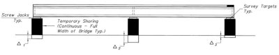
6.9. Movement Plan, Including Incremental Jacking
To remove an existing span, the SPMTs with lifting equipment are driven under the span, the SPMT platforms are extended to lift the span clear of the piers, and the span is driven to the staging area. Using the SPMT hydraulic system and hydraulic jacks, the span load is transferred to cribbing outside the SPMTs' lifting points on each end of the span.
Once the span is set on cribbing, it can be incrementally lowered using the SPMTs. The SPMTs are driven from underneath the span, the lifting equipment on their platforms is restacked at a lower height, and they are driven back under the span.
The span is lifted by the SPMT hydraulic system, the outside cribbing is lowered, and the span is again transferred from the SPMTs to the cribbing. The process is continued until the span is sitting at the contractor's required height on temporary blocking. The cribbing used for the lowering process is part of the equipment provided by the SPMT company. A similar process in the reverse order is used for lifting, moving, and installing a bridge.
Before moves, the contractor must submit a signed-and-sealed movement plan for approval by the owner that includes the following:
- Erection tolerances and provisions for adjustment; provided by the contractor.
- As-built survey of offsite structures (for example, prefabricated superstructure) and onsite structures (for example, cast-in-place substructure) to verify elevation and dimensional differences consistent with design assumptions for fit-up with adequate tolerances; provided by the contractor.
- Dimensions and weights of structures, including face-to-face distances between obstacles (for example, abutments and piers); provided by the contractor's structural engineer. This information will be given to the SPMT company to determine lift point locations for the moves. Note: For the contractor to provide an adequate lifting operation, the bridge designer should calculate and specify an accurate bridge weight.
- Distance from face of obstacle to lift point for each lift point; provided on the SPMT company's shop drawings. These shop drawings will be given to the contractor's structural engineer for analysis of temporary loading effects.
- Analysis of the effects of the temporary lifting and moving loads on the structures, the maximum geometrical tolerances during the move, and strengthening of the structures as needed to avoid excessive stresses or deflections; provided by the contractor's structural engineer. The assessment of maximum geometric tolerances required during the move should avoid excessive stresses on the bridge while permitting an optimum speed of movement.
- Diagram of the path between the staging area and bridge site, showing direction of motion, dimensions, and clearances; provided by the contractor's engineer. Examples of path and motion diagrams are in Appendix O.
- Geotechnical assessment of ground bearing capacity and defined stability performance requirements along the path between the staging area and the bridge site; provided by the contractor's geotechnical engineer. Include provisions for dealing with ground surfaces that are not sufficiently level or where obstacles are encountered. This would involve placement of fill material, ramps, etc., to enable the bridge to be moved in a way that guarantees its stability and avoids the potential for it to experience unacceptable stresses. A combination of compacted ground, temporary pavement, and steel plates may be used to provide the needed bearing capacity to resist the weight of the loaded SPMTs.
- For water moves, an assessment of barge bearing capacity and defined stability performance requirements along the path between the barge loading area and the bridge site; provided by the contractor's engineer.
- Analysis of wind loads on the bridge at its temporary location and during the move.
- SPMT equipment requirements and signed-and-sealed engineering services, including diagrams and process details for lifting, removing, lowering, and installing operations. Geometric controls during the moves and redundancy in the SPMT power system (for example, a backup system) should also be specified.
- Monitoring of geometric distortion during the move; provided by the contractor's structural engineer.
- Contingency planning for incident management if needed (for example, backup equipment in case of mechanical failure, conventional lifting and demolition equipment onsite for timely clearing of the highway, and a highway detour route for extended closure); provided by the contractor.
The movement plan may be used independently for removal of existing bridges, or in combination with the prefabrication plan for removal of the existing bridge followed by installation of the new bridge.
6.10 Contractor Personnel Plan
The contractor is responsible for providing qualified personnel, including subcontractors, to complete the project. The contractor must submit a personnel plan that defines the following responsibilities:
- Signed-and-sealed design and details for temporary supports and prefabricated structures at the staging area, including any shoring, unless the details are provided in the plan sheets; provided by the contractor's structural engineer.
- Signed-and-sealed geotechnical assessment of ground bearing capacity and defined stability performance requirements at the staging area and along the path between the staging area and the bridge site; provided by the contractor's geotechnical engineer.
- For water moves, a signed-and-sealed assessment of barge bearing capacity and defined stability performance requirements along the path between the barge loading area and the bridge site; provided by the contractor's engineer.
- Prefabrication of the structures.
- Erection tolerances and provisions for adjustment; provided by the contractor.
- Before moves, as-built survey of offsite structures (for example, prefabricated superstructure) and onsite structures (for example, cast-in-place substructure) to ensure fit-up with adequate tolerances; provided by the contractor.
- Dimensions and weights of structures, including face-to-face distances between obstacles; provided by the contractor's engineer.
- Distance from face of obstacle to lift point for each lift point; provided by the SPMT company.
- Diagram of the path between staging area and bridge site showing direction of motion, dimensions, and clearances; provided by the contractor's engineer.
- Signed-and-sealed analysis of the effects of the temporary lifting and moving loads on the structures, the maximum geometric tolerances during the move, and strengthening of the structures as needed to avoid excessive stresses or deflections; provided by the contractor's structural engineer.
- Structure lifting, removing, lowering, and installing diagrams and detailed processes, including geometric controls during the moves; provided by the SPMT company.
- Monitoring of geometric distortion during the move; provided by the contractor's structural engineer.
- Contingency planning for incident management; provided by the contractor.
The contractor will provide SPMT company experience and qualifications.
The contractor must clearly define responsibilities for the various construction processes required to remove and install bridges. For example, a deteriorated superstructure that has been removed from its substructure will arrive at the demolition site at its original elevation. The superstructure loads will then be transferred from the SPMTs to temporary supports for demolition.
The first load transfer will be to temporary supports at about the same height as the original substructures. However, the contractor will likely want to lower the superstructure to be closer to the ground for demolition. The SPMTs can then lower the superstructure in increments until it is as low as 5 ft (1.5 m) off the ground. Similarly, the contractor must delineate whose responsibility it will be to lift the new superstructure to its setting height in the staging area before driving it to its final location.
6.11 Submittal Requirements
The following contractor submittals are required:
- Prefabrication plan
- Geotechnical assessment at staging area
- Temporary supports at staging area
- Settlement report for temporary supports founded on shallow foundations
- Prefabricated structures at staging area, including temporary shoring for composite dead load design
- Settlement monitoring
- Movement plan
- Erection tolerance
- As-built survey
- Prefabricated structure dimensions and weights
- Shop drawings with lift point locations and distances from face of obstacle to lift points
- Analysis of temporary loads on structures
- Path and direction of motion
- Geotechnical assessment for move
- Barge stability assessment for move
- Moving equipment and services
- Distortion monitoring during move
- Contingency planning for incident management
- Contractor personnel plan, defining personnel for activities outlined in prefabrication and movement plans