

Precast Bent System for High Seismic Regions: Laboratory Tests of Column-to-Footing Socket Connections
CHAPTER 1. INTRODUCTION
Need for Rapid Construction
Numerous bridges in the United States are either functionally or structurally obsolete.(1) The replacement of these bridges and the construction of new ones will create the need for extensive bridge construction in the near future. If these bridges are built using conventional cast-in-place methods, this construction will exacerbate traffic congestion, which is already a costly problem, especially in urban areas.
New structural systems and construction methods are needed to reduce the time spent on-site. One solution for reducing construction-related delays is to precast structural elements off-site and then assemble them rapidly once they arrive on-site. This approach also has other benefits, such as improved worker safety and construction quality.
However, the use of precast components poses potential problems in seismic regions, where the connections need to accommodate inelastic deformations without loss of strength. To make fabrication and transportation easier, connections are typically made at beam-to-column and column-to-footing interfaces. During an earthquake, these interfaces are also the locations that experience the largest moments and inelastic deformation reversals. Designing connections for both ease of construction and seismic resistance is a daunting challenge.
Precast concrete has been used successfully for bridge substructures in non-seismic regions.(2,3) At the University of Washington, research on accelerated bridge construction (ABC) has focused on the development of precast concrete bridge substructures for seismic regions.(4,5) Hieber et al. performed numerical studies on two types of bridge piers made of precast elements and subjected to ground motions.(6) Wackeret al. developed displacement-based and force-based design procedures for precast systems.(5)
Pang et al. developed a "large-bar" column-to-cap beam connection.(7,8) In this connection, projecting column bars are grouted into ducts inthe cap beam using only a small number of bars to facilitate fit-up on-site. The small number of bars means that each one must be large and, according to typical code provisions, such bars may require development lengths longer than those available in the cap beam. Tests on the pull-out strength of bars grouted in ducts showed that even No. 18 bars can be developed properly within the depth of a typical cap beam.(9,10) Cyclic tests on column-to-beam connections demonstrated that the seismic performance of the large-bar precast subassembly was essentially identical to that of atypical cast-in-place connection.(7) Cohagen et al. tested a similar connection that contained unbonded post-tensioning to improve the re-centering characteristics of the column after the ground motions stops.(11) Those tests showed that the post-tensioned tendon improves the re-centering for peak drifts greater than about 2 percent and offers an opportunity for improving the seismic performance of the bridge bents.
After the column-to-cap beam connection was developed, the research team turned their attention to the column-to-foundation connection. The grouted bar system used for the cap-beam connection can be used there, but it is more difficult to construct, so other concepts were investigated.
Three socket columns in spread footings were tested in two stages in the University of Washington Structural Research Laboratory. Haraldsson constructed two socket specimens.(12) In the first, the reinforcement was detailed to comply with current codes and design practice. In the second, the amount of secondary reinforcement, such as ties, was reduced below the prescriptive minimum, which made the connection easier to construct. Janes tested a third specimen with a thinner footing to better understand the failure behavior and limitations of the connection.(13) This report describes the development, testing and measured performance of these three socket connections.
Socket Connection Concept
The new socket connection concept is shown in figure 1. It is suitable for use with spread footings. The column is precast with a roughened outer surface at the bottom of the column that will be embedded in the cast-in-place footing. Once the footing has been excavated, the column is brought to site, plumbed, leveled, and braced. Top and bottom footing reinforcement is then placed around the column, and the footing is cast. The final step is to connect the column to the cap beam by casting the footing. In comparison with conventional cast-in-place construction, the primary advantage of this system is construction speed; a footing and column can be built in little more time than is needed to cast the footing alone.
Figure 1. Diagram. Rapid construction sequence.
The structural details of the connection were developed at the University of Washington with extensive help from the Washington State Department of Transportation (WSDOT), Berger/ABAM Engineers, Tri-State Construction, Concrete Technology Corporation, and others in the construction industry.
The structural details differ from those of a conventional, cast-in-place system in two ways. First, no bars pass from the footing into the column, so the only resistance to vertical load comes from shear friction across the interface between the precast column and the cast-in-place footing. That interface is intentionally roughened to facilitate this load transfer. Second, the longitudinal column bars are not bent out at the bottom, but instead, they achieve their anchorage by headed anchors. This choice simplifies transportation and handling, and it reduces the hazard posed by protruding bars. The configuration also provides a much simpler and more direct flow of internal forces than is possible with bent-out bars. The transfer of internal forces is illustrated by the strut-and-tie model shown in figure 2. Figure 2a shows that, with conventional bent-out bars, the force in the diagonal strut must be transferred to the vertical bar by bond around the curved region of the bar. That mode of transfer is relatively weak, and a diagonal crack forms in the footing when the bond fails. By contrast, the headed bar shown in figure 2b achieves the load transfer very effectively at a compression-compression-compression (CCC) node.
Figure 2. Diagram. Strut-and-tie models for (a) bent out bars and (b) headed bars.
A preliminary version of the socket connection was deployed as part of a bridge over SR520 in Washington State (see figure 3).
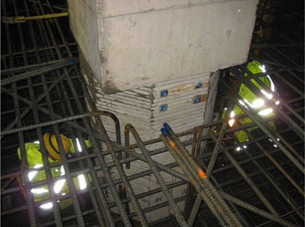
Figure 3. Photo. Earlier form of the socket connection used by the City of Redmond over Washington State SR 520, as originally used.
Objectives and Scope
The goal of the research was to evaluate the seismic and gravity load performance of a socket column-to-foundation connection proposed for a precastbent system with spread footings. The connection concept is to precast the column with an intentionally roughened surface in the region that will be eventually embedded in the cast-in-place footing.
The global question to be resolved is whether the proposed column-to-footing connection can transfer moments from the column to footing under cyclic lateral loading, such as imposed by an earthquake, while resisting large vertical loads that might be caused by a combination of gravity and seismic loadings.
The specific questions to be addressed by this research are primarily structural:
- Does the precast column need to be designed such that the bottom layer of footing reinforcement passes through or under the column? It would be more convenient to place these reinforcing bars outside of the column footprint.
- Is shear friction steel needed between the precast column and the surrounding cast-in-place footing? Such friction steel would typically be placed with form savers where the bars are screwed into the column base, which would slow down construction. If shear friction steel is needed at all, it would be more convenient to place the bars diagonally around the column so that they provide a normal force across the interface between the precast and cast-in-place elements without crossing it.
- If the diagonal bars that trim the space around the column can be used to replace shear-friction steel across the interface, can the amount required be reduced greatly? It would be even more convenient if only a few diagonal bars were needed.
- By using headed bars at the base of the precast column, is it possible to place fewer ties in the footing than are required by current bridge specifications? Placing ties footings can be time-consuming.
Two scaled (42 percent) cantilever test specimens (SF-1 and SF-2) were constructed to answer these questions. One was designed according to current design specifications — the 2009 American Association of State Highway and Transportation Officials (AASHTO) LRFD [Load and Resistance Factor Design] Bridge Design Specifications (referred to hereinafter as AASHTO LRFD), the 2009 AASHTO Guide Specification for LRFD Seismic Bridge Design (AASHTO Seismic Guide Specifications), the 2006 Caltrans Seismic Design Criteria (Caltrans SDC), and the 2008 WSDOT Bridge Design Manual(BDM). (See references 14, 15, 16, and 17.) The other was a simpler, less conservative version that is easier to construct.
As discussed in chapters 4 and 5, the results of these tests showed that the socket connection performed exceptionally well. The damage and deformation were concentrated in the columns, while the footings remained unscathed. The simpler, less conservative specimen (SF-2) performed as well as the specimen designed to the current specifications (SF-1).
Since neither specimen failed in the connection region, further investigation was needed to determine how and when the footing could fail. This could only be done by testing a column with a footing thinner than tested previously, in which the footing depth had been approximately equal to the column diameter. A footing thinner than the column diameter is relatively unusual, but it may be necessary for large columns, in which very deep footings would lead to overheating while the footing concrete cures. A third test was conducted on a column-to-footing specimen with a thin footing, identified as specimen SF-3. The third specimen was designed to address the following questions:
- How far can the footing depth be reduced before failure occurs in the connection zone of the footing rather than the column?
- What is the failure mode for the footing?
- Footing failure by combined punching shear and moment transfer is currently not recognized in the AASHTO LRFD. (Such failure is recognized in American Concrete Institute [ACI] 318 for slabs around columns).(18) Could this type of failure occur in a spread footing?
Chapter 2 describes the development of the test specimens and describes the proposed connection in detail. Chapter 3 describes the experimental program. The subsequent two chapters evaluate the performance of the proposed connection by considering the damage progression (chapter 4) and measured response (chapter 5). Chapter 6 provides an analysis of test results, and finally, chapter 7 summarizes the report findings and gives recommendations for future research.