

Precast Bent System for High Seismic Regions: Laboratory Tests of Column-to-Footing Socket Connections
APPENDIX B: MATERIAL TESTS
Concrete Strength
The design compressive strength of both the precast columns and the cast-in-place spread footings was 4,000 psi. The coarse aggregate used was 3/8-inches, and the specified slump was 5 inches. Air-entrainment was used in the precast columns to simulate practice conditions in the Pacific Northwest. The cast-in-place footings were not intended to be air-entrained, but it was necessary since the fabricator was not able to provide a batch without air-entrainment for a 3/8-inch aggregate mix. Bigger aggregates increase shear strength, so the column mix was used for the footings as well.
For every casting operation the slump and air content were measured. The slump test was conducted according to ASTM C143, and the air content according to ASTM C231. The results of those measurements are summarized in table 25.
| Specimen | Batch | Slump (in.) | Air Content (percent) |
|---|---|---|---|
| SF-1/SF-2 | Column | 5.4 | 7 |
| Footing | 5 | 5.7 | |
| SF-3 | Column | N/A | N/A |
| Footing | N/A | N/A |
The precast column segments for specimen SF-1 and SF-2 were constructed by a contractor at a construction site in the City of Redmond. The segments cured outdoors for the first 16 days before they were transferred into the University of Washington Structural Laboratory, where footings were fabricated. In contrast to specimen SF-1 and SF-2, specimen SF-3 was constructed entirely at the Structural Laboratory.
For all specimens, cylinders for both batches (column and footing) were fabricated according to ASTM C31 (4-inch by 8-inch cylinders for SF-1 and SF-2, 6-inch by 12-inch cylinders for SF-3). For specimens SF-1 and SF-2, the cylinders were kept adjacent to the specimens to capture their compressive strength. Concrete cylinders for specimen SF-3 were stored in a fog room. The number of column cylinders was limited, so strength tests at 7 days and 14 days were skipped for specimen SF-1 and SF-2. Split cylinder tests were conducted according to ASTM C496. Test results are presented in tables 26 through 28.
| Specimen | Cylinder Sample | Test Cylinder No. | 7 Day (psi) | 14 Day (psi) | 28 Day (psi) |
|---|---|---|---|---|---|
| SF-1/SF-2 | Column | 1 | N/A | N/A | 4,791 |
| 2 | N/A | N/A | 4,717 | ||
| Footing | 1 | N/A | N/A | 6,077 | |
| 2 | N/A | N/A | 5,998 | ||
| SF-3 | Column | 1 | 5,282 | 5,920 | 6,384 |
| 2 | 5,615 | 5,836 | 7,088 | ||
| Footing | 1 | 5,069 | 5,609 | 6,212 | |
| 2 | 5,252 | 5,823 | 6,854 |
| Specimen | Cylinder Sample | Test Cylinder No. | Days | Day of Test (psi) |
|---|---|---|---|---|
| SF-1 | Column | 1 | 113 | 4,660 |
| 2 | 5,330 | |||
| Footing | 1 | 91 | 6,680 | |
| 2 | 6,330 | |||
| SF-2 | Column | 1 | 129 | 5,401 |
| 2 | 5,591 | |||
| Footing | 1 | 107 | 6,723 | |
| 2 | 6,805 | |||
| SF-3 | Column | 1 | 120 | 8,190 |
| 2 | 7,679 | |||
| Footing | 1 | 113 | 7,693 | |
| 2 | 8,117 |
| Specimen | Cylinder Sample | Test Cylinder No. | Days | Day of Test (psi) |
|---|---|---|---|---|
| SF-1 | Column | 1 | 113 | 511 |
| 2 | - | |||
| Footing | 1 | 91 | 596 | |
| 2 | - | |||
| SF-2 | Column | 1 | 129 | 613 |
| 2 | - | |||
| Footing | 1 | 107 | 653 | |
| 2 | - | |||
| SF-3 | Column | 1 | 120 | 718 |
| 2 | 644 | |||
| Footing | 1 | 113 | 596 | |
| 2 | 599 |
1 Two 28th day split cylinder tests (No. 1: 553 psi, No. 2: 592 psi) were performed on footing cylinders for specimens SF-1 and SF-2.
Grout Strength
The precast columns for specimens SF-1 and SF-2 were segmentally constructed. In both specimens, the splice was located 20 inches above the spread footing. Bars protruded up from the base segment of the column to be spliced into ducts in the top segment. The grouting operation for the specimens was performed in two steps. First, the precast column segments were leveled and shimmed. The interface between the segments was grouted. Once the interface grout had hardened, the corrugated metal ducts were injected with grout to anchor the bars in them.
A commercially available packaged grout (1118 Grout-Unsanded Silicon Fume Grout) was used for both grouting operations. The grout is designed to be used as a flowable grout. The procedure was to mix together the dry grout ingredients and clean water at a temperature between 50 and 64 degrees Fahrenheit, to mix continuously for at least 5 minutes, and then place the grout using a hand pump and plastic tubes. In each grouting operation, four standard 2-inch testing cubes were made, and two cubes were tested according to ASTM C109 on each subassembly´s test day. Table 29 summarizes the results of the grout on test day. Test cubes for the ducts in specimen SF-2 measured lower strength because they were accidently mishandled.
| Specimen | Cube Sample | Test Cylinder No. | Days | Day of Test (psi) |
|---|---|---|---|---|
| SF-1 | Interface | 1 | 60 | 13,100 |
| 2 | 13,050 | |||
| Ducts | 1 | 56 | 12,850 | |
| 2 | 12,150 | |||
| SF-2 | Interface | 1 | 73 | 12,700 |
| 2 | 13,350 | |||
| Ducts | 1 | 77 | 9,950 | |
| 2 | 12,400 |
Reinforcement
Prototype design reinforcement conformed to ASTM Standard A706. All main reinforcement steel was scaled down appropriately (42 percent). Scaling down the transverse reinforcement in the column and the ties in the spread footing was difficult (No. 5) since the smallest reinforcement available conforming to A706 is No. 3 bars. Smooth wires conforming to ASTM A82 were used instead, with 3-gauge wire (0.244-inch diameter) for the spiral and 2-gauge wire (0.263-inch diameter) for both the footing ties. A laser extensometer with 1-inch gauge length was used to calculate strain. In contrast to specimens SF-1 and SF-2, the tension tests for specimen SF-3 were performed using an 8-inch gauge length extensometer. The coupons were loaded until the steel began to yield and the load dropped. The extensometer was then removed to prevent damage to the equipment. The coupon was then loaded till failure, after which the length was measured to obtain a strain at failure. Therefore, the line from yield to failure shown in the plots does not represent an actual measure response, but rather is there to provide a visual connection between the yield and failure point.
Table 30 shows the measured mild reinforcement properties, and the results from the tension tests are presented in figures 110 through 120. ASTM A82 requires 70 ksi minimum yield strength and a minimum tensile strength of 80 ksi. The test results for the spirals and the stirrups showed lower values because the wires were supplied bent into a coil and needed to be straightened out before testing. To be consistent with previous tests, the yield strain was taken as 0.35 percent strain to avoid any subjectivity into the test results.
For each bar size, the yield strain was calculated using the equation in figure 109, where E = 29,000 ksi.
Figure 109. Equation. Calculating yield strain.
| Bar | Anominal (in2) | Specimens SF-1 and SF-2 | Specimen SF-3 | ||
|---|---|---|---|---|---|
| fy (ksi) | fu (ksi) | ||||
| No. 7 | 0.60 | N/A | N/A | 66.2 | 95 |
| No. 6 | 0.44 | 61.6 | 86.1 | 59.2 | 88.2 |
| No. 5 | 0.31 | 63.3 | 91.4 | 66.1 | 108 |
| No. 4 | 0.20 | 63.7 | 90.4 | 65.9 | 91.6 |
| No. 3 | 0.11 | 65.2 | 94.5 | 62.4 | 99.9 |
| 2-gauge wire | 0.054 | 63.4 | 86.4 | N/A | N/A |
| 3-gauge wire | 0.047 | 59.4 | 73.6 | N/A | N/A |
Stress-Strain Plots for Specimens SF-1 and SF-2
Figure 110. Graph. Specimens SF-1/SF-2 stress-strain curves for No. 6 bars.
Figure 111. Graph. Specimens SF-1/SF-2 stress-strain curve for No. 5 bar.
Figure 112. Graph. Specimens SF-1/SF-2 stress-strain curve for No. 4 bar.
Figure 113. Graph. Specimens SF-1/SF-2 stress-strain curves for No. 3 bar.
Figure 114. Graph. Specimens SF-1/SF-2 stress-strain curves for stirrups (2-gauge wire).
Figure 115. Graph. Specimens SF-1/SF-2 stress-strain curves for spiral reinforcement (3-gauge wire).
Stress-Strain Plots for Specimen SF-3
Figure 116. Graph. Specimen SF-3 stress-strain curve for No. 7 bar.
Figure 117. Graph. Specimen SF-3 stress-strain curve for No. 6 bar.
Figure 118. Graph. Specimen SF-3 stress-strain curve for No. 5 bar.
Figure 119. Graph. Specimen SF-3 stress-strain curve for No. 4 bar.
Figure 120. Graph. Specimen SF-3 stress-strain curve for No. 3 bar.
Corrugated Metal Ducts
The corrugated post-tensioning ducts used to splice together the column segments in specimens SF-1 and SF-2 had an inside diameter of 1.67 inches. They were 26-gauge thick and conformed to ASTM A653. See figure 121.
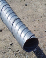
Figure 121. Photo. Corrugated metal duct used in test specimens.