

Precast Bent System for High Seismic Regions: Laboratory Tests of Column-to-Footing Socket Connections
APPENDIX D: CONSTRUCTION SEQUENCE
All specimens were constructed in the same manner. Specimen SF-3 differed from specimens SF-1 and SF-2 because it had a shallower spread footing and did not include a column splice. The basic construction sequence was to precast the column, place it in the prepared footing, and then pour the footing around the column. The construction sequence and details are provided in this appendix.
Specimen Construction Sequence
The column was constructed using a circular, Sonotube form for the portion of the column above the footing. This form was connected to a custom-built octagonal piece which had a roughened surface. The roughened surface was formed by nailing on wooden strips. After the cage was placed in the formwork, PVC pipes to allow for the actuator bolts and the curvature rods were inserted into the formwork. The PVC pipe and curvature rods (for mounting instruments) also served to secure the cage in the formwork. The precast column segments for specimens SF-1 and SF-2 were fabricated in the City of Redmond. Specimen SF-3 was fabricated entirely in the Structural Laboratory at the University of Washington. Figures 155 through 158 show the column fabrication and formwork.
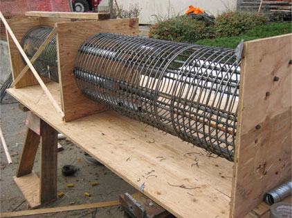
Figure 155. Photo. Column segments for specimens SF-1 and SF-2 were match-tied at a bridge construction site in the City of Redmond.
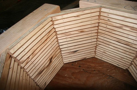
Figure 156. Photo. Roughened surface of octagonal, bottom portion of column.
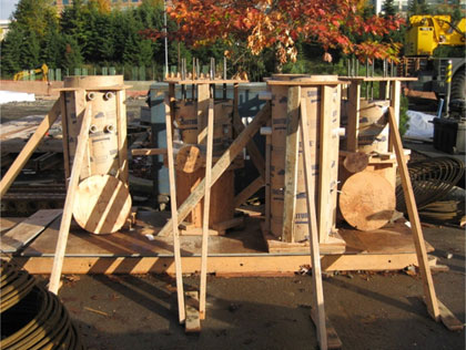
Figure 157. Photo. Specimens SF-1 and SF-2, column segments formed and ready to be cast.
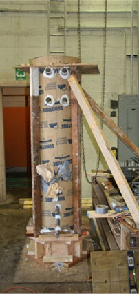
Figure 158. Photo. Specimen SF-3, column formed and ready to be cast.
The column segments for specimens SF-1 and SF-2 were low enough to be cast directly from a concrete truck. The precast column for specimen SF-3 was twice as high as each segment of specimens SF-1 and SF-2, and it was located inside the Structural Laboratory. Because of space limitations, a clamshell bucket was used to deposit the concrete. In all specimens, concrete was poured in lifts of approximately 2 to 3 feet each. To avoid segregation problems for specimen SF-3, a tremie tube was connected to the bucket to deliver the concrete to the bottom of the form.
The footing formwork for specimens SF-1 and SF-2 was constructed in the Structural Laboratory while the column segments cured outside. In both specimens, the bottom mat was placed in the footing forms, the column base segment was lifted in and braced, and the top mat and the ties were placed. Specimen SF-3 had a thin footing, so all of these steps were completed before the column was inserted into the forms. In all specimens, PVC pipes were included to allow for hold-down rods, and lifting loops were placed to maneuver the specimen. Finally, the footing was cast. Figures 159 to 161 show the footing formwork and reinforcement, and figure 162 shows the footing cast with concrete.
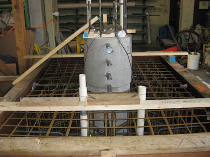
Figure 159. Photo. Specimen SF-1 footing ready to be cast.
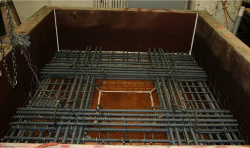
Figure 160. Photo. Specimen SF-3 footing formwork and reinforcement.
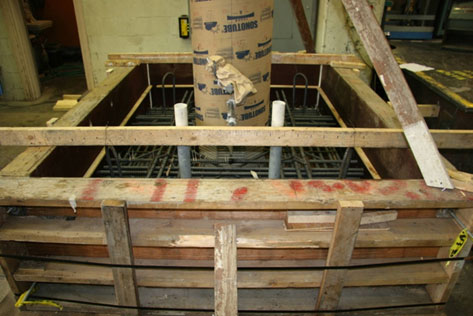
Figure 161. Photo. Specimen SF-3 column inserted into footing that is ready to cast.
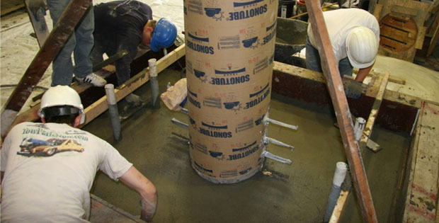
Figure 162. Photo. Specimen SF-3: finishing the footing surface.