Precast Bent System for High Seismic Regions: Laboratory Tests of Column-to-Footing Socket Connections
APPENDIX A: SPECIMEN CONSTRUCTION DRAWINGS
Specimen SF-1
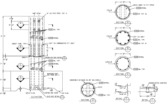
Figure 96. Diagram. Specimen SF-1 column elevation and sections.
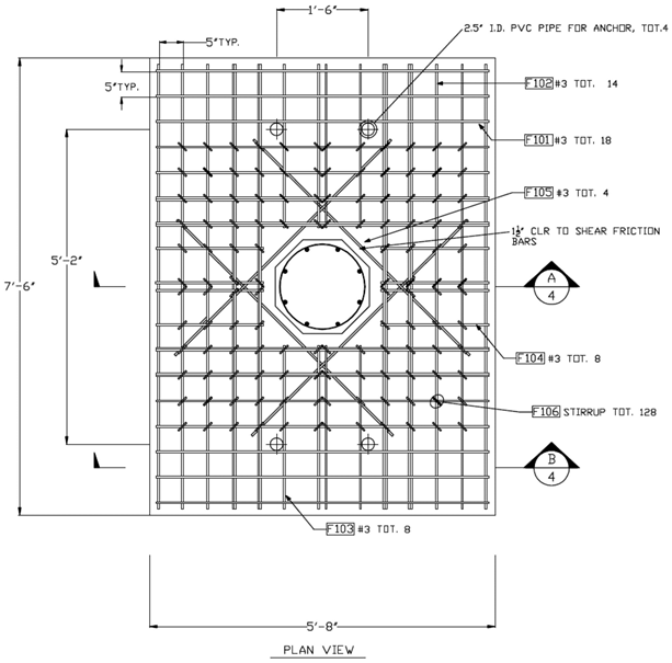
Figure 97. Diagram. Specimen SF-1 top mat plan view.
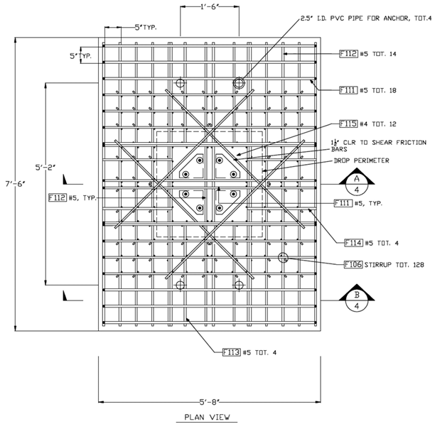
Figure 98. Diagram. Specimen SF-1 bottom mat plan view.
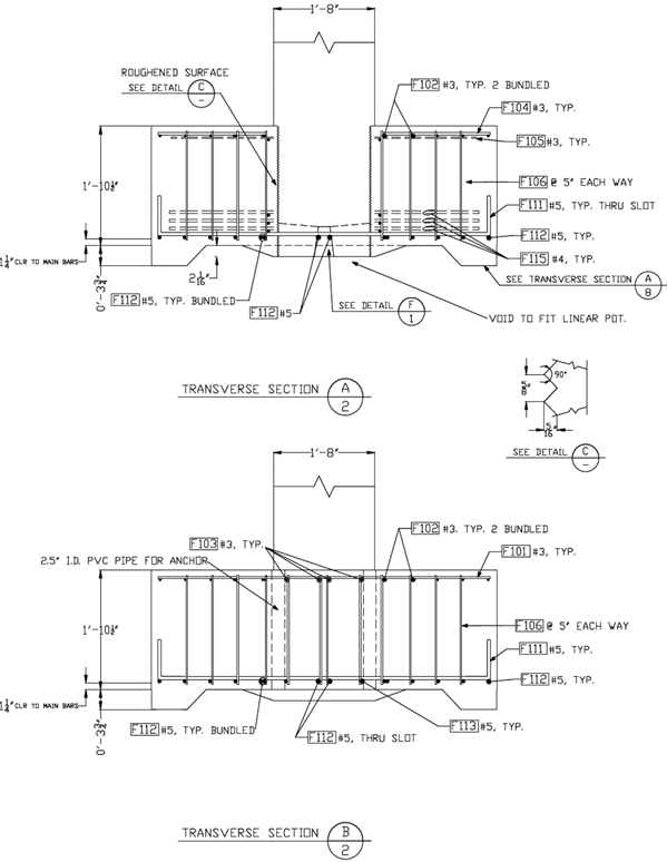
Figure 99. Diagram. Specimen SF-1 sections.
Specimen SF-2
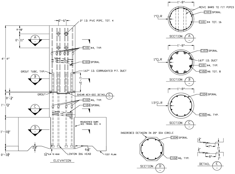
Figure 100. Diagram. Specimen SF-2 column elevation and sections.
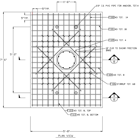
Figure 101. Diagram. Specimen SF-2 top mat plan view.
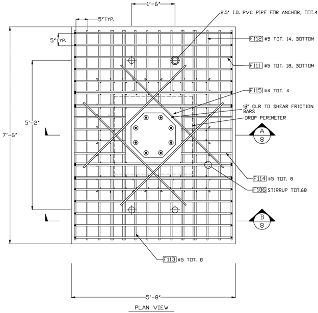
Figure 102. Diagram. Specimen SF-2 bottom mat plan view.
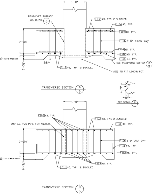
Figure 103. Diagram. Specimen SF-2 sections.
Specimen SF-3
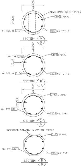
Figure 104. Diagram. Specimen SF-3 column sections.
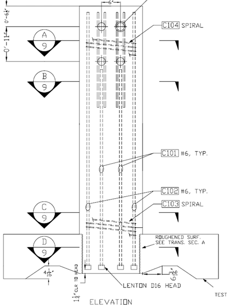
Figure 105. Diagram. Specimen SF-3 column elevation.
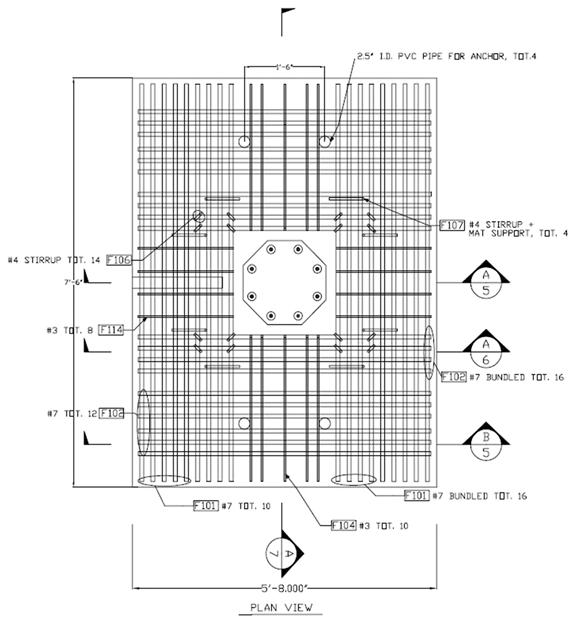
Figure 106. Diagram. Specimen SF-3 bottom mat plan view.
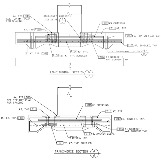
Figure 107. Diagram. Specimen SF-3 footing sections A7 and A6.
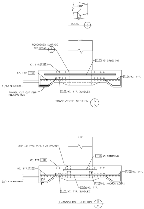
Figure 108. Diagram. Specimen SF-3 footing sections A5 and B5.

