U.S. Department of Transportation
Federal Highway Administration
1200 New Jersey Avenue, SE
Washington, DC 20590
202-366-4000
This case study discusses some of the equipment calibration procedures, current practices, and new procedures used by the Statewide Travel and Collision Data Office (STCDO) at the Washington State Department of Transportation (WSDOT). WSDOT conducts an extensive traffic data collection program to gather information on usage of the approximately 7,060 miles of roadway composing the State highway system. The purpose of this program is to develop transportation data that will enable the department to construct, operate, and maintain the most efficient and cost-effective transportation system possible given resource constraints.
STCDO is responsible for collecting, processing, analyzing, and reporting historical/archived traffic data for the State highway system and does not contract out for any services. The five major sections in STCDO that perform this work are Electronics, Short Duration Traffic Count Field Operations, Automated Data Collection, Short Duration Traffic Count Processing, and Travel Analysis. Each of these sections perform quality assurance (QA) and quality controls (QC) using their own procedures from site evaluation prior to collection of the traffic data to scrutinize the collected data for accuracy and consistency prior to dissemination to the customers. The following paragraphs provide an overview of the procedures, experiences, and lessons learned over the history of WSDOT’s traffic data program. The data collected is made available to WSDOT’s customers through a Traffic Datamart that includes traffic volume, classification, speed, and weight information.
The following paragraphs describe the procedures used for equipment validation, field and office testing, and the reporting method used for WIM sites.
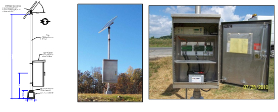
Permanent Count Equipment – WSDOT Statewide Travel and Collision Data Office (STCDO) field technicians check weigh-in-motion (WIM) and classification counters for accuracy of axle counts, vehicle speeds and lengths, weights for WIM computers, and basic total counts of vehicles. Loop and sensor sensitivity is checked for each site. Observations are recorded for each detector source. If the loop or axle sensor is found to be over or under counting, adjustments can be made that raise or lower the sensitivity. Loop size and spacing are based on actual measurements taken at each site that are then entered into the counter. Vehicle speeds are checked against a calibrated radar gun. Vehicle classification accuracy is visually checked against the data displayed in the permanent traffic recorder for the FHWA 13 vehicle category classification system if based on axles or on a length-based classification system developed based on a research project completed in the 1990s. Any counter that does not pass system checks is removed from service, repaired and then bench-tested before placing back into service. When performing WIM calibration, a class 9 truck is used that has been taken to a certified set of static scales and the weight of each axle is determined. All axle weights are recorded and vehicle axle spacing and overall length is measured. The truck then passes over the WIM sensors 10 plus rounds and calibration adjustments are completed to bring the WIM site accuracy to accurate levels. Weight tolerances are within 5% to 7% of static weight, vehicle lengths to one foot, and axle spacings within 5 inches. Calibrations are based on steering axle weight of a class 9 truck. Weight checks are also tested at different vehicle speeds to achieve quality weights for varying traffic conditions
Pneumatic or Short Count Counters – Any new equipment is first tested on a highway using real traffic flow where the traffic volume is high enough to collect an adequate sample of at least 200 vehicles per hour and classification of at least 20 trucks per hour. The vehicle counts and classification results from the new counter are compared to a manual count performed by a short count technician. If the counter passes the manual test comparison, the equipment is put into regular service.
Each time a portable counter is set, the counter should be checked for proper operations and accuracy. Checks are accomplished by visual comparison and hand tally of vehicles for 5 minutes or 50 vehicles for volume or class. Results of both comparisons are recorded on the traffic counter field sheet. If the traffic counter is not functioning properly, air tubes are checked and replaced or the traffic counter is replaced. Equipment malfunctions are recorded on the traffic counter field sheet. The supervisor is notified of traffic counter malfunctions and it is turned over to the Electronic Section for further testing and/or repair.
Data collection counters for permanent and temporary count sites can be checked for operation with testing equipment available in the electronics shop. A loop/piezo simulation device was designed and built by the electronics shop. Any newly purchased equipment or permanent counter brought back to the shop for repairs can be tested for loop and piezo activations.
Short count tube counters can also be tested in the office. Traffic counters can be connected to an air pulse simulator that runs through a sequence of classification schemes.
A sheet 16 calibration report is completed for WIM calibration. This report is sent to LTPP for verification of calibration. All other QC reports for calibration and data accuracy are retained in-house.
Winter weather can inhibit regular site preventative measures (PM) in many areas of Washington State. The regular construction and repair season can leave little time for site preventative measures. Many permanent count sites do not get a regular PM check until a site visit is needed for some type of troubleshooting and repair.
Use of a known weight truck for WIM calibration can be costly. Budget reductions have limited the use of this resource.
Challenges for short count are areas where tubes can no longer be set to collect the data due to traffic volumes or roadway geometrics. In this case, an alternative method is required to obtain the data
This case study examines the traffic data collection equipment calibration and validation procedures used by the New York State Department of Transportation (NYSDOT), and presents current practices and lessons learned, which can benefit other State DOT traffic monitoring programs. NYSDOT is responsible for managing a State and local highway system of more than 113,000 highway miles and more than 17,400 bridges. The responsibility for collecting traffic data on this extensive system relies on a comprehensive network of data collection equipment for volume, classification, and weight data. Procedures are in place to ensure that the processing and reporting of this data results in delivering the highest quality traffic data possible.
This case study focuses on the equipment used to collect traffic data for the highway system. The responsibility for collecting, processing, and disseminating the traffic data at NYSDOT resides with the Highway Data Services Bureau. Managing the collection of traffic data for such an extensive network is challenging, however, NYSDOT uses a variety of counters and classifiers with over 170+ continuous count stations used to collect the volume data and a network of 24 sites for collecting Weigh-In-Motion (WIM) data.
The New York State continuous count stations vary in volume size (ranging from low to high volume), differing geographic location and areas of population density, and facility type (functional classification of the roadway). The individual continuous count sites are also subject to occasional equipment failure, removal, and addition of new sites. The methods used to field check and maintain the data collection sites are the subject of this case study. As a frame of reference, Figure F-1 provides an illustration of the New York State Thruway network and the continuous count sites.
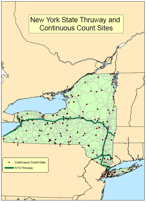
Source: New York State Department of Transportation.
In addition to the continuous count stations used to collect volume data, a series of WIM sites located throughout the state are used to collect weight data. Information about establishing the sites and calibrating the equipment used is discussed in more detail in the next section. At a minimum, NYSDOT uses the following guidance in establishing their WIM sites. Each site should exhibit the following characteristics:
This section presents current practices pertaining to equipment validation and testing
In order to maintain quality data collection, the NYSDOT traffic monitoring field staff inspects each traffic data collection site annually. During these inspections, the physical condition of the site is recorded on a site-specific spreadsheet by field staff. This includes the counters, communications devices, cabinets, solar panels, pavement conditions, pull boxes, sensors, and cabinet wiring. Once all components of the site are deemed to be in good condition the communication is checked to be sure remote access and data retrieval is possible. Then the counter is checked to make sure that data is collecting correctly. This typically involves watching sensor activations in real time, and also watching vehicle records in real time. How in-depth the check is depends upon the level of data a site is collecting. For volume only data, typically assuring that the loops are activating and each vehicle is counted as one vehicle is sufficient.
Sites that collect speed data are checked for accuracy by a radar gun. Sites that collect classification data are checked to make sure there are no missing or extra axles on the vehicles. On a normal site inspection, data validation may range from watching as few as ten vehicles to watching a few hundred vehicles. At the very least, the test will last until all lanes have been validated. The data is also validated in this manner any time a technician is on site. In some cases, a polling technician may log into a site without a field technician on site. In these cases, less information is available; for example there is no way to tell that a recorded class 8 was really a class 9 that missed a tandem axle.
NYSDOT uses a TC/C-540 counter with a WIM board to collect WIM data. As such, the sites are auto-calibrated by adjusting the Front Axle Weight of Class F9s to be between 9-12KIPS. Depending upon the volume of trucks at the site, the calibration may be set to use the average front axle weight from a sample of anywhere from 10-30 trucks. WIM sites calibrations are monitored through a variety of charts and checks. The checks listed above provide minimal detail, and usually lead to resetting the auto-calibration factors to one.
A FAW/GVW (Front Axle Weight/Gross Vehicle Weight) chart was developed that shows the Class 9s for a site by direction, and is also available in a PDF format to be used as a flip book to see where calibration has drifted and what data needs to be removed. Figure F-2 illustrates an example of the FAW/GVW chart.
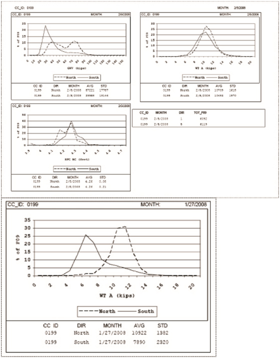
Sources: New York State Department of Transportation.
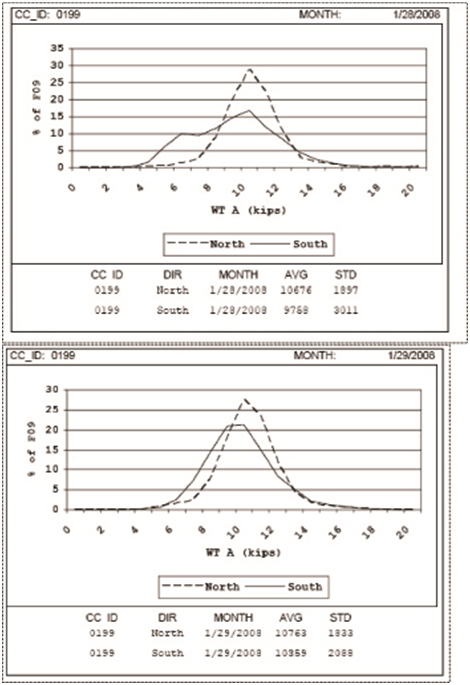
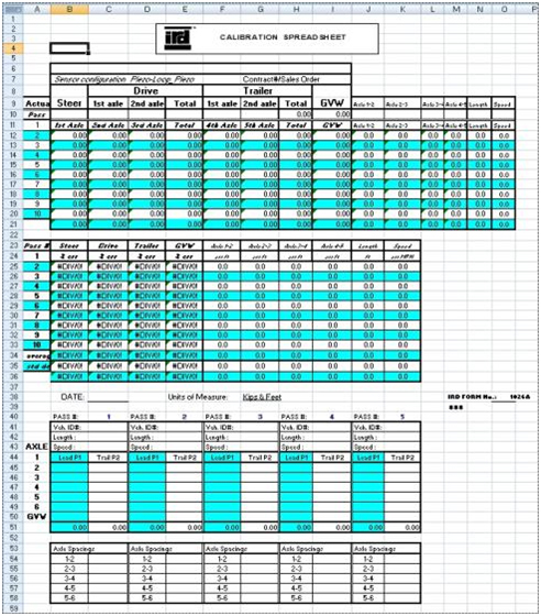
The field crews also spot check WIM calibration by running a class-9 lowboy carrying a loaded dump truck over the sensors. Prior to testing, the lowboy is weighed and axle spacings and overall length are measured and recorded. Then the truck performs ten passes over each WIM enabled lane. The results are recorded on the “WIM Field worksheet.tif” (see Figure F-3) and then entered into the “WIMCalibration.xls” file (see Figure F-4) to monitor the performance. If the performance is outside of acceptable range, the maintenance contractor is notified.
Source: New York State Department of Transportation.
Source: New York State Department of Transportation
In the absence of having someone watch the traffic, the office is limited to checking that sensors are activating in sequence by lane and that speeds seem to be reasonable for the site. When available, the speeds can be validated by watching the drive axle spacing on Class 9s, if they are within the range of 4.2 to 4.4 feet. Under these circumstances, the site would be considered acceptable. Traffic can also be remotely monitored to make sure that there is an acceptable amount of sensor misses at the site. The amount of information available also varies based on the equipment used. NYSDOT uses a variety of counters and classifiers to collect their volume and classification data.
Several remote checks are performed using automated procedures. NYSDOT Traffic Monitoring polling technicians review data from continuous sites at many levels. The data starts on a counter and ends up in an Oracle database with many steps along the way.
The first step is downloading the data. This is done using the Autopoll function of a few different programs. From most sites, the data is downloaded once a week. The most basic high level checks include the following:
Once these questions have been answered, the data collected is stored in a holding database. This database runs a number of automated quality checks on the data; some checks apply to volume, class, or WIM data. Higher levels of data have more checks that apply.
Volume data checks include the following
Classification data checks include the following:
WIM data checks include the following:
Once data has been collected into the holding database for an entire month, it is extracted into the NYSDOT format as defined by NYSDOT EB 11-030 Traffic Monitoring Standards for Contractual Agreements. This format allows the data to be processed through NYSDOT’s Traffic Count Editor (TCE) program. This program displays volume, classification, and speed data in various charts and tables. It can allow a processor to find errors in the data that were not apparent from the initial automated checks. TCE also allows the technician to remove data that is identified as ‘no good’. The files are then edited and saved for import into the final Oracle database. On import, the data is checked to ensure it is not duplicate data.
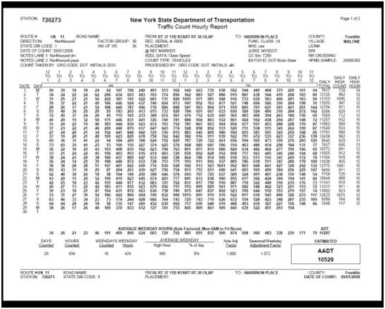
After completion of checks for duplicate data, the data is now ready for reporting. The standard FHWA Volume and Classification records are created and submitted to FHWA and an Hourly Volume report and Monthly Class and Speed summaries are created and posted to the NYSDOT Traffic Data Viewer available at https://www.dot.ny.gov/tdv. Raw data files for volume data are created and posted on the NYSDOT website:
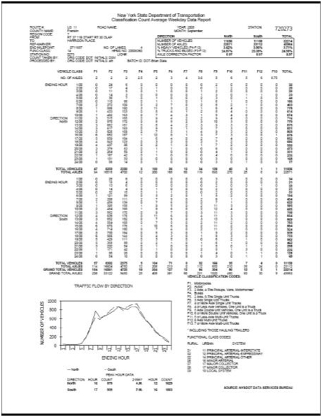
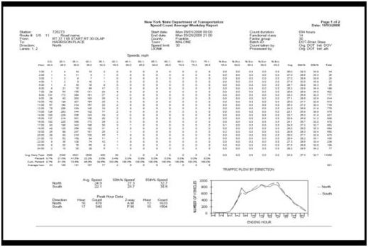
https://www.dot.ny.gov/divisions/engineering/technical-services/highway-data-services/hdsb. The standard reports display data directionally. An example of this type of report is shown in Figure F-5. Figure F-6 includes screen images of volume, speed, and classification reports.
Source: New York State Department of Transportation.
Source: New York State Department of Transportation.
Source: New York State Department of Transportation.
In addition to the standard reports, all data is available at the interval level by lane. NYSDOT provides this data in report and comma separated variable (CSV) formats on request. The next section discusses the challenges associated with using the current practices.
Communication with sites was a challenge for NYSDOT. Without communication, it takes longer to obtain data, identify errors, and correct problems. Over the last two years, NYSDOT has converted approximately 75% of continuous sites to IP connections over cellular networks. This allows for faster downloading and more reliable connections compared to landline and dial-up cellular service.
Another challenge is the conversion of data from counter to holding database then editing files and processing them to the final database. This process can be lengthy and without sufficient staff can take months to cleanse and publish the data. NYSDOT is currently going into production with TRADAS; this should allow data to be downloaded from the counters and placed directly into the final database. This process will not eliminate any of the QC checks and will add some that are not currently used by NYSDOT. Once this is fully implemented data publishing will be timelier.
One advantage NYSDOT has when validating traffic counts is the Traffic Count Editor (TCE) software application. This software displays all short term and continuous traffic counts in side-by-side graphical and tabular displays. The user can choose the aggregation level of the charts and the type of charts. This visual display makes apparent errors that would not be found by automated means. The software was originally designed for short term counts, thus necessitating continuous counts to be loaded one month at a time to maintain performance. TCE is owned by NYSDOT and can be provided to other States, and modified by the developer at a modest cost to suit their individual needs.
NYSDOT also tests counters against existing permanent sites. Currently the favored test site used is a six-lane expressway with an AADT of more than 160,000. This site allows NYSDOT to see the performance of new devices in heavy volume, at both high and low speeds, and in free flow and congested conditions.
NYSDOT requires their traffic count contractors to test annually all portable traffic counters intended for use on contracts, prior to the count season, to ensure that the contractor’s count deviation does not exceed 2%. The following instructions illustrate the required procedure for testing.
There are a number of areas that NYSDOT Traffic Monitoring has identified for improvement. One of these issues includes the time lag between collecting and publishing data, which will be resolved upon the implementation of TRADAS.
Reporting of data will be improved by reducing the number of steps between collection and publication. Currently, continuous count data is converted multiple times and edited manually before being published. Upon full implementation of TRADAS, continuous counts will be converted one time or perhaps not at all, and some data edits will be tied to automated validity parameters.
The implementation of TRADAS will also allow the NYSDOT Traffic Monitoring staff to pursue quality checks that are not currently being used, such as:
The State of Alaska DOT&PF has the responsibility for analyzing and reporting traffic data on the approximately 16,000 centerline miles of public roads in the state. The primary responsibility for traffic data collection is held by the State DOT, although about 5% of traffic count data comes from local governments. The data collection staff in each DOT region (Northern, Central, and Southeast) is responsible for the short term and continuous vehicle volume, classification, speed, and intersection turning movement count programs. The continuous count program in Alaska consists of about 100 stations distributed throughout the State, of which half are vehicle classification sites. Approximately 2,000 short-term counts are conducted annually.
Traffic volume reports are published by each region annually and are located on the department website, and include continuous data, classification data, and VMT tables. The department does not currently have a bicycle and pedestrian data collection program, although some bicycle and pedestrian data is being collected at a project specific level. The weight data collection program is handled in the headquarters office that also compiles the completed ADT and AADT data and submits it to FHWA for the monthly travel volume trends report and annual HPMS report.
In the process of installing new permanent traffic recorders or maintaining an existing site, traffic sensors, primarily inductive loops and piezoelectric axle sensors, are tested with the appropriate instruments before installation to ensure functionality. A member of the traffic monitoring program staff is on site to oversee the installation and offer any assistance that may be required during the construction process. Once installed, the site undergoes a formal acceptance testing procedure to ensure the proper calibration of the traffic counter and performance of the newly installed sensors. The test consists of 10 passes of three differently classified vehicles (Class 5, 6, and 9 or 10 with a 50% legal load). Before the test begins, measurements of the axle spacing for the test vehicles are recorded. In order to pass the acceptance testing, each lane should correctly assign the class designation for 9 out of 10 successive passes and compute axle spacing to within six inches of the actual measurements. As is the case with site construction, a traffic monitoring employee will supervise the test. If necessary, modifications to the set up of the equipment, such as loop sensitivity and axle spacing, are made to ensure that the sensors and traffic counter are accurately reflecting observed traffic patterns.
To ensure the accuracy of the permanent stations, each site undergoes an accuracy test annually. Traditionally manual two hours counts are conducted at permanent locations, recording either volume or classification depending on the site configuration. If available, video recorders are used to monitor two hour segments of traffic that are analyzed for vehicle volume or classification. The video has the added benefit of being able to be repeatedly played back if there are issues that need to be rectified due to discrepancies between the data sets. Along with the accuracy tests, manual site inspections are performed at this time.
The manual site inspections are conducted twice annually. These primarily consist of testing traffic sensors with the appropriate test equipment, checking traffic counting equipment, testing batteries, communications equipment, and assessing the condition of the installation overall.
Portable traffic counting equipment not only needs to be checked for accuracy before the season of short term traffic counts begins, but also needs to be configured once it’s deployed in the field. Configuring ADRs allows ADOT&PF to specify the type of modem and its communications, details of sensors, data and time, format media, assign file storage, check measurements, etc. Calibrating at each count station is important according to the road, sensor, and site condition. Not only do checks ensure that the counter is calibrated correctly, but they also make sure that the sensors are working properly at each traffic count station.
Before the beginning of each season, all of the portable traffic counters are tested using an ATRT-1700 tester to assure the accuracy of collected data and identify potential problems so they can be repaired before being deployed. The ATRT-1700 is an automated tester of counters and classifiers that is designed to simulate any type of highway vehicle passing over a user-defined array of highway traffic sensors. The traffic count tester blows a set number of air pulses, similar to those generated by vehicles driving over pneumatic road tubes, so that they can test the accuracy of the air switches, which includes volume and class data. The tester can replicate vehicle classes and speeds by matching the timing of the simulated pulses. Different input sensors can also be tested, such as piezoelectric axle sensors, pneumatic road tubes, and inductive loops. Battery life is also tested in the office before the count season begins.
Quality assurance and quality control procedures are manually conducted in order to eliminate the possibility of reporting bad data. The current traffic data system does not have the capability to run automatic QA/QC checks. Stations are set up to download nightly. The data is visually checked weekly to ensure conformity to the normal traffic patterns and any irregularities can be noted and explained if they arise. Before submittal, data is checked again manually and compared to both the previous five years of data in each direction and the current year’s patterns.
The main challenge encountered is with the permanent stations, and the wear and lifetime of piezoelectric axle sensors. The sensors tend to have a 3-year lifespan, and with the short duration and compacted construction season in Alaska, repairing these locations is difficult to schedule as well as costly to maintain.
Equipment malfunction is also a challenge, especially when in remote areas. Often, simple repairs are not possible, and it is hard to troubleshoot and diagnose issues without sending them back to the manufacturer. Some of the issues include display, communication and download, and battery issues. This is both costly and consumes a lot of time out of a compact and busy season.
This case study provides an overview of the benefits of state of the art “best practice” site selection, installation, and maintenance techniques as utilized in Virginia for continuous count, speed, classification, and WIM data. The direct benefits of these high quality installations include very high data quality and extended site life before failure. An additional benefit of these installations and the associated electronics has been the availability of “live” or “real time” traffic data in formats used by traffic operations centers throughout the state of Virginia as shared data. This is an example of achieving more while keeping expenditures within budget and fostering support for a comprehensive traffic monitoring program. Strict quality control measures on site selection and installation ensure that accurate traffic data is reliably available for all applications. QC/QA procedures supplement this focus on quality by efficiently identifying out of tolerance conditions quickly. This allows corrective action to be taken before there is meaningful data loss and the informed use of data with known characteristics. The collected data is used for the publication of reports, the certification of vehicle miles traveled, the forecasting of future traffic volumes, highway design, pavement life studies, and traffic operations.
While other States pay contractors to repair sensor systems when they break, providing no incentive for the contractor to exceed requirements or to improve the system installation or methods, Virginia pays its contractor for quality data, with the result that premature breakage or failure costs the contractor money in non-payment for lost data. There is the built in incentive to the contractor to perform all work to the highest standards of performance accuracy and reliability. Reliable and durable site construction facilitates the expanded deployment and support of traffic monitoring infrastructure in a world of financial budget constraints, allowing more to be done with a given level of budget.
This case study has been prepared by Digital Traffic Systems, Inc. (DTS), which has been under contract to VDOT since 2001 for the technical services described herein.
With cooperation and support from venders and Virginia DOT, procedures have been developed for data collection performance and reliability, which, barring complete pavement failure, assures high quality data is available from over 97% of all sites at a high level of confidence. The emphasis is on the following points:
The type of traffic data you require will have a direct bearing on the number, type, and location of the sensors that will be used. The first step is to identify the users of the traffic data and to identify their needs. Standard objectives include: volume counts, speed, classification, and weight data. Today it is reasonable to include the ITS and Traffic Operations needs in a data sharing arrangement to achieve the most cost-effective and responsive program.
When discussing permanent traffic data collection sites, traditional inroad sensors such as loops, piezos, or quartz sensors are usually referred to. Keep in mind that some non-intrusive sensors are also capable of collecting vehicle volume counts, speed by lane, and length classification on a statistical or “real-time” basis and will provide very good data if carefully installed. Even before deciding on the sensor type or configuration that is best for your application, it is important that a commitment to planning for quality be made. It is usually very difficult and expensive to return to a poorly designed and/or poorly installed site in an effort to correct problems post-installation.
As the first step in the quest for reliable quality traffic data, develop standardized site designs by application:
Source: Virginia Department of Transportation
All components and materials should be subjected to a pre-qualification testing regimen before wide spread installation and use. Ideally, all materials should be pre-approved and listed on the agency pre-approved materials listing or in contract specifications. For example, the specification and use of the highest quality most durable loop wire, IMSA 51-5 or 51-7 Traffic Signal Cable that are sheathed in a tubular protective sleeve provides significant benefits. Although nominally more expensive from an installation, material, and labor cost perspective, the installed loop lasts much longer, extending the effective life of the site, without costly in-road repairs. Use a high quality loop seal grout that is limited in shrinkage and remains slightly flexible for years for similar reasons. Loop seal grouts that shrink too much will pull away from the sides of the saw slot and will allow water entry in the small cracks thus formed. Water entry into even microscopic cracks is the single most common cause of failure of installed loops (and piezos) and the surrounding pavement. Hydraulic pressure exerted by passing vehicles or winter freezing will accelerate failure.
To promote long site life and reliable operation, special installation procedures have been developed for deep loop and deep piezo installation that lasts much longer, even in harsh climates, and is resistant to the freeze thaw cycles of winter. The deep installation will usually survive surface milling and pavement resurfacing overlay and will maintain full operation without repair or replacement for many years, allowing more sites to be installed and maintained for a given budget.
The actual working performance of the electronics should be specified, tested, and certified before acceptance or final field installation. Ensure the team of manufacturer, supplier, and installer are working together to design, test, and provide a total system package that will work together to provide data in the field for years. Once it is installed and paid for, it is difficult to correct fundamental design flaws or incompatibilities between system components. Performance based contracts help avoid situations where the manufacturer can say the problem is the installers and vice versa, by holding a single party accountable. The certification of components should include the power supply, (solar or AC), regulators, batteries, cabinet, pole, pole mounting, base foundation design, pull box configuration, earth grounding, cable bonding, and surge protection. All of the various sensor interfaces and communication links should be identified, tested, and certified. Assure that supplier and installer demonstrates a complete and fully functional total system before acceptance. Quality data and long life begin with equipment and material selection and installation.
It is extremely important to only use experienced traffic sensor installation contractors, with demonstrated experience in the specific requirements of your project or program. Require prequalification or demonstrated project experience to ensure your contractor has the correct skill set or experience to install a traffic data monitoring system to operate at high quality and reliably for years. Loops, piezos, and Quartz sensors are not something that can just be thrown into the pavement and expected to work reliably and properly for years to come. Only certified, bonded, licensed, and experienced contractors should be allowed to participate. Prepare a pre-approved qualified contractor list for your installation work. Inspect the sites where they have previously done work and consult with their customers to determine the level of satisfaction achieved and the reliability of the previous installations. Document the results and where permissible, use qualification-based procurement processes or performance-based contracts to ensure reliable delivery of traffic data.
The importance of installation crew training as a critical item in the overall quest for quality and reliability in traffic data site installations and their maintenance cannot be overstated. Due to the cost of continuously providing specialized training, staff retention is important, and conducive to consistent outcomes. An important key to success in achieving consistent high quality is formalizing the training process for each individual in the installation and maintenance operations. Each field installation or maintenance task is identified and documented with photographic and video procedural training aides and materials. Each employee has a “Training Qualification Record” that documents on a task by task basis the formal training received and the field evaluations of task mastery as demonstrated to the employee’s job mentors. Advancement is predicated on acquiring and mastering knowledge skills and abilities (SKA) of the job
The task of consistently collecting excellent classification data should be subject to the same considerations that apply to the ASTM Type I WIM data collection site selection criteria. Anything less is a potential tradeoff of quality and reliable traffic data. If the basic location of the site is flawed, then the data collected from the site will always be less than perfect, as subject to the inherent site location flaws. Apply similar criteria to the selection of non-intrusive sensor sites with different decision points. Diligent attention to detail and documentation with digital photographs assures a careful process that can be reviewed before installation, and if necessary, a move to a different location can be made. Below is an overview listing of the criteria applied when surveying a suggested traffic monitoring site location.
Communications to the site, either by fiber-optic cable, wireless internet modem or the “plain old telephone” system is a critical part of the data collection system. Assure that your site selection survey comprehensively identifies your solution and establishes that it will work reliably. Wireless communications offer many inherent benefits with respect to system reliability, bandwidth, and remote operations.
While performing your site selection survey, prepare preliminary plans for maintenance of traffic during construction activities. A detailed plan should be fully developed as part of the preconstruction planning. A sample preparation and planning check list, and a developed plan are supplied as attachments for reference. Your local requirements may differ in some specifics; check with your agency.
As part of the site survey, take note of the requirement for technicians to return to the site at various times in the future for calibration or testing activities. Where can they safely park without adversely affecting the passing traffic and the data collected and evaluated while on site?
As part of the initial site location survey a preliminary proposed location for each of the following items should be identified and staked or marked with paint in a clear manner. It is a good idea to photographically record the location markings of all items. Also, use your camera to record the proposed layout of sensors, area road conditions, and show upstream and downstream approaches as well as the road profile at the sensors. Include pictures of the proposed cabinet location.
Virginia and their contractor work together to enforce rigid quality control over the site installations. Considerable effort is aimed at achieving high consistency with the mutual goal being to assure uniform maximum quality at each site and consistent reliable operation. Standardization and consistency are key factors in the effort to achieve reliable quality data. By utilizing precision installation techniques such as the now proven deep sensor installation, long life can be achieved, even to the point of surviving a surface milling of the road, and subsequent repaving. The focus on the consistent delivery of high quality data is driven by the performance-based contract terms, and supports the expanded use of traffic monitoring infrastructure for a broad range of data collection and operational needs.
For vehicle classification, Virginia specifies a loop-piezo-loop configuration of the detection sensor array in each lane of the roadway. This sensor array configuration provides excellent data and in the event of a sensor failure allows fall back data to continue to be collected in a highly usable form through the advanced filtering described in Appendix E Case Study #1. This provides better long-term data while often deferring the need for immediate site repairs. Numerous process improvements have been implemented over the years, all with the goal of enhancing the reliability and life expectancy of the site, or improving the quality and availability of traffic data for multiple applications. Examples of innovations include:
By installing the loops and lead-in 4” deep, the loop is able to survive most milling operations. The use of a high quality cable locator and site as-built drawings facilitates rapid replacement of axle sensors lost during the milling operation. This reduces the cost and effort required to repair the site. This innovation has proved so effective, that virtually the only time loops are installed is during new site installation activity.
This innovation involves installing the piezo more deeply in the slot than manufacturer recommendations provide, in combination with a second piezo sensor. The increased installation cost is more than offset by greatly increased sensor life, and the ability to properly classify truck traffic, even when an individual piezo fails. Detailed installation procedures are used and all staff provided with training to ensure the process is followed precisely, to achieve a reliable long lasting outcome.
Although often overlooked, a standard junction box or in ground pull box is an important component in almost every traffic data monitoring installation. The sensor connecting wires and often the power and communications links pass through the junction box. It is important to the reliability of the installation that the junction box be securely placed, with good drainage, ready access, and be strong enough to resist any incidental traffic, pedestrians, or mowers that might pass over or near it. If the box lid and collar are not strong and secure, they can be pushed down into the earth, or collapse, crushing the wires contained within.
Attention to detail in this area can result in significant improvements in site operation and reliability. Standard cabinets are often referred to as a “NEMA TS1-Type IV” design and were designed and developed for roadside equipment. They are a finished 0.125“ thick aluminum cabinet with standard 3 point locking doors and weatherproofing and provide more than adequate room for batteries, regulators, electronics, communications devices, grounding, surge protection, and field connections; one or two adjustable shelves are specified as desired. The cabinets can be pole mounted, pedestal mounted, or base mounted as desired.
Standard traffic industry readily available aluminum pedestrian poles are compliant with the needs for breakaway design when used on the side of the road. This is a four inch inside diameter aluminum pole with one-quarter inch wall thickness. This is normally installed using a frangible cast aluminum base available from several manufacturers. For solar panel or antenna mounting the poles are routinely available in 20-foot lengths and the frangible base is typically 18 inches in height. A standard is to mount the type IV cabinet at a cabinet center height of 48 inches on a 14-foot pole. This provides approximately 16 feet to the center of a solar panel mounting at the top of the pole that is beyond the reach of casual vandals. The use of the readily available aluminum pole and the frangible base is predicated on the installation of an in-ground foundation.
Solar panels should be securely mounted and rated for the expected design wind speeds. This has saved a lot of rework and repairs after hurricanes and tornados, which is critically important if traffic monitoring assets are used to support emergency planning. Solar panel applications are an area where it is better to install oversize rather than undersize. The installations should provide reliable operation in remote areas and in harsh overcast or winter weather. The added cost of a larger solar panel is less than the one time cost of having a technician drive out to a site where the batteries have gone dead
The National Electric Code (250.56) requires an earth ground connection to be less than 25 ohms. Some equipment manufacturers recommend 10 ohms or less. It is important to recognize the protective value of a common point central earth ground in traffic monitoring applications. The electronics is at risk and is often placed in potential harm’s way. Examples are the installation of a typical traffic monitoring site that has loops and piezos in the road, or a traffic camera mounted 50 or 60 feet in air on a pole. These sensors are effectively antennas and energy from thunderstorms (lightning) is induced into the sensors and the connecting wires in the same manner as radio signals are received by a radio. The induced signals can be thousands of volts and will have enough energy to blow sensitive electronic components up without proper grounding and surge protection. Test and record every ground connection from the cabinet central point to earth using a calibrated test instrument as designed for the task.
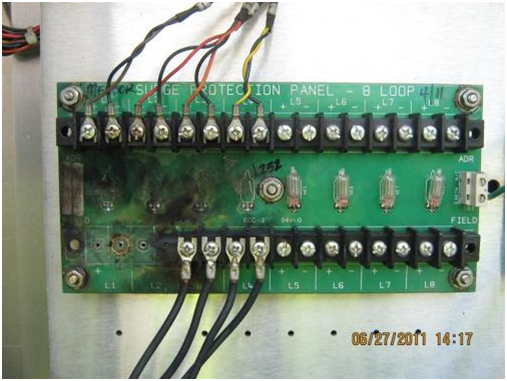
Source: Virginia Department of Transportation
The picture shows a panel of loop field connections in a cabinet after a nearby lightning strike that actually damaged the road. Direct and near direct strikes are unusual. This near strike illustrates the power unleashed. The entire system from power supply to sensors is recommended to be designed and professionally evaluated for surge protection. A standard reference for the design, evaluation, and test regimen is the NEMA TS2 environmental specification for electrical transients. The NEMA TS2 standard sets the environmental requirements for traffic control equipment.
Reliable communication is imperative to the remote traffic monitoring system, especially when data is also used to support real-time operations, such as for incident management, severe weather events, or ITS and traffic operations. While many systems still depend on POTS as their communication backbone, appropriately sized solar panels can easily support wireless data infrastructure. Wireless modems are now available with IP addresses and direct internet access that are very cost effective, provide faster communications, and are significantly more reliable. It is worth noting that when disaster strikes, the wireless internet connection may not be lost at all, and if it is lost, it will be one of the very first services to be restored, because it does not rely on lines, cables, or wooden poles for connectivity.
Please note that these instructions are generalized from Virginia Standard Operational Procedures and equipment, but can be further customized for other devices or local agency preference.
Site Setup Instructions
Most stations in Virginia record volume, classification, length, and speed at the same time. The equipment in use records multiple semi-independent traffic monitoring studies simultaneously.
Classification: Classification is determined using two loops and one piezo in a lane
Volume: Volume count data can be obtained at any and all sites with at least one loop in each lane.
Speed Studies: Speed and length data requires two loops in each lane.
The Electronics are Set for Speed by Length by Channel. 21 speed bins (beginning at 5 mph and ending at greater than 100 mph), 3 length bins (<22 feet, >22 to <45 feet, and greater than 45 feet), Channels (depends on number of lanes at site).
Electronics Standard Setup Steps: Follow the steps and software as provided by the equipment manufacturer. Clear all old settings back to the factory default settings. Allocate file storage and essentials for the agency determined application. Load the (agency) classification scheme.
Set Site-Specific Settings: Set various filters and settings for use. ARM the unit for recording.
Observing Traffic on Site: It is vitally important to observe traffic on site and to evaluate the correct operation of the sensors and electronics.
Check for Accurate Speed, Classification, Counts, Number of Axles, Axle Spacing, Loop Length, and Weights (when applicable). Indicate a YES, NO, or N/A on the inspection form.
Count Accuracy Check: To verify the accuracy of counts during the inspection, the technician will monitor each individual lane separately with the vehicle monitor utility while connected to the electronics. The technician chooses the lane to monitor. Start the vehicle monitoring (typically at a break in traffic). Visually count the number of vehicles in the lane while the monitor also records each vehicle. Stop the vehicle monitor utility. Count the number of records in the utility and compare to the visual count. Repeat these steps for each and every lane
Classification Accuracy Check: To verify the accuracy of classification during the inspection, the technician will again monitor each individual lane separately with the vehicle monitor utility while connected to the electronics. The technician chooses the lane to monitor. Start the vehicle monitoring (typically at a break in traffic).Depending on the type of traffic at the site, the technician will initially verify more distinct class vehicles at the site. For example, Class 9 vehicles stand out in traffic and can be easily verified while using the vehicle monitor. If a high volume of traffic exists at the site, then a visual count and number comparison may need to be done in the same manner as outlined in the “Count” section described earlier.
Electronics Speed Check and Calibration: The accuracy of speeds can be established by direct measurement and comparison. One indicator is the reported wheelbase of the tandem axle on the tractor of Class 9 vehicles. The axle spacing between these two axles should be between 4.0 feet to 4.3 feet. A technician on site can be immediately aware of discrepancies by observing the spacing reported in vehicle monitoring mode. Adjusting the speed calibration of a specific lane requires two people. One person will man the radar gun, taking measurements of vehicles, while a second person will be at the cabinet connected to the Electronics. The calibration should be done one lane at a time.
Debounce: Debounce is a filter that should only be used when site specific installation issues result in a piezo or piezos generating extra axles because of something wrong with the piezo(s) installation or road structure (e.g. slab vibration).
Sensor Tests During Installation: The following tests should be performed by the field installation crews to verify that they have a good working sensor installation while working at a site. At the time of installation, the crews perform initial sensor tests with the presence of an on-site Quality Assurance inspector. After installation is complete, a trained technician revisits the site and performs a complete site final inspection and calibration of all functions
Note: Any loop or piezo sensor found with less than standard readings at time of installation should be immediately replaced, or subject to extended warranty provisions.
Working with the equipment supplier, Virginia has developed a custom classification algorithm (ClassTree) that uses loop logic and makes decisions based on empirical sensor factoring knowledge to accept the data from sites into 22 defined types that is a superset of the FHWA classification system. Post processing then assigns (re-assigns) the “Loop-Logic” classes in the appropriate externally reported class. An example of this action is that a vehicle detected as being 6 to 20 feet long (bumper to bumper) but having only one axle is first assigned to a special bin for strange unicycles and then in post processing, the vehicles from the strange unicycle bin are added to the Class 2 (cars) bin. If this logic and procedure was not in place, the vehicles would be unclassified as type 15s. This logic method and procedure notifies the agency that there is a problem at the site with a piezo not detecting some axles, and yet provides good, usable, accurate data.
Proposed equipment feature sets should always be reviewed and tested in detail to determine whether vendor specific features can enhance the overall quality and capability of the traffic monitoring program. VDOT was able to leverage the availability of a separate data feed for operations data to provide additional data services to internal users, increasing support for the traffic monitoring program.
Technicians install upgraded firmware and perform speed count and classification calibration checks as a normal part of servicing the sites. A technician typically visits each site at least once during each 12-month period either for a service call or a certification visit. During any site visit, a prescribed preventive maintenance procedure is performed that includes brush removal and cabinet cleaning as well as power supply and electronics operational checks. The procedure is quite extensive, involving as many as 216 individual steps, checks, and upgrade operations. As part of the procedure, the onsite technician confirms operation by manual count and classification comparison to machine data, and goes on line with the central office for communication checks. This preventive maintenance process provides greater assurance that site will perform reliably year round and allow early identification of potential issues, facilitating less costly repairs.
Virginia is currently operating several data collection systems, entailing some duplication of effort. As older legacy systems of dial up modems and permanent classification sites are replaced, the cloud-based server system (as is currently used for the non–intrusive and IP based systems) provides enhanced reliability and availability of data while reducing maintenance costs and duplicated efforts. The use of new and enhanced technology provides opportunities for saving fuel and precious budget resources in many areas of traffic monitoring. The internet and wireless IP modems are examples of faster and better availability of data at lower costs. Data servers in the “cloud” make more data available to more people than could be imagined 10 years ago. They offer the ability to put important information in front of operations decision makers 24/7 without human involvement or delay.
All site construction and service call information is maintained online and facilitates remote access to full documentation of all sites and all procedures on line. This serves as a database history of sites and lessons learned.
This case study summarizes the technical guidance available from existing NCHRP and AASHTO reports on the types of traffic data collection equipment available and the associated calibration and validation procedures used with specific types of equipment. Three recent documents are of specific interest to the traffic data collection community.
The first report, NCHRP Report 509, Equipment for Collecting Traffic Load Data was produced as a result of NCHRP Project 1-39 Traffic Data Collection, Analysis, and Forecasting for Mechanistic Pavement Design. NCHRP Report 509 was written to help States understand the equipment options available for collecting the detailed truck volume, classification, and axle weight data needed to effectively use the new AASHTO Mechanical-Empirical Pavement Design Guide (MEPDG.)
A second NCHRP project, NCHRP 3-68 Guide to Effective Freeway Performance Measurement, developed a comprehensive look at the collection, processing, and reporting of the traffic data needed to monitor and report on the operational performance of freeways and expressways. This report includes a chapter on the equipment options available for monitoring traffic flow on high volume, congested urban roadways. The project findings are available in an NCHRP report that is only available on the Internet, NCHRP Web-Only Document 97, Guide to Effective Freeway Performance Measurement: Final Report and Guidebook.
The final report of special significance to users of the Traffic Monitoring Guide is the second edition of the AASHTO report, Guidelines for Traffic Data Programs. This report is an excellent companion guide to the FHWA Traffic Monitoring Guide. It provides a more comprehensive overview of general traffic data collection needs, equipment, and procedures than the two NCHRP reports, which focus on the specific needs of key uses of traffic data. The AASHTO report contains a large, significant chapter on traffic data collection equipment options.
A summary of key information about equipment selection, calibration, and use that is contained in these three reports is provided below.
This report provides detailed descriptions of the technologies used for collecting the vehicle classification (truck volume) and axle weight data needed by States that wish to use the new AASHTO mechanistic-empirical pavement design guide. The report includes:
Included in the technology descriptions are discussions of the types of data that can be collected with each technology (e.g., length based versus axle based vehicle classifications), the environmental limitations inherent in the use of specific technologies (e.g., the performance of many piezo-electric sensors can be affected by cold temperatures), and how operational, geometric, environmental, and other conditions at individual sites should be considered when selecting among available technologies (e.g., the presence of rough pavement indicates that a specific location is a poor choice for a WIM scale, or the fact that blizzard conditions occur reasonably frequently, and thus video technology may not be the best sensor for that location).
The guide provides step-by-step instructions that walk users through the process needed to select traffic data collection equipment appropriate for their needs and conditions. It also provides documentation of best practices needed to operate an efficient, productive data collection program, and helps walk an agency’s staff through those best practices.
The best practice steps include:
One very heavily stressed point in NCHRP Report 509 is the need for equipment calibration. The report points out that many States historically collected large amounts of vehicle classification and weight data while paying little or no attention to their equipment’s calibration. The result was the expenditure of fairly large amounts of money on “data” that had little value because it did not accurately reflect the characteristics of the traffic stream. WIM equipment in particular, has been shown to need careful calibration and periodic refinement of that calibration, as changes in roadway surface condition have large effects on scale and sensor performance. To ensure that the resources spent on WIM data collection result in accurate data, NCHRP 509 provides specific steps for calibrating equipment, and periodically validating the continued accuracy of each site’s performance.
NCHRP Web-Only Document 97, Guide to Effective Freeway Performance Measurement: Final Report and Guidebook is the primary outcome of the NCHRP Project 3-68; Guide to Effective Freeway Performance Measurement. This very large report includes a chapter (Chapter 7 of the main report) on the collection, processing, and reporting of the data needed to monitor the operational performance of freeways and expressways. Several sections of this chapter relate to the collection of volume and speed data
While this report does not include discussions of vehicle classification or weight data, it does provide an excellent summary of the difficulties of collecting accurate traffic data in heavily traveled, congested urban environments, and the strengths and weaknesses of the technologies that are commonly used in those roles. It also presents a brief introduction to the issues associated with purchasing and using vehicle speed data collected and re-sold by the private sector.
This chapter of the report also provides guidance on selecting and purchasing the data collection equipment needed for monitoring and reporting on the performance of these key urban roadways. The steps recommended include understanding and trading off the expected performance of available technologies in the areas of:
These same considerations are appropriate for the selection of equipment used for any traffic monitoring purpose
Published in 2009, the Second Edition of AASHTO’s Guidelines for Traffic Data Programs (Guidelines) contains an entire chapter (Chapter 3) on traffic data collection equipment. The chapter includes a comprehensive discussion of a wide variety of both intrusive and non-intrusive data collection technologies. Following the extensive discussion of alternative data collection devices, the report provides guidance on:
When selecting equipment, the Guidelines recommend that agencies consider the following equipment attributes:
The AASHTO Guidelines correctly and effectively point out that no matter how carefully equipment is selected, if it is installed poorly or inadequately maintained, the “data collected” are often inaccurate and of little or no value. The Guidelines therefore provide best practices for installing and maintaining traffic monitoring equipment. While this section of the report is not a substitute for high quality installation instructions and training from an equipment vendor, the section does provide an excellent source of key quality assurance checks and inspection actions that should be performed when performing equipment installation. It also provides an excellent checklist against which the quality and completeness of a vendor’s instructions and training can be reviewed.
The third section of this Guidelines chapter describes the options agencies have for collecting data on heavily congested roadways where many sensor technologies do not perform accurately. These include: purchasing expensive, but highly capable equipment when the value of the data being collected is greater than the cost of that equipment (e.g., in some toll revenue control applications), placing equipment only where it collects data accurately (i.e., outside of the most heavily congested locations) while sacrificing the ability to observe the most heavy congestion, or developing procedures to identify when congestion is causing the collected data to become unreliable, and adopting procedures that attempt to adjust the collected data to reflect the errors caused by the equipment limitations during those time periods of heavy congestion.
Finally, this chapter describes the traffic control and management system’s requirement for the collection of traffic performance information in order to function as intended. The roadway performance information collected has the potential to meet a large portion of the traffic monitoring needs for the roads those management systems control. Thus, independently collecting data on these same roadways means that duplication of data collection resources is occurring. Consequently, there is considerable benefit to be gained if the general traffic monitoring needs of the agency can be coordinated with the traffic monitoring needs of the traffic management system.

