U.S. Department of Transportation
Federal Highway Administration
1200 New Jersey Avenue, SE
Washington, DC 20590
202-366-4000
Federal Highway Administration Research and Technology
Coordinating, Developing, and Delivering Highway Transportation Innovations
| REPORT |
| This report is an archived publication and may contain dated technical, contact, and link information |
|
| Publication Number: FHWA-HRT-15-074 Date: September 2016 |
Publication Number: FHWA-HRT-15-074 Date: September 2016 |
Based on a literature review and a survey of device manufacturers, owners, and users, the TSD and the RWD were identified as potentially being capable of meeting the project objectives. The term "TSDD" is used to collectively refer to the two devices.
This chapter details the work plan that was developed and implemented for the field trials and subsequent analyses that were carried out over the remainder of the project to accomplish the following objectives:
These objectives and hence the work plan were driven by the analyses that were conducted over the remainder of the project. The work plan was organized into the following sections: analysis methodologies, field trial locations, testing sequence, schedule, and summary.
Rada and Nazarian developed manufacturer-independent specifications required for a number of pavement applications using TSDDs.(19) The authors also provided a comprehensive list of future research needs geared at improving the accuracy and repeatability of the moving pavement deflection testing devices. Those needs were grouped into three major categories: equipment-related, measurement-related, and application-related issues.
The pavement application from the Rada and Nazarian study most relevant to this project is the determination of overall pavement structural capacity indicators/indices. This application serves to assess the overall pavement structural capacity in terms of index values or structural remaining life, and ultimately to support the development of M&R decisions and cost estimates based on structural indicators (comparable to approach used within MicroPAVERTM and other PMSs).(25) However, only the assessment of pavement structural capacity was considered in this work plan, as the development of M&R decisions and costs estimates was beyond the scope of this project. To accomplish the goal of this project, a TSDD must meet the following minimum specifications:
For practicality, a compromise among the precision, accuracy, loss of details with spatial averaging, and speed (and cost) of operation should be made. An optimized level of accuracy and precision should be achieved over a reasonable spatial averaging. The practical threshold values for the accuracy and spatial averaging should be defined based on the pavement structure, pavement responses of interest, and modes of failure associated with these responses.
Figure 5 is an idealized flowchart for accomplishment of the goal and objectives of this project as related to the determination of overall pavement structural condition indicators. Five major activities are identified in the flowchart. Activities 1–3 are desktop studies/analyses that set up the framework for the fieldwork to be done under activity 4. Activity 5 is another desktop study/analysis subtask where the results from the first four subtasks are integrated to recommend an appropriate network-level pavement structural condition assessment algorithm and procedure.
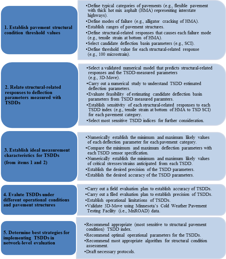
Figure 5. Flowchart. Idealized approach to successful accomplishment of project's objectives.
The five referenced activities also address the remaining project tasks. Activities 1–3 address the validation and evaluation of devices, activity 4 covers the field data collection, and activity 5 addresses the development of analysis methods and processes for incorporation of results into highway agencies' PMS applications. These five activities are detailed next, and changes to the work plan activities are highlighted in future chapters of the report, as applicable.
Since current TSDDs are perceived to be less applicable for rigid pavements, the project team decided, in consultation with FHWA, that the focus of the project would be on flexible pavements. As reflected in figure 5, this first activity consisted in addressing the following issues:
Define Typical Categories of Pavements
The magnitude of surface deflection necessary to indicate the potential damage to a pavement structure is controlled by the type of the pavement (rigid versus semi-rigid versus flexible), the characteristics (thickness and stiffness) of the pavement layers above the foundation, the stiffness of the foundation layer, and the traffic volume. Four levels of traffic and representative ranges of pavement structural parameters were proposed (see table 5 and table 6, respectively). Through Monte Carlo simulation, the project team developed an extensive database of pavement sections.(21) Supplementing this database was the pavement responses from Jacob Uzan Layered Elastic Analysis (JULEA).(26)
| Category | 20-Year Traffic (Thousands of Equivalent Single-Axle Loads (ESALs)) |
|---|---|
| Low | < 500 |
| Medium | 500–3,000 |
| High | 3,000–10,000 |
| Very high | > 10,000 |
| Input | Layer Type | Default | Minimum Value | Maximum Value |
|---|---|---|---|---|
| Modulus (ksi) | AC | 500 | 300 | 700 |
| Base | 50 | 25 | 250 | |
| Subgrade | 10 | 5 | 30 | |
| Thickness (inches) | AC | 5 | 1 | 9 |
| Base | 12 | 6 | 24 |
1 ksi = 6.89 MPa
1 inch = 25.4 mm
Note: Subgrades are usually considered as infinite depth. As a result, no data for subgrade thickness are provided.
Define Modes of Failure
Given that the focus of this project was network analysis, the project team proposed to focus on the traditional modes of failure related to fatigue cracking of AC layer and subgrade rutting for flexible pavements.
Establish Ranges of Pavement Structures
The number of 18-kip (1,440-kN) ESALs to failure for each pavement section based on the two failure criteria was established using criteria similar to those recommended by the Asphalt Institute (AI). The AI equation to predict number of repetitions to fatigue cracking is shown in figure 6, while the AI equation for the number of axle loads to cause 0.5 inch (12.7 mm) of rutting is shown in figure 7.(27)
![]()
Figure 6. Equation. AI fatigue prediction.
Where:
Nf = Number of repetitions to fatigue cracking.
Vb = Effective asphalt content in volume (percent).
Va = Air voids (percent).
εt = Tensile strain at the critical location.
E = Stiffness of the material.
![]()
Figure 7. Equation. AI rutting prediction.
Where:
Nd = Number of axle loads to rut depth failure criteria (0.5 inch (12.7 mm)).
εc = Vertical compressive strain on top of the subgrade.
More mechanistic approaches such as those proposed in the American Association of State Highway and Transportation Officials (AASHTO) Mechanistic-Empirical Pavement Design Guide (MEPDG) or CalME, a software program developed by Caltrans/University of California Pavement Research Center using the mechanistic-empirical methodologies for analyzing and designing the performance of flexible pavements were used.(28,29) Pavement structures that preliminarily yielded a design life of 10–40 years for each traffic category were delineated. The distribution of pavement structures along with the mean, median, and standard deviation were used to develop the representative ranges of pavement structures for each traffic category. These results are presented in section 8.4, Relationship Between Indices and Critical Response.
Define Structural-Related Responses
The primary structural responses considered were the tensile strains/stresses at the bottom of the AC and the compressive strains/stresses at the top of subgrade. In addition, the compressive strains/stresses in the middle of the AC and base/subbase were considered as surrogates for the rutting of the AC and base/subbase, respectively, when the rutting failure mode was considered.
Select Candidate Deflection Basin Parameters
Based on the FWD measurements, a number of deflection-basin related parameters that were perceived as strong predictors of the critical structural-related responses and structural conditions of the pavements were proposed. Horak and Emery provided an algorithm for using FWD-derived indices for airfield pavement evaluation, while Thyagarajan et.al. proposed a process for using indices for highway pavements.(30,21) The FWD-measured deflections were simulated for the pavement sections developed under item 1 of this activity (i.e., define typical categories of pavements) and to estimate these and similar deflection basin parameters. Some of these parameters are presented in figure 8 through figure 18.

Figure 8. Equation. Definition of radius of curvature R1.
Where:
r = Distance from the load.
D0 = Deflection under the load.
Dr = Deflection at a distance r from load.

Figure 9. Equation. Definition of radius of curvature R2.
![]()
Figure 10. Equation. Definition of deflection basin area (A).
Where:
Di = Deflection at i inches away from load.
![]()
Figure 11. Equation. Definition of shape factor F1.
![]()
Figure 12. Equation. Definition of shape factor F2
![]()
Figure 13. Equation. Definition of SCI.
![]()
Figure 14. Equation. Definition of Base Curvature Index (BCI).
![]()
Figure 15. Equation. Definition of Base Damage Index (BDI).
![]()
Figure 16. Equation. Definition of slope of deflection (SD).
![]()
Figure 17. Equation. Definition of area under pavement profile (AUPP).
![]()
Figure 18. Equation. Definition of tangent slope (TS).
Where:
dD = Difference in deflection.
dr = Difference in distance.
Define Threshold Value for Each Structural-Related Response
Ideally, TSDDs are able to provide adequate data accurately and precisely enough so that the performance history of a pavement section can be estimated with reasonable accuracy before any functional or structural distresses are evident. In this ideal process, the critical strains (e.g., tensile strain at the bottom of the AC) are small enough, and the model for estimating performance of the pavement with time is accurate enough so that highway agencies can conduct what-if analyses (considering life-cycle cost analysis) to make more informed decisions about the best use of their M&R budgets. The project team strived to reach that level of capability. The following items were addressed to evaluate whether the suggested process could be implemented in the near future:
The subsequent activities, especially activity 4 (field evaluation of devices in figure 5), were designed to answer the first three questions comprehensively. It was thought that the fourth question could be addressed through close collaboration between FHWA and project teams.
An alternative way of establishing the thresholds considered was to conduct simple structural analyses to estimate the remaining life from the time of testing. The relevant structural responses for the representative pavement structures in each traffic category corresponding to 2, 5, and 10 years[1] of remaining life were preliminary considered as the thresholds for deteriorated, marginal, and well-performing pavements, respectively. In other words, if the critical strains/stresses exceeded the 2-year remaining life thresholds, the pavement was considered a candidate for reconstruction, and if the critical strains/stresses were less than the 10-year thresholds, the pavement was considered in good condition. Pavements with remaining lives of 2–5 years were considered candidates for major rehabilitation, and pavements with remaining lives between 5 and 10 years were considered candidates for maintenance or light rehabilitation.
These concepts were revisited after field data with TSDDs became available to develop the best strategies for implementing TSDDs (addressed as part of activity 5).
The analyses proposed under activity 2 were based on the traditional static layered elastic algorithms. The TSDDs used proprietary hardware and software to estimate dynamic surface deflection parameters imparted by the moving tire loads. Since the trucks carrying the devices often traveled at traffic speeds, the resulting dynamic surface responses were affected by inertia and damping of the layered pavement system. The evaluation of the capabilities of these devices was therefore undertaken by a computational model that is capable of modeling moving loads traveling on a layered medium. The five issues addressed under this activity are as follows:
Using a Numerical Model to Predict Structural-Related Responses and TSDD-Measured Parameters
The computer software 3D-Move is ideally suited to evaluate and compare pavement responses measured with TSDDs. 3D-Move estimates the dynamic pavement responses at any point within the pavement structure using a continuum-based finite-layer approach. The 3D-Move model can account for important pavement response factors such as the moving traffic-induced complex three-dimensional contact stress distributions (normal and shear) of any shape, vehicle speed, and viscoelastic material characterization for the pavement layers. (See references 2 and 31–33.) The pavement surface deflection is affected by many factors that include pavement layer characteristics (thickness and stiffness properties), vehicle speed, and damping. Damping in particular plays a major role in the form of time lag between the loaded tire and the deflection response. The 3D-Move model uses viscoelastic formulation and complex frequency domain analyses, such that damping can be specified as either a single value or as a function of frequency. For each of frequency considered in the fast Fourier transform (FFT), the corresponding damping (frequency dependent, if required) was selected and used to obtain the imaginary part of the modulus.
Since rate-dependent (viscoelastic) material properties can be accommodated by 3D-Move, it was considered an ideal tool to study pavement response as a function of vehicle speed through the direct use of the frequency sweep test data (dynamic modulus and damping) of AC mixture.
Several field validations (e.g., Penn State University test track, MnROAD, and University of Nevada-Reno (UNR) Off-Road Vehicle study) that compared a variety of independently measured pavement responses (stresses, strains, and displacements) with those computed by 3D-Move have been reported in the literature. (See references 34, 35, 31, and 33.) Hajj et al. reported that the responses from 3D-Move were within 6 percent of those estimated by ViscoRoute developed by Chabot et al. for thin and thick pavements.(36,37) Those studies demonstrated the applicability and versatility of the 3D-Move approach. Further validation of 3D-Move to strengthen the validity of its application in relating device measurements to structural responses was carried out as part of the field evaluation of the devices as discussed under activity 4.
Understanding TSDD Estimated Deflection Parameters
Each TSDD has its own way of calculating deflection parameters. The TSD measures the surface vertical velocity at as many as nine points[2] (in the front from the mid-point between the dual tires) within the deflection bowl using a Doppler laser technology. The vertical velocity measurements were divided by the vehicle speed to arrive at the slopes of the deflected shape at the measuring locations. These slopes were then fitted to a deflection bowl to estimate the surface deflection at the mid-point between the tires (D0) and other locations.
The RWD used six spot lasers mounted on a horizontal aluminum beam to measure the deflected pavement surface (longitudinally along the midpoint between the dual tires). Two sensors (sensor D located 7.25 inches (184 mm) behind the axle and sensor F located 7.75 inches (197 mm) in front of the axle in figure 19) were within the deflection bowl, while the other four sensors represent locations within the undeflected pavement surface. The A, B, C, and E sensor readings were used to obtain the load-induced surface deflection at the location of sensors D and F. The following questions were addressed as part of these simulations:
 sensor locations. Sensor locations are labeled A through F from right to left. Sensors A, B, C, and D are located 102 inches (2.591 mm) from each other. Sensor E is located between sensors B and C 15 inches (381 mm) from sensor C. Sensor F is located between sensors C and D 15 inches (381 mm) from sensor D. Sensor D is located 7.25 inches (184.15 mm) behind the axle, and sensor F located 7.75 inches (196.85 mm) in front of the axle. The direction of travel is from left to right.")
1 inch = 25.4 mm
Figure 19. Illustration. RWD sensor locations.
| Activity | Description of Activity |
|---|---|
| Experiment plan | A subset of as many as 32 cases from database from table 6 based on analyses performed in activity 4. |
| How |
|
| Further action | Synthesize and scrutinize deflections looking for correlation and trend relative to pavement structure and material properties. |
1 inch = 25.4 mm
| Activity | Description of Activity |
|---|---|
| Experiment plan | Same (up to 32) cases considered in table 7 but with different vehicle velocities. |
| How |
|
| Further action | Synthesize and scrutinize deflections looking for correlation and trend relative to pavement structure and material properties. |
| Activity | Description of Activity |
|---|---|
| Experiment plan | Use same databases reflected in table 7 and table 8. How does the speed of test vehicle impact the measured deflection parameters? Field studies revealed that vehicle speed played a significant role in pavement response. Though the devices under consideration were designed to operate at or close to posted traffic speeds, the vehicles may operate at lower speeds for a variety of reasons. The role of vehicle speed on the measured pavement deflection is important, especially if a comparison is to be made between the date from the same TSDD traveling at different speeds. The speed of the vehicle may also impact the optimal location of the sensors. Table 8 provides the experiment plan that was adopted with 3D-Move to investigate the role vehicle speed. If the speed of the vehicle impacted the optimal location of the sensors, a strategy to recommend the best compromise on the location of the sensors could be developed (supplement if necessary). |
| How |
|
| Further action | Synthesize and scrutinize deflections looking for correlation and trend relative to pavement structure and material properties |
Evaluating Feasibility of Estimating Candidate Deflection-Basin Parameters from TSDD-Measured Parameters:
For practical implementation, it was considered highly desirable to simulate the TSDD-measured parameters and to estimate the candidate deflection-basin parameters established under activity 1 for estimating the pavement structural conditions.
Establishing Sensitivity of Structural-Related Responses to Each TSDD-Measured Parameter and Index
The pavement structure database or its subset was used as input to 3D-Move to estimate the relevant deflection parameters and corresponding indices selected in activity 2 at three vehicle speeds: slow (20 mi/h (32.2 km/h)), intermediate (40 mi/h (64.4 km/h)), and fast (60 mi/h (96.6 km/h)). The two databases were merged for further statistical analyses to address the following:
Selecting Most Sensitive TSDD Indices for Further Considerations
Through correlation and sensitivity analyses explained in the previous item, the most representative indices associated with different modes of failure were identified for further field validation.
The outcomes of activities 1 and 2 were used to establish the ideal measurement characteristics. The five issues addressed under this activity were as follows:
The deflection measurement that defines the minimum requirements for the capable devices include the accuracy of measurements, precision of measurements, and a number of other items that are categorized under operational limitations of devices. To summarize this information, the parameters that support or validate the interpretation of the data collected with a device are not straightforward. This is because the response parameters cannot be measured directly; the raw data collected with a TSDD have to be combined with the pavement structure and pavement conditions through either empirical, analytical, or numerical algorithms to estimate the critical strains/stresses within or at the interfaces of pavement layers. Accordingly, a rigorous field study was required to evaluate, validate, and improve the numerical results and suggested criteria for estimating the structural conditions of the pavements from the parameters measured with the TSDDs. The bulk of the field study activities were carried out at the Minnesota Department of Transportation (MnDOT) MnROAD facility located north of Minneapolis, MN; the basis for selecting this facility for use in the study is provided in section 4.2, Field Trial Locations. The specific issues addressed as part of field study activity include the following:
Accuracy of Deflection Measurements
The accuracy of the measurements was determined by comparing the reported values from each device with the same values from an external sensor. The main focus of the determination of the accuracy was the deflection parameters measured by the devices. The RWD estimated the surface deflection using a spot laser, and the TSD measured the surface velocity using Doppler laser technology. Table 10 summarizes of the objectives and other factors related to this experiment. A comparison of the deflection parameters measured at the densest interval with each device with the deflection parameters measured with embedded sensors at the surface of the pavement was proposed.
| Activity | Description of Activity |
| Hypothesis | TSD/RWD reported deflections or deflection velocities are the same as the deflections or deflection velocities experienced by pavement. |
| Data requirements |
|
| Experiment design |
|
| Pre-testing actions |
|
| How |
|
| Further action | If the hypothesis is rejected:
|
Based on the status report of the MnROAD sensors that measure displacement parameters (i.e., embedded linear variable differential transformers (LVDTs) and accelerometers), they did not function reliably. As such, the project team decided to retrofit pavement test sections with appropriate surface sensors for this activity. Three alternative sensors (LVDTs, geophones, and accelerometers) were considered as possible candidates for embedded sensors, as outlined in  table 11. It was decided to primarily use geophones for accuracy purposes since they are the least expensive, can be easily ruggedized in a steel casing, and have one-to-one correspondence to the deflection parameters measured by the TSD. In addition, one accelerometer was used at each accuracy test section to verify the responses of the retrofitted geophones.
| Sensor | Advantage | Disadvantage |
|---|---|---|
| LVDT |
|
|
| Geophone |
|
|
| Accelerometer |
|
|
A secondary parameter related to the accuracy of the measured deflection parameters is the instantaneous applied load to the pavement. The impact of pavement roughness on the instantaneous load applied to the pavement is documented in the literature.(38,39) The state of the practice in the analyses of the TSDD deflection data is usually based on the assumption that the instantaneous load is equal to the static load, but in this project, the impact of the variation in the instantaneous load on the performance of the devices was studied. The TSD was equipped with instrumentation to measure the instantaneous applied loads concurrent with the deflection measurements. Such measurement is currently lacking from the RWD. Instrumenting the test sections for directly measuring the instantaneous load seemed impractical. However, since the TSD was equipped to estimate the load applied to the pavement, an evaluation of the potential benefits of normalizing measured TSD deflection parameters with loads reported by the device was carried out.
Table 12 summarizes the objectives and other factors related to this experiment.
| Activity | Description of Activity |
|---|---|
| Hypothesis | Instantaneous applied load is equal to static axle load and does not significantly impact results from TSDD analyses. |
| Data requirements | Dynamic loads measured with TSD concurrent with deflections at the densest interval possible. |
| Experiment design | Same as table 10 plus all other feasible sections of MnROAD. |
| Pre-testing actions |
|
| How (only on TSD) |
|
| Further action | Document implication of not measuring instantaneous dynamic loads on evaluating structural condition of pavements. |
Precision of Deflection Measurements
The precision of the measurements is estimated by comparing the reported values from replicate measurements in a short period of time. Table 13 summarizes the objectives and other factors related to this experiment.
| Activity | Description of Activity |
|---|---|
| Hypothesis | TSDD measurements repeated over a short period are adequately precise for network-level analysis of structural condition. |
| Data requirements | Deflection parameters measured five times with TSDDs at the densest possible intervals. |
| Experiment design |
|
| Pre-testing actions | Establish preliminary precision desired for network-level applications. |
| How |
|
| Further action | Document implication of estimated TSDD precision on delineating structural condition of pavements if hypothesis is rejected. |
Operational Limitations of Devices
Although the major technical issues can be conceptually addressed with the established levels of accuracy and precision, many other practical parameters can also impact how well the condition of the pavement can be assessed and were therefore considered in this project. These practical parameters can be optimized to ensure that the maximum information can be robustly extracted from the devices. Marginal additional data collection was needed for this purpose; the data collected under the previous two items of this activity (i.e., accuracy of deflection measurements and precision of deflection measurements) were processed differently to address most of these issues. Those issues were as follows:
Validation of 3D-Move Using MnROAD Data
Existing pavement response measurements on flexible pavements at MnROAD facility include strain responses in longitudinal (vehicle direction) and transverse directions and vertical pressure histories in base and subgrade layers (see table 10). MnROAD contains more than 90 reliably operating longitudinal and transverse dynamic strain gauges in flexible pavement cells and more than 40 dynamic pressure gauges in the foundation layers. These measurements were directly compared with those computed by 3D-Move. Since the project focus was on AC layer condition, attention was given mainly to AC strain measurements. The 3D-Move modeling requires pavement layer configurations and properties and traffic loading. An existing MnROAD database of material properties, which include FWD data and also viscoelastic characterization (dynamic modulus and damping) of AC properties (e.g., master curve of frequency sweep data), were used. The tire load measurements provided the information on the tire-pavement interaction load.
In addition, data collected from the supplementary embedded surface geophones were also used in the validation. The durations of the time histories were variable (based on the vehicle speed) to cover a distance of ±15 ft (4.58 m) from the embedded sensor. Based on preliminary analysis using 3D-Move, the spacing between geophones was determined to ideally be about 5–6 inches (127–152 mm) at a number of locations. The measured velocity time histories from the geophones along with the estimated displacement time histories were relevant since they were the basic measurements that were used by the TSDD under consideration.
The main goal of this activity was to integrate the outcomes from the previous four activities into a coherent set of practical guidelines and protocols for the successful implementation of the TSDDs in network-level structural condition assessments for use in State transportation department PMS applications. Additional data analyses and alternative data interpretation algorithms were considered. Based on the outcomes of the 3D-Move validations, additional simulations were also carried out. The four issues addressed under this activity include the following:
To support the analysis methodologies detailed in the previous section of the report, the field trial location(s) should provide the following pavement factorial parameters:
Other testing considerations required by the analysis methodologies include varying temperatures and device speeds. These considerations could be taken into account in determining the field location(s) but could also be controlled once the field locations were selected by varying the time of day the testing occurred to control temperature or the speed of the device, provided varying the speed of the device did not pose a safety concern.
Several potential field trial locations were considered to fulfill the requirements mentioned, including the MnROAD facility; instrumented test sections in Kansas, Ohio, and New York; and test sections previously used in the evaluation of the RWD in Louisiana.
This chapter presented a detailed work plan developed for the remainder of the project, including analysis methodologies and field trial locations. The details provided in this chapter were developed to accomplish the following two objectives:
The decision was made to hold the field trials at the MnROAD facility because it provides a multitude of test sections in one location and contains readily available information, including environmental and dynamic load response data. In addition to the MnROAD test sections, additional field trial testing was planned on an 18-mi (29-km) loop located in Wright County, MN, near the MnROAD facility.
1 These values were considered preliminary, for the purposes of the work plan, and are subject to change during the analyses.
2 The TSD that was used in the field trials discussed in chapter 5 only had six points.

