U.S. Department of Transportation
Federal Highway Administration
1200 New Jersey Avenue, SE
Washington, DC 20590
202-366-4000


Skip to content
Facebook iconYouTube iconTwitter iconFlickr iconLinkedInInstagram

Federal Highway Administration Research and Technology
Coordinating, Developing, and Delivering Highway Transportation Innovations

 
REPORT
This report is an archived publication and may contain dated technical, contact, and link information
Back to Publication List        
Publication Number:  FHWA-HRT-13-066    Date:  August 2013
Publication Number: FHWA-HRT-13-066
Date: August 2013


Geosynthetic Reinforced Soil Performance Testing - Axial Load Deformation Relationships

APPENDIX C. DEFORMATION INSTRUMENTATION LAYOUTS FOR PTS

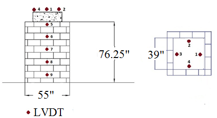
Figure 107. Illustration. Instrumentation layout for DC tests and TF-1. Side view and cross section of mini-pier showing arrangement of concrete masonry units and locations of linear voltage displacement transducers on the face and concrete footing used to measure lateral and vertical deformation, respectively.
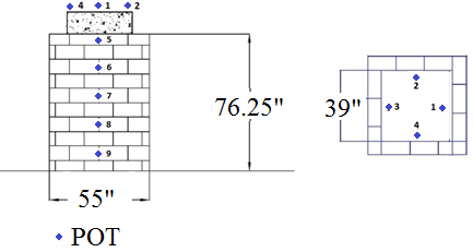
Figure 107. Illustration. Instrumentation layout for DC tests and TF-1.

Figure 108. Illustration. Instrumentation layout for TF-2, TF-9. Side view and cross section of mini-pier showing arrangement of concrete masonry units and locations of string potentiometers on the face and concrete footing used to measure lateral and vertical deformation, respectively.
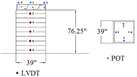
Figure 108. Illustration. Instrumentation layout for TF-2, TF-9.

Figure 109. Illustration. Instrumentation layout for TF-3, TF-4. Side view and cross section of mini-pier with no facing, showing arrangement and locations of linear voltage displacement transducers and string potentiometers used to measure deformation. The POTs are located on the concrete footing to measure vertical deformation while the LVDTs are located on the side of the GRS composite to measure lateral deformation.
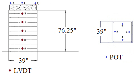
Figure 109. Illustration. Instrumentation layout for TF-3, TF-4.

Figure 110. Illustration. Instrumentation layout for TF-5, TF-7. Side view and cross section of mini-pier with no facing, showing arrangement and locations of linear voltage displacement transducers and string potentiometers used to measure deformation. The potentiometers are located on the concrete footing to measure vertical deformation while the LVDTs are located on the side of the GRS composite to measure lateral deformation.
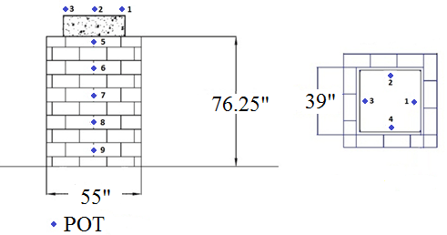
Figure 110. Illustration. Instrumentation layout for TF-5, TF-7.

Figure 111. Instrumentation layout for TF-6, TF-12. Side view and cross section of mini-pier with no facing showing arrangement of concrete masonry units and locations of string potentiometers on the footing and face of the wall used to measure vertical and lateral deformation, respectively.
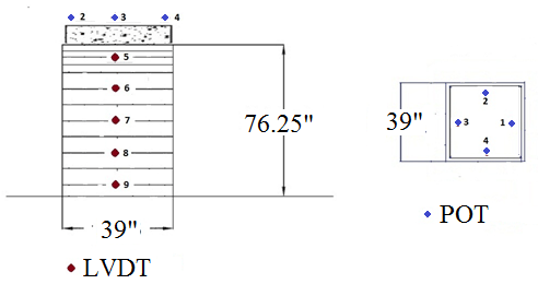
Figure 111. Instrumentation layout for TF-6, TF-12.

Figure 112. Illustration. Instrumentation layout for TF-8. Side view and cross section of mini-pier, showing arrangement of concrete masonry units and locations of linear voltage displacement transducers on the side of the GRS composite and string potentiometers on the footing used to measure lateral and vertical deformation, respectively.
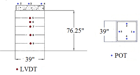
Figure 112. Illustration. Instrumentation layout for TF-8.

Figure 113. Illustration. Instrumentation layout for TF-10. Side view and cross section of mini-pier with no facing, showing arrangement and locations of linear voltage displacement transducers on the side of the GRS composite  and string potentiometers on the footing used to measure lateral and vertical deformation, respectively.
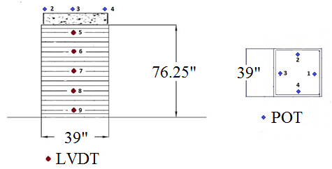
Figure 113. Illustration. Instrumentation layout for TF-10.

Figure 114. Illustration. Instrumentation layout for TF-11. Side view and cross section of mini-pier showing arrangement of concrete masonry units and locations of linear voltage displacement transducers on the side of the GRS composite  and string potentiometers on the footing used to measure lateral and vertical deformation, respectively.
Figure 114. Illustration. Instrumentation layout for TF-13
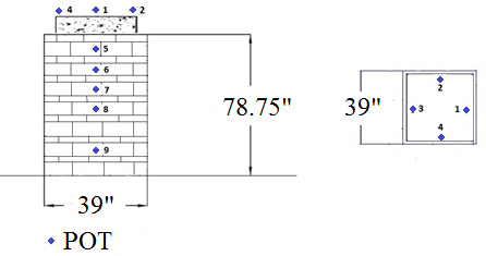
Figure 115. Illustration. Instrumentation layout for TF-13. Side view and cross section of mini-pier with no facing, showing arrangement and locations of linear voltage displacement transducers on the side of the GRS composite  and string potentiometers on the footing used to measure lateral and vertical deformation, respectively.
Figure 115. Illustration. Instrumentation layout for TF-14