U.S. Department of Transportation
Federal Highway Administration
1200 New Jersey Avenue, SE
Washington, DC 20590
202-366-4000
Federal Highway Administration Research and Technology
Coordinating, Developing, and Delivering Highway Transportation Innovations
| REPORT |
| This report is an archived publication and may contain dated technical, contact, and link information |
|
| Publication Number: FHWA-HRT-14-049 Date: August 2014 |
Publication Number: FHWA-HRT-14-049 Date: August 2014 |
Dampers are frequently used to suppress excessive vibration of stay cables which have limited intrinsic damping. These dampers, due to practical limitations of installation, are usually attached to the stay cables near the anchorages. Although theories behind the observed behavior of stays with attached dampers are not completely developed, dampers have been widely used, and their effectiveness has been demonstrated by many examples. Application of dampers for cable vibration mitigation is anticipated to be more widespread, and the need for improved understanding of the resulting dynamic system is increasing. The effectiveness of different strategies involving external dampers and crossties for mitigation of stay cable vibrations is investigated via finite element simulations.
CONFIGURATION AND DAMPER COEFFICIENT
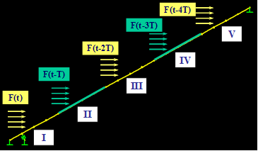
Figure 121 shows a single stay with a viscous damper attached near the anchorage. The distance of the damper from the deck anchorage is 2 percent of the chord length of the cable (d = 0.02 L). The stay simulates Cable SWC-01 of the Cape Girardeau Bridge, whose properties are presented in table 2 and table 3 (see cable 1). A sequential wind loading on the cable is shown in figure 122, in which F(t) denotes the horizontal wind force history shown in figure 99.

Figure 121 . Image. Stay cable with a viscous damper attached to it.

Figure 122 . Image. Sequential wind loading on the cable.
The optimal damping coefficient (Copt) for the cable is determined from the universal damping curve shown in figure 123. This asymptotic analytical curve proposed by Krenk is valid when d/L, the relative damper distance from the support, is very small.(15)

Figure 123 . Graph. Universal damping curve.
The curve relates the normalized damping ratio ζi/(d/L) to the normalized damping coefficient (κ) defined as follows:
![]()
Figure 124 . Equation. Normalized damping coefficient.
Where:
C = Damper coefficient.
m = Cable mass per unit length.
ω1 = First mode natural frequency.
ζi = Damping ratio of the ith mode of vibration.
i = Mode number.
At optimal damping, the normalized damping ratio reaches 0.5 and κ approaches 0.1, from which C-values are determined for different modes. The achievable modal damping ratios are limited by this relationship. For example, for d/L of 2 percent, the achievable maximum damping ratio for the first mode is 1 percent.
RESPONSE TO REFERENCE WIND LOAD
Figure 125 and figure 126 show the horizontal components of the displacement histories computed at the mid- and quarter-span of the stay without and with a damper, respectively. It can be seen that the use of a damper reduces the vibration amplitudes of the stay. Figure 127 shows the energy evolution of the stay without and with a damper, respectively. Both the potential and kinetic energies are reduced due to the incorporation of a damper; however, the reduction of kinetic energy is more pronounced than that of potential energy. When damper is not used, the energy of the cable is dissipated entirely by intrinsic modal damping. A uniform modal damping of 0.3 percent is assumed. When a damper is used, the majority of the energy is dissipated via the damper, and only a small fraction of the energy is dissipated via intrinsic damping of the cable.

Figure 125 . Graph. Displacement computed at mid-span of the cable without damper (left) and with damper (right).

Figure 126 . Graph. Displacement computed at quarter-span of the cable without damper (left) and with damper (right).

Figure 127 . Graph. Energy evolution of the cable without damper (left) and with damper (right).
Figure 128 and figure 129 show the PSD distributions for the displacement profiles computed at the mid- and quarter-span of the stay, respectively. Without damper, vibration took place primarily in the first and third modes, whereas when a damper was installed, the vibration was mostly in the first mode, and only a small trace in the third mode was observed. According to the theory, the use of a damper shifts the natural vibration frequencies of the stay; however, in this particular example, the amount of shift appears to be very limited.

Figure 128 . Graph. PSD for displacement at mid-span of the cable without damper (left) and with damper (right).

Figure 129 . Graph. PSD for displacement at quarter-span of the cable without damper (left) and with damper (right).
Figure 130 shows the energy evolution of a single cable without and with a damper subjected to wind-hf. The effectiveness of the use of a damper is more pronounced when a stay is subjected to a wind event that contains enriched high-frequency components. In other words, dampers are more efficient in mitigating stay vibrations containing appreciable high-frequency components. The major portion of the vibration energy is dissipated via the damper. It is to be noted that dampers are effective in mitigating transverse and in-plane vibrations when separate dampers are installed in the respective directions of motion.

Figure 130 . Graph. Energy evolution of the cable under wind-hf without damper (left) and with damper (right).
INFLUENCE OF DAMPER PARAMETERS
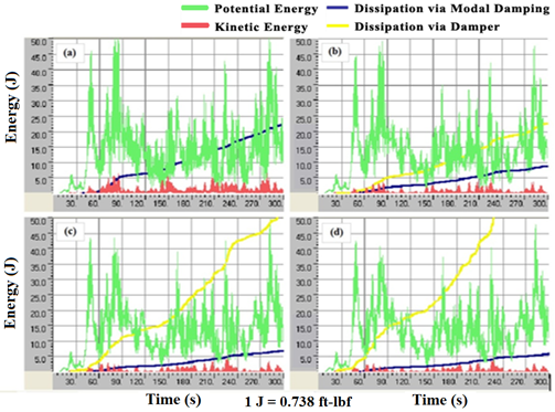
The efficiency of a damper depends primarily on its damping coefficient and its location on the stay, among other factors. In order to test the influence of damping coefficient (or damper coefficient), four different levels of damping were considered: C = 0 (no damper), C = Copt, C = 0.1 Copt, and C = 10 Copt. Results are shown in figure 131, which highlights the evolution of the potential and kinetic energy of a cable/damper system subjected to wind-1. Also shown are energies dissipated through intrinsic modal damping and through the damper.

Figure 131 . Graph. Energy evolution of the cable when different levels of damper coefficient are used—(a) C = 0 (no damper), (b) C = Copt, (c) C = 0.1 Copt, and (d) C = 10 Copt.
As can be expected, the cable performed best when the damper had its optimal coefficient, C = Copt. Energy levels, especially kinetic energy, are lowest when the optimal value is used. It can be seen that with the optimal damper coefficient (see graph b in figure 131), the amount of energy dissipated through the damper is greatest, and the demand of energy dissipation through the cable's intrinsic modal damping is minimal. Dissipation by modal damping is proportional to kinetic energy due to their dependence on velocity. Therefore, less dissipation by modal damping signifies a lower level of kinetic energy, meaning lesser cable vibrations.
To test the influence of damper location, four different cases were considered. Figure 132 shows results for C = 0 (no damper), d/L = 0.02, d/L = 0.05, and d/L = 0.10, where d is the offset distance of the damper from anchorage, and L is the chord length of the stay cable. The case of d/L = 0.10 gives the largest energy dissipation through the damper, and the achieved kinetic energy level is lowest among the four cases considered, signifying its being the most effective in vibration mitigation. However, due to practical limitations associated with installation, dampers are usually attached to stays near the anchorages.

Figure 132 . Graph. Energy evolution of the cable when different damper locations are used—(a) C = 0 (no damper), (b) d/L = 0.02, (c) d/L = 0.05, and (d) d/L = 0.10.