

Manual on Use of Self-Propelled Modular Transporters to Remove and Replace Bridges
Chapter 4. Design
4.1. Design Assumptions
Design assumptions used to develop project details include the following:
- Built-in-place substructures are constructed within tolerances to allow placement of the superstructure with adequate clearance.
- Actual lifting points for the move are the same as shown in the lifting diagrams the contractor submitted and the owners approved.
4.2. Ground Bearing Capacity
The contractor must prepare the ground for adequate bearing at the staging area for construction of the bridge on temporary supports, and along the path from the staging area to the final bridge location to resist the weight of the loaded SPMTs. Relationship between ground pressure and base preparation is shown in figure 4.
Figure 4: Relationship between ground pressure and base preparation (courtesy of Sarens Group)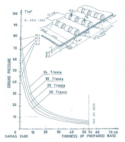
4.3. Temporary Shoring Bents at Staging Area
The temporary shoring bents (supports) should be designed using the AASHTO Guide Design Specifications for Bridge Temporary Works. Elevation tolerances should be specified.
The temporary supports must provide equal load distribution among beams and have adequate foundation capacity to prevent settlement before, during, and after construction of the superstructure. Monitoring should be in place to detect settlement.
The distance between temporary supports must be the same as between the final substructures. The caps of temporary supports will be constructed with beam bearing seats in the same relative position as plan elevations for cross-slope, superelevation, and grade. The beams should sit on the same bearing pads or configuration of bearings used in the final location.
The temporary supports must provide a minimum 5-ft (1.5-m) clear distance from the ground surface to the bottom of the beams to allow the SPMTs to move under the spans for lifting.
The caps of the temporary supports must be at least 4.25 ft (1.29 m) wide to accommodate blocking stacks and jacks for lifting. The caps must provide a flat surface to allow all jacks to be at the same elevation.
An as-built field survey should be conducted to verify dimensions and relative elevations.
4.4. Prefabricated Superstructures
Temporary support conditions for the superstructure are to be the same as final support conditions, including dimensions, cross-slope, superelevation, and grade. Allowable elevation tolerance of beam pedestal should be provided.
Longitudinal, horizontal, and vertical dimensions of the superstructure must allow for erection tolerances at the permanent substructures and for transverse deck joint design requirements, for example, a 1-in (2.5-cm) joint at abutments.
Assumed lifting points for the span should be provided.
An as-built field survey should be conducted to verify dimensions and elevations.
Details that address fit-up should be provided, including preformed anchor bolt holes, stainless steel shimming at bearing locations, and, if called for, making the deck continuous over the interior supports after installation.
See "4.9 Possible Design Efficiencies" for options to reduce dead load and improve the efficiency of the move.
4.4.1. Decks
Consideration should be given to scheduling deck casting to ensure proper final deck tolerances to allow adjustments for the as-built condition. A portion of the deck at the ends of the span, for example, 5 ft (1.5 m) from the ends, may be cast in place after the spans are installed. This can facilitate installation, allow flexibility for joint details, and result in improved rideability. Example plan sheet details for a cast-in-place deck closure pour option to facilitate span fit-up are in Appendix B.
An additional sacrificial thickness, for example, 0.5 in (1.2 cm), should be considered in the deck design to accommodate grinding to achieve rideability.
For multibeam spans, the concrete decks must attain design compressive strength before lifting. For truss or arch spans, decks may be constructed after the move to reduce self-weight during the move; bracing must be adequate to prevent excessive distortion.
4.5. Substructures
Cast-in-place substructures must be built within tolerances to allow placement of superstructures with adequate clearance.
4.6. Allowable Temporary Stresses and Deflections
Lifting and moving a bridge with SPMTs usually results in a condition in which the bridge will be temporarily supported at locations that are not the final support points. The designer should check the bridge under these temporary support conditions. Structural members will likely see stress reversals that may be detrimental. An impact factor should be added to the dead load to account for movement on uneven surfaces; a value of at least 15 percent is recommended.
The analysis should also account for the SPMT hydraulic system, which will essentially provide equal bearing at each support. This is especially true for larger bridges where multiple sets of interconnected SPMTs are proposed. The SPMTs will provide soft support for the bridge. Appropriate spring coefficients need to be applied at each support so that the bridge will experience essentially equal reactions. This will result in a redistribution of dead load stresses in the bridge.
The designer should calculate and specify an accurate bridge weight, especially for large bridges. For example, a steel fabricator's estimates are not for the finished product because cutting waste has not been included; the final weight of each piece is not determined until the shop drawings are complete. Simple rule-of-thumb weight estimates for items such as cross frames and diaphragms may not be good enough, and the weight of a coating system alone can be substantial. Accuracy is needed to provide an adequate lifting operation.
The contractor should provide the jacking forces and procedures for lifting a superstructure from its temporary supports to its setting height before installation, and the jacking procedures for lowering a removed superstructure from its setting height to a lower height for demolition.
The contractor should provide analysis of jacking, moving, and erection loads to ensure that temporary stresses and deflections are within allowable values for the bridge and that the bridge is adequately reinforced to handle the calculated temporary stresses without cracking (for example, deck tensile stress). The analysis should include the number of jacking towers at the ends of the span, the jacking force per jack, and the locations of the jacks along the beam length. Jacks at each end are to be connected to each other to push and support equal loads.
The SPMTs will typically lift the bridge spans as near to the final support positions as possible to minimize installation stresses. Lifting points for the move will be controlled by SPMT width and available clearance between obstacles.
Temporary overstresses on the bridge should not be allowed during lifting and moving. Geometric tolerances should avoid excessive stresses while permitting an optimum speed of movement.
The contractor should verify that the bridge is adequately braced during the move (for example, end and intermediate diaphragms of superstructure spans are constructed before transporting).
4.7. Wind Loading
The contractor will provide analysis of wind loads on the bridge at its temporary location and during the move.
The owner should specify a design wind load for movement of bridges. If the owner does not specify the wind speed or load, the owner should be flexible when the contractor chooses a wind speed for the move. Using the AASHTO design load is probably too conservative. The wind speed should be based on statistical analysis that includes the probability of occurrence. Thunderstorms can pop up quickly; just looking at the weather report before a move is not always safe.
An American Society of Civil Engineers (ASCE) document on wind loading during construction is available.(5) This document gives recommendations for reducing the design wind speed based on duration of construction. It should be used for all erection procedures.
4.8. Single-Span Versus Multispan Movements
The advantages of moving multiple-span bridges during one operation include reducing the impact to traffic, eliminating the deck joint(s) at the interior support(s), and improving rideability across the interior supports.
More coordination and close monitoring of stresses and deflections are required for a multispan bridge move to ensure that allowable stresses and deflections are not exceeded (for example, to avoid deck cracking). Greater attention to structural details, ground stability during the move, and equipment synchronization are required. A larger staging area, deeper foundations for the temporary supports, and a wider path from the staging area to the bridge site are also required.
4.9. Possible Design Efficiencies
The convenience and flexibility of constructing bridges offsite, out of traffic, provide several opportunities to further improve design and construction processes. Weight reduction and other design efficiencies can streamline the move.
4.9.1. Reduced Weight for Lifting and Hauling
Consideration should be given to reducing the self weight of these heavier prefabricated systems that must be lifted and hauled into position. Composite dead load design of the superstructure for improved cross-section efficiency with reduced self-weight is possible because shoring can be readily positioned underneath the span in the staging area. Lightweight aggregate can also be used in these systems to reduce self weight.
4.9.1.1. Superstructure Composite Dead Load Design
Since the beams are near the ground and away from traffic on their temporary supports in the staging area, they can easily be shored underneath before deck construction for composite dead load design to improve cross-section efficiency. Shored construction provides resistance of the deck self-weight by the entire superstructure cross-section and can increase girder efficiency by 30 percent or more, allowing the elimination of a beam or two per span or the use of shallower beams for lower fill heights. These efficiencies will reduce the superstructure dead load for lifting and hauling, potentially requiring fewer SPMT units and reducing ground bearing requirements. Figure 5 shows a composite dead load design concept for beams shored at midspan during deck casting. It should be noted that some States do not allow shored composite construction to accommodate future redecking without supports.
Shoring for composite action is required only until the deck reaches its design strength. The design and construction of the shoring must provide geometry controls to ensure equal load distribution among beams and to avoid differential settlement. Elevation tolerances should be specified. Temporary shoring should be designed using the AASHTO Guide Design Specifications for Bridge Temporary Works.
Figure 5: Composite dead load design concept for improved cross-section efficiency (courtesy of FDOT)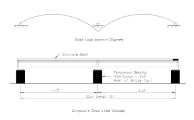
4.9.1.2. Use of Lightweight Aggregate
Another way to reduce the superstructure dead load is by using lightweight concrete. Using lightweight aggregate can reduce the typical 145 to 150 pounds per cubic foot (lb/ft3) (2,322.6 to 2,402.7 kilograms per cubic meter (kg/m3)) density of normal-weight concrete to 115 to 120 lb/ft3 (1,842.1 to 1,922.2 kg/m3) for structural lightweight concrete. Reducing the concrete density of the entire superstructure (prestressed beams, deck, barriers, etc.) could result in a reduction in dead load of nearly 20 percent that would likely reduce the required number of SPMT units and could also reduce ground compaction requirements.
Cost comparisons should be performed to determine the benefit of the reduced weight on equipment and compaction requirements versus the additional cost of the lightweight concrete. Example calculations for comparing the total bridge weight and estimated cost premium for a bridge with normal-weight concrete and lightweight concrete are in Appendix C.
4.9.2. Bridge Reuse Concepts
Frequently bridges are replaced based on increased highway capacity requirements well before they have reached their useful service life. The ability to lift and drive an entire single- or multiple-span bridge into position with SPMTs expands the potential use of bridges to more than one location. Consideration could be given in the design of bridge spans to facilitate their relocation in the future to address traffic needs more quickly and at lower cost.
Figure 6 shows a bridge reuse concept in which SPMTs are used to move two existing three-span segmental braided ramps outward onto new supports to facilitate the widening of an Interstate highway.
Figure 6: Bridge span reuse concepts-Interstate highway widening example (courtesy of FDOT)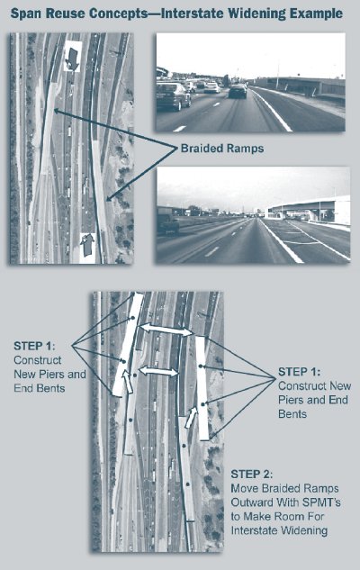
4.9.3. Other Efficiencies
Additional efficiencies are possible with the use of SPMTs to move bridges. For example, to avoid movement of bearing pads during placement of the beams on their final supports, the bearing pads can be glued or otherwise attached to the beam ends before erection onto their temporary supports at the staging area. The method of attachment must ensure that the pads will not detach during lifting and hauling to the final location.