

Composite Bridge Decking: Phase I Design Report
2. TESTING
Testing Program
The testing program consisted of an evaluation of the following:
- Materials.
- Tube subcomponents.
- Assemblies.
- Structural panels.
- Details.
Upon conclusion, the researchers provided a summary of the testing program to the project Technical Advisory Panel, and the Panel provided comments. See section 3.
Materials
Publication FHWA-HIF-12-020, Laminate Specification and Characterization, describes the FRP materials considered and tested for this project. Appendices A through C provide addenda to the Laminate Specification and Characterization report. Appendix D summarizes the testing and selection of grout material.
Tube Subcomponents
Table 1 details the testing of the tube specimens, and Appendix E presents findings of these tests.
| Test Type | No. of Specimens (10-ft span) |
Description | Purpose |
|---|---|---|---|
| 1 | 1 | Empty tube with strain gages to obtain load-deflection data. | Calibrate finite element analysis. |
| 2 | 1 | Tube filled (wide cell) with the #1 choice of grout, tested with strain gages to obtain load-deflection data. Tested wide side up. | Calibrate finite element analysis and assess performance of the bond interface. Compare performance of grouts. |
| 3 | 1 | Tube filled (narrow cell) with the #1 choice of grout, tested with strain gages to obtain load-deflection data. Tested wide side down. | Same as above but with narrow cell filled. |
| 4 | 1 | Tube filled (wide cell) with the #2 choice of grout, tested with strain gages to obtain load-deflection data. Tested wide side up. | Calibrate finite element analysis and assess performance of the bond interface. Compare performance of grouts. |
| 5 | 1 | Tube filled (narrow cell) with the #2 choice of grout, tested with strain gages to obtain load-deflection data. Tested wide side down. | Same as above but with narrow cell filled. |
| 6 | 3 | Simple deflection test of a tube filled (wide cell) with the #1 choice of grout, tested wide side up, then wide side down. | Check consistency of interface performance and relative performance of tube up vs. down. |
| 7 | 3 | Simple deflection test of a tube filled (narrow cell) with the #1 choice of grout, tested wide side up, then wide side down. | Check consistency of interface performance and relative performance of tube up vs. down. |
| 8 | 3 | Simple deflection test of a tube filled (wide cell) with the #2 choice of grout, tested wide side up, then wide side down. | Check consistency of interface performance and relative performance of tube up vs. down. |
| 9 | 3 | Simple deflection test of a tube filled (narrow cell) with the #2 choice of grout, tested wide side up, then wide side down. | Check consistency of interface performance and relative performance of tube up vs. down. |
Structural Panels
Twelve full-depth panels measuring 3 feet by 11 feet were tested to determine response under flexure, shear, and ultimate failure. The following describes the three panel types that were tested:
- Baseline: One panel type was tested without any grout to give a true indication of how much benefit is derived from the grout fill. Additionally, discussions with bridge owners revealed that they do not always need the added grout because they prefer a lighter deck. For instance, if the steel stringer spacing is only 2 feet, an unfilled panel is adequate; tight stringer spacing like this is often the case if the bridge was originally designed for 2-inch-thick timber deck. Also, there may be times when a historic bridge will always be posted for weight restriction because of the condition of the primary members. In this case a deck capable of carrying extremely heavy trucks is unwarranted. Testing determined that, in these situations, a deck can function perfectly without the addition of grout. Four panels of this type were tested in flexure.
- Top filled: Panels were tested that had grout in the top of all the tubes, similar to the original prototype. Half of the tubes had the wide cell filled and the others had the narrow cell filled. This was expected to give good plate action to the surface of the deck, helping to distribute the wheel loads. Most decks are designed as simply supported spans between stringers, so putting grout in the top portion of each tube is consistent with this approach. Two panels were made with each grout (epoxy and cementitious), resulting in a total of four panels of this type being tested in flexure.
- Alternating Grout: Conversations with the Florida DOT have highlighted the fact that decks on moveable bridges sometimes have compressive stresses in the top surface, and at other times the top surface is in tension. For example, when the span is being lifted, the stresses typically reverse. For these situations, it may be desirable to have grout in both the top and bottom of the panels so that compressive loads can be carried efficiently for either positive or negative bending. Tests were done with grout only in the wide cell, alternating between the top and bottom. Two panels were made with each grout (epoxy and cementitious), resulting in a total of four panels of this type being tested in flexure.
Documentation of the testing is presented in the following appendixes:
- Appendix F summarizes flexure testing of the structural panels as well as ultimate failure.
- Appendix G explains the short panel shear test with a concentrated load.
- Appendix H summarizes a panel fatigue test.
Assembly
Figures 1 through 7 illustrate the assembly of deck panels from tube subcomponents.
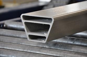
Figure 1. Photo. The pultruded tube subcomponent consisting of E-glass and vinyl ester resin.
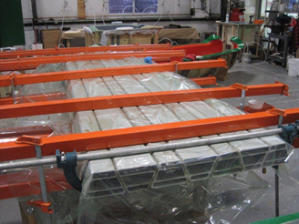
Figure 2. Photo. Tube subcomponents are bonded together with adhesive to form a panel.
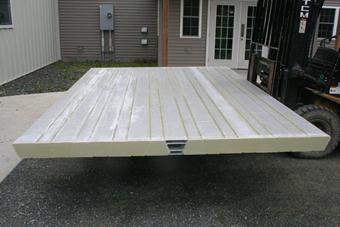
Figure 3. Photo. Panel ends are capped and radii between tubes filled with thixotropic resin.
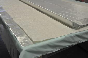
Figure 4. Photo. The panel is wrapped in glass fiber in preparation for infusion with vinyl ester resin.
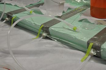
Figure 5. Photo. Resin is infused for the outer wrap using a vacuum-assisted resin transfer molding (VARTM) method.
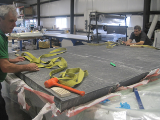
Figure 6. Photo. Each infused deck panel is stripped and inspected to ensure that fibers have been thoroughly wet-out with resin.
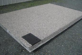
Figure 7. Photo. Adhesive and stone are applied for course 1 of the wearing surface. (The black rectangle is a bearing pad for the bridge railing post.)
Special testing categorized as “details” includes:
- Panel-to-panel field joint.
- Bridge railing anchorage.
- Connection to steel.
- Wearing surface.
- Fire testing.
Documentation of these tests is provided as follows:
- Appendix I describes the results of testing on the grouted panel-to-panel field joint.
- Appendix J describes the results of testing the bridge rail post anchorage and connections to supporting steel.
- Appendix K gives results of wearing surface pull-off tests.
Appendix L provides the laboratory report for fire testing.