U.S. Department of Transportation
Federal Highway Administration
1200 New Jersey Avenue, SE
Washington, DC 20590
202-366-4000
Federal Highway Administration Research and Technology
Coordinating, Developing, and Delivering Highway Transportation Innovations
| REPORT |
| This report is an archived publication and may contain dated technical, contact, and link information |
|
| Publication Number: FHWA-HRT-12-072 Date: May 2013 |
Publication Number: FHWA-HRT-12-072 Date: May 2013 |
Researchers studied the feasibility of equipping existing off-the-shelf pressure and humidity sensing systems with RF power-harvesting modules that would alleviate the need for wired power delivery.
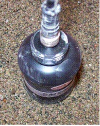
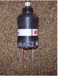
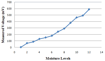
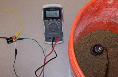
A commercial moisture cell was tested in this study. The Dynamax SM200 gauge was selected (see figure 215 and figure 216). The input voltage of the cell was between 5 and 15 V, which allows for powering using a regular 9- or 12-V battery. The output is a voltage signal varying from 0 to 1 V directly proportional to the level of moisture. This format of the output can be integrated with a wireless transmitter. Initial testing was conducted. The main objective was to test the powering scheme of the cell and identify the format of the output. The cell was attached to a 9-V battery, and the output was measured using a commercial multimeter (figure 218). Water was added gradually to a box of sand, and the output voltage was monitored as shown in figure 217. Testing showed that a commercial battery-powered RF module can be used to transmit moisture data.

Figure 215. Photo. Overhead view of Dynamax SM200 moisture gauge.

Figure 216 . Photo. Dynamax SM200 moisture gauge.

Figure 217. Graph. Measured output voltage of the moisture cell powered by a 9-V battery.

Figure 218. Photo. Testing setup for the moisture cell.
Testing showed that a commercial battery can be used to power the module and transmit the moisture data, which will eliminate the need for wires. It was also concluded that complete RF powering is not achievable using current commercially available passive modules. The depth at which these gauges are to be embedded causes the RF wave to attenuate to levels below the required minimum power. The non-feasibility of a completely continuous RF powered module will not affect the long-term monitoring performance for the purpose of fatigue prediction. Time snapshots of moisture and subgrade pressure levels can be still acquired and used.