

Precast Bent System for High Seismic Regions: Laboratory Tests of Column-to-Drilled Shaft Socket Connections
APPENDIX B: MATERIAL TESTS
Concrete Strengths
Both specimen DS-1 and DS-2 used the common concrete mix with code 09468 provided by Calportland Company. The concrete design strength was 6,000 psi. It used 3/8-inch aggregate pea gravel and had a specified slump of 5 inches.
The concrete compressive strength at 7, 14, and 28 days are provided in the following table.
Time |
7-Day (psi) |
14-Day (psi) |
28-Day (psi) |
Day of Test (psi) |
|---|---|---|---|---|
| DS1 Column | 5130 | 5820 | 6250 | 7770 |
| DS1 Shaft | 5320 | 6350 | 6600 | 7360 |
| DS2 Column | 4780 | 6350 | 6600 | 7170 |
| DS2 Shaft | 5270 | 5790 | 6400 | 6450 |
Reinforcement
Reinforcement used in the footing and column conformed to ASTM standard 706. The column spiral used the three-gauge wire (0.244-inch diameter), which was the same as that used by Haraldsson and Janes.(10,14) The shaft spiral used the 9-gauge wire (0.148-inch diameter). All spirals conformed to ASTM A82.
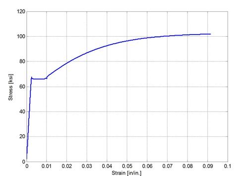
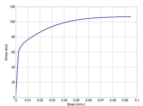
The tension tests were performed using the MTS system machine, and the elongation was measured by an extensometer. The tension specimen was loaded slowly until the load reached its maximum and started decreasing. The extensometer was then removed to prevent damage to the equipment. The specimen was then loaded to failure, after which the length was measured to obtain a strain at failure.
Results of the tension tests for bars No. 3 and No. 5 are shown in figures 82 and 83. Because the spirals were too small and extensometer cannot be used to measure the elongation, only the ultimate stresses of spirals were found. These are reported in table 10.
|
9-gauge wire (psi) |
3-gauge wire (psi) |
|---|---|
| 109,860 | 95,050 |