

Precast Bent System for High Seismic Regions: Laboratory Tests of Column-to-Drilled Shaft Socket Connections
APPENDIX C: DAMAGE PROGESSION
Specimen DS-1
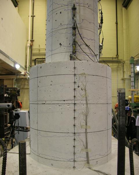
Figure 84. Photo. Specimen DS-1 - significant horizontal crack in cycle 4-1
(0.56/-0.75 percent drift).
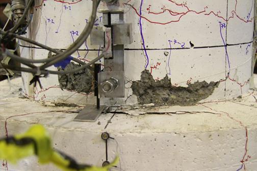
Figure 85. Photo. Specimen DS-1 - first significant spalling occurred in the column
in cycle 7-2 (3.00/-3.14 percent drift).
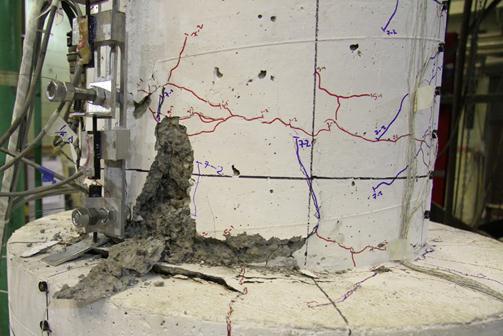
Figure 86. Photo. Specimen DS-1 - plastic hinge formed in the column in cycle 8-3
(4.60/-4.68 percent drift).
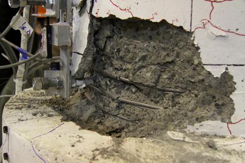
Figure 87. Photo. Specimen DS-1 - first noticeable bar buckling in the column in cycle 9-3 (6.90/-6.81 percent drift).
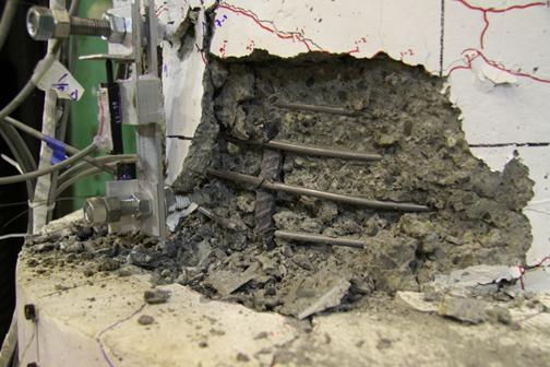
Figure 88. Photo. Specimen DS-1 - first column spiral fractured in cycle 10-1
(8.43/-8.27 percent drift).
Specimen DS-2
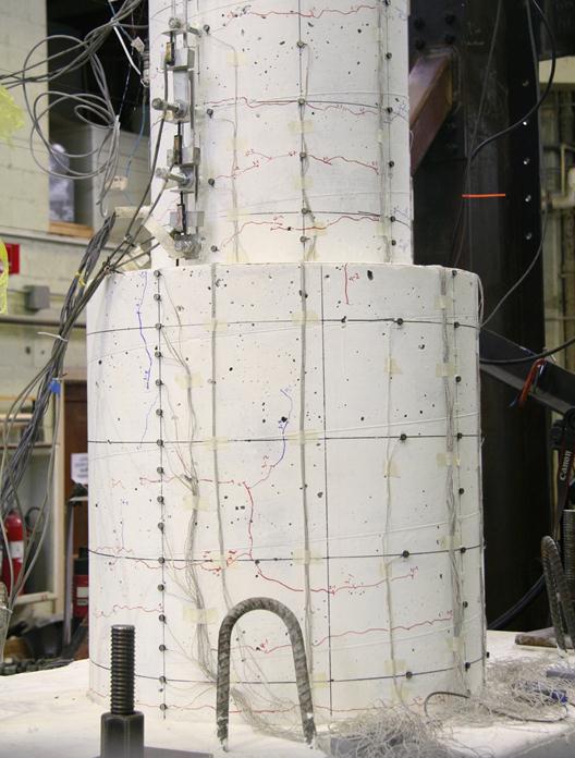
Figure 91. Photo. Specimen DS-2 - significant horizontal crack in cycle 4-2
(0.73/-0.87 percent drift).
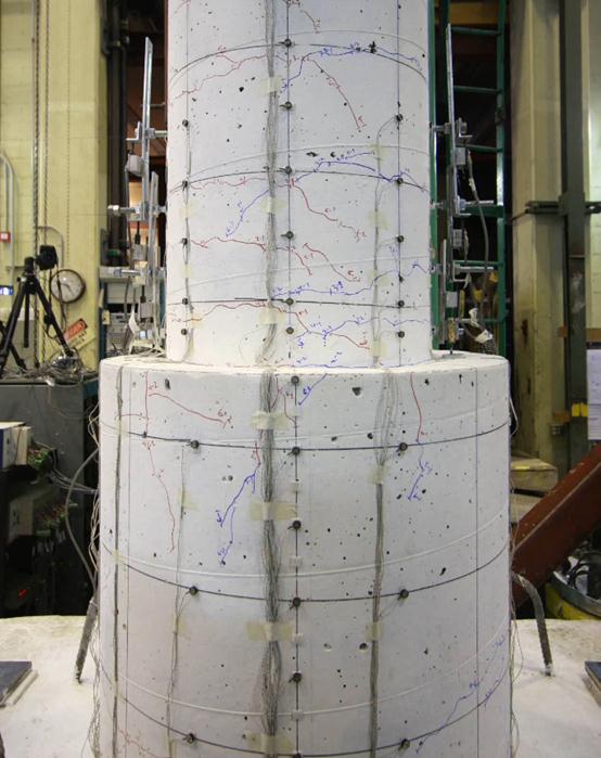
Figure 92. Photo. Specimen DS-2 - first diagonal crack in the shaft in cycle 6-2
(1.87/-2.02 percent drift).
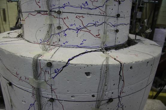
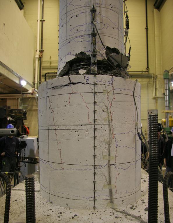
Figure 93. Photo. Specimen DS-2 - shaft damage when first shaft spiral fractured
in cycle 8-2 (4.59/-4.59 percent drift).
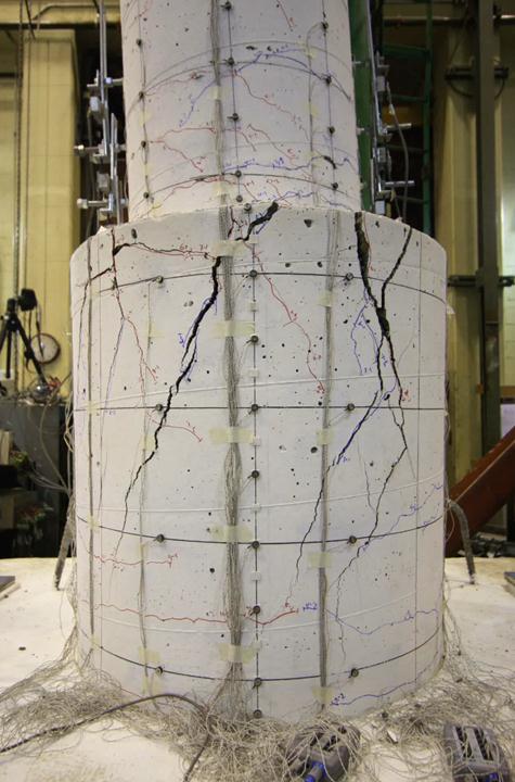
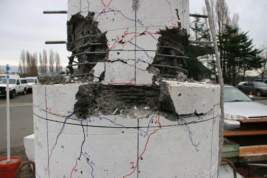
Figure 94. Photo. Specimen DS-2 - first noticeable prying action in shaft
in cycle 9-2 (6.72/-6.83 percent drift).
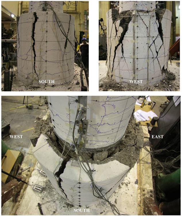
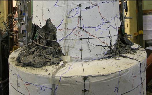
Figure 95. Photos. Specimen DS-2 shaft damage after cyclic testing.
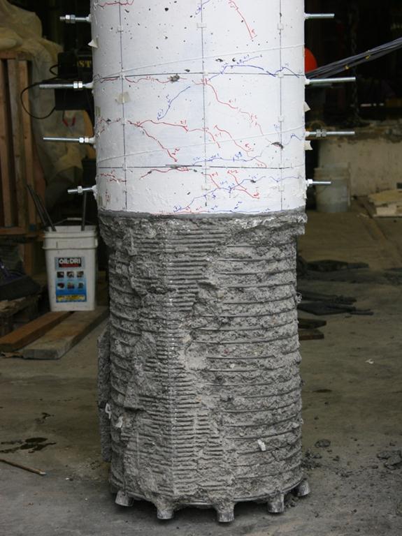
Figure 96. Photo. Specimen DS-2 column damage after cyclic testing.