U.S. Department of Transportation
Federal Highway Administration
1200 New Jersey Avenue, SE
Washington, DC 20590
202-366-4000
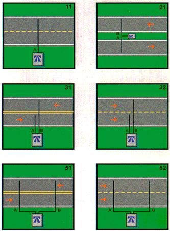
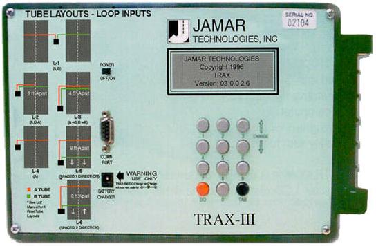
A Summary of Vehicle Detection and Surveillance Technologies use in Intelligent Transportation SystemsChapter 4 - In-roadway Sensor TechnologiesIn-roadway sensors are those requiring installation on, embedded in, or installation below the road surface. The pneumatic road tube, inductive loop detector, magnetic sensors, piezoelectric cable, and weigh-in-motion sensors (piezoelectric, bending plate, load cell, and capacitance mat) are examples of in-roadway sensors, which are discussed in the following sections. PNEUMATIC ROAD TUBEPrinciples of OperationPneumatic road tube sensors send a burst of air pressure along a rubber tube when a vehicle's tires pass over the tube. The pressure pulse closes an air switch, producing an electrical signal that is transmitted to a counter or analysis software. The pneumatic road tube sensor is portable, using lead-acid, gel, or other rechargeable batteries as a power source. Applications and UsesThe road tube is installed perpendicular to the traffic flow direction and is commonly used for short-term traffic counting, vehicle classification by axle count and spacing, planning, and research studies. Some models gather data to calculate vehicle gaps, intersection stop delay, stop sign delay, saturation flow rate, spot speed as a function of vehicle class, and travel time when the counter is utilized in conjunction with a vehicle transmission sensor (JAMAR Technologies). AdvantagesAdvantages of road tube sensors are quick installation for permanent and temporary recording of data and low power usage. Road tube sensors are usually low cost and simple to maintain. Sensor manufacturers often supply software packages to assist with data analysis. DisadvantagesDisadvantages include inaccurate axle counting when truck and bus volumes are high, temperature sensitivity of the air switch, and cut tubes from vandalism and truck tire wear. Installation ConfigurationFigure 2 shows some of the road tube configurations utilized on single and multilane highways to count and classify vehicles. Figure 3 displays the front panel of the JAMAR TRAX-III counter, which indicates how data analysis parameters are selected to match the tube layout.
Figure 2. Road tube configurations for single and multilane highways. (Photograph courtesy of Time Mark, Inc., Salem , OR ).
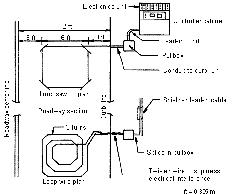
Figure 3. Front panel display of JAMAR TRAX -III counter. (Photograph courtesy of Jamar Technologies, Inc., Horsham , PA ). MANUFACTURER AND VENDOR INFORMATION Effective Date: March 22, 2000 Manufacturer name: International Road Sales representative name(s): Dynamics Inc. (IRD) Rod Klashinsky Address: 702 43rd St. East Address: Saskatoon SK , S7K 3T9 CANADA Phone number: 306-653-6600 Phone number: Fax number: 306-242-5599 Fax number: e-mail address: info@ird.ca e-mail address: rod.klashinsky@ird.caemail@domain_name_here.com URL address: www.irdinc.com URL address: PRODUCT NAME/MODEL NUMBER: Model TCC540 Traffic Counter Classifier FIRMWARE VERSION/CHIP NO.: V2.6 SOFTWARE VERSION NO.: V4.73 GENERAL DESCRIPTION OF EQUIPMENT: Portable or permanent battery operated multi-lane time interval recording counter & classifier that collects traffic data SENSOR TECHNOLOGY AND CONFIGURATION: Uses road Tube, Inductive Loops, Piezoelectric sensors, IRD Dynax® Sensor. Most common configuration is Loop-Piezo-Loop configuration SENSOR INSTALLATION: Portable (On road) Permanent (In road) INSTALLATION TIME (Per Lane ): Approximately 4-5 hours in a permanent Loop-Piezo-Loop configuration. Approximately 15-20 minutes in a portable application. INSTALLATION REQUIREMENTS: See attached Installation sheet. MAXIMUM NUMBER OF LANES MONITORED SIMULTANEOUSLY: 8 lanes classifying, 16 lanes counting. PRODUCT CAPABILITIES/FUNCTIONS: Collects vehicle traffic data, including vehicle classification, speed, volume, headway and gap. RECOMMENDED APPLICATIONS: Traffic Planning, Traffic Profile, Safety, and Audit. POWER REQUIREMENTS (watts/amps): AC Power for 6 volt, 12 amp rechargeable battery. POWER OPTIONS: Dual battery units, solar package. CLASSIFICATION ALGORITHMS: See attached specifications. TELEMETRY: RS232 port with baud rates from 300 to 19,2000. COMPUTER REQUIREMENTS: MSDOS. DATA OUTPUT: IBM PC, Modem, Take-Away-Memory (TAM) DATA OUTPUT FORMATS: SUPPORTING DATA BASE MANAGEMENT SYSTEM: Trafman® Software EQUIPMENT AND INSTALLATION COSTS (One-lane and four-lane): Permanent One lane - Approx. US $5,000; 4 lanes - Approx. US $9,000. STATES CURRENTLY USING THIS EQUIPMENT: Country/State Contact name Telephone number USA/New Jersey Canada/Saskatchewan Canada/Manitoba Canada/Ontario Canada/Quebec Canada/Nova Scotia Canada/New Brunswick Canada/Newfoundland. Brazil Uruguay Venezuela Columbia India . MANUFACTURER AND VENDOR INFORMATION Effective Date: March 22, 2000 Manufacturer name: International Road Sales representative name(s): Dynamics Inc. (IRD) Rod Klashinsky Address: 702 43rd St. East Address: Saskatoon SK , S7K 3T9 CANADA Phone number: 306-653-6600 Phone number: Fax number: 306-242-5599 Fax number: e-mail address: info@ird.ca e-mail address: rod.klashinsky@ird.ca URL address: www.irdinc.com URL address: PRODUCT NAME/MODEL NUMBER: Model AS4XX Dynax® Treadle Systems FIRMWARE VERSION/CHIP NO.: N/A SOFTWARE VERSION NO.: N/A GENERAL DESCRIPTION OF EQUIPMENT: Speed independent axle sensing systems. SENSOR TECHNOLOGY AND CONFIGURATION: Pressure sensitive activation. Set in frame, using 1, 2, 3 or 4 sensors SENSOR INSTALLATION: Frame and Treadle system are permanent, sensor installation or replacement, less than 20 minutes. INSTALLATION TIME (Per Lane ): 4-5 hours for Frame and Treadle systems; 20 minutes for sensors. INSTALLATION REQUIREMENTS: Contact IRD for information. MAXIMUM NUMBER OF LANES MONITORED SIMULTANEOUSLY: One treadle per lane (from stop and go traffic to 100 miles per hour). PRODUCT CAPABILITIES/FUNCTIONS: Classification of vehicles by number of axles detected. RECOMMENDED APPLICATIONS: Toll plaza POWER REQUIREMENTS (watts/amps): 12 volts DC (±5%) POWER OPTIONS: With voltage regulator between 15 VDC to 28 VDC CLASSIFICATION ALGORITHMS: N/A (axle sensor output activation only) TELEMETRY: N/A COMPUTER REQUIREMENTS: DATA OUTPUT: B-420-4-A Dynax® Interface Circuit Board outputs sensor activation only. DATA OUTPUT FORMATS: SUPPORTING DATA BASE MANAGEMENT SYSTEM: Customers own data base EQUIPMENT AND INSTALLATION COSTS (One-lane and four-lane): Installation and equipment costs for 1 sensor, 8 ft systems - US $6,500. For 4 sensors, 10 ft system - US $8,500. STATES CURRENTLY USING THIS EQUIPMENT: Country/State USA/California USA/Colorado USA/Delaware USA/Florida USA/Maine USA/Michigan USA / New York USA/New Jersey USA/Oklahoma USA/Texas USA/Virginia Canada/Nova Scotia Canada/New Brunswick Brazil Columbia Uruguay India . MANUFACTURER AND VENDOR INFORMATION Effective Date: March 1, 2000 Manufacturer name: Sales representative name(s): Traffic Monitoring Technologies Donald Dixon Address: Address: 6510 Chantilly Drive , 1st Floor 6510 Chantilly Drive, 1st Floor Sykesville , Maryland 21784-8100 Sykesville , Maryland 21784-8100 Phone number: (410) 549-8779 Phone number: (410) 549-8779 Fax number: (410) 549-5113 Fax number: (410) 549-5113 e-mail address: tmt@erols.com e-mail address: tmt@erols.com URL address: trafficmonitoring.com URL address: trafficmonitoring.com PRODUCT NAME/MODEL NUMBER: The Blocker FIRMWARE VERSION/CHIP NO.: SOFTWARE VERSION NO.: GENERAL DESCRIPTION OF EQUIPMENT: A cover and protector for low-profile or mini road tube and the lead-in cable for electronic sensors. It incorporates a tough and durable polymer that is flexible enough to contour the road, yet strong enough to prevent vehicles from compressing it. Used to obtain multi-lane volume/speed/class counts and WIM data from interior lanes. SENSOR TECHNOLOGY AND CONFIGURATION: SENSOR INSTALLATION: The Blocker is placed over the road tube leading cable and taped to the road to prevent movement. INSTALLATION TIME (Per Lane ): 2-5 minutes INSTALLATION REQUIREMENTS: Road tape, dry conditions MAXIMUM NUMBER OF LANES MONITORED SIMULTANEOUSLY: The Blocker comes in 6 ft lengths, can be placed end-to-end to cover unlimited number of lanes. PRODUCT CAPABILITIES/FUNCTIONS: Prevents vehicles from predicting in road tube and protects lead-in cables of electronic sensors so counts and WIM data can be collected from interior lanes. RECOMMENDED APPLICATIONS: Where multiple lanes of data are needed and the road tube or sensor must cross lanes with vehicular traffic. Also used to block out turn lanes for intersection studies. POWER REQUIREMENTS (watts/amps): None POWER OPTIONS: None CLASSIFICATION ALGORITHMS: N/A TELEMETRY: N/A COMPUTER REQUIREMENTS: N/A DATA OUTPUT: N/A DATA OUTPUT FORMATS: N/A SUPPORTING DATA BASE MANAGEMENT SYSTEM: N/A EQUIPMENT AND INSTALLATION COSTS (One-lane and four-lane): $138 per lane, the Blocker is portable and can be used again and again over several applications STATES CURRENTLY USING THIS EQUIPMENT: Country/State Contact name Telephone number USA/PETCORP ( Maryland ) John Reed (410) 381-1995 USA/STS ( Florida ) Mark Knowles (800) 786-3374 USA /The Traffic Group Anthony Zuckert (410) 931-6600 USA/Traffic Data Services Ryan (800) 837-2562 MANUFACTURER AND VENDOR INFORMATION Effective Date: 2/22/2000 Manufacturer name: Sales representative name(s): TimeMark Inc. Mike Bonser , Kerry Penn , Tim Miner Address: P.O. Box 12947 Address: Salem , OR 97309-0947 Phone number: (800) 755-5882 or (503) 363-2012 Phone number: Fax number: (503) 363-1716 Fax number: e-mail address: sales@timemarkinc.com e-mail address: URL address: URL address: PRODUCT NAME/MODEL NUMBER: Delta 111B & Delta 111L FIRMWARE VERSION/CHIP NO.: 1.02 SOFTWARE VERSION NO.: 3.2.7 GENERAL DESCRIPTION OF EQUIPMENT: 4 tube counter, classifier SENSOR TECHNOLOGY AND CONFIGURATION: Road tube SENSOR INSTALLATION: Road tube hardware INSTALLATION TIME (Per Lane ): 5 min. INSTALLATION REQUIREMENTS: MAXIMUM NUMBER OF LANES MONITORED SIMULTANEOUSLY: Four PRODUCT CAPABILITIES/FUNCTIONS: Bi-directional volume, speed, axle classification, gap - all with one setting of counter under 5,000 ADT - volume counts on 4 lanes of traffic simultaneously RECOMMENDED APPLICATIONS: 2 lane - same way or bi-directional 5,000 A.D.T. and above. 4 lane roadways for volume POWER REQUIREMENTS (watts/amps): POWER OPTIONS: 60 day rechargeable gel cell battery CLASSIFICATION ALGORITHMS: TELEMETRY: If needed COMPUTER REQUIREMENTS: 486 or better - Win 95, 98, NT DATA OUTPUT: DATA OUTPUT FORMATS: Comma delimited, strecter, TAS plus, GK and others as needed SUPPORTING DATA BASE MANAGEMENT SYSTEM: EQUIPMENT AND INSTALLATION COSTS (One-lane and four-lane): $1,950.00 STATES CURRENTLY USING THIS EQUIPMENT: Country/State Contact name Telephone number Please contact Timemark Inc. for current list of references. MANUFACTURER AND VENDOR INFORMATION Effective Date: 2/22/2000 Manufacturer name: Sales representative name(s): TimeMark Inc. Mike Bonser , Kerry Penn , Tim Miner Address: P.O. Box 12947 Address: Salem , OR 97309-0947 Phone number: (800) 755-5882 or (503) 363-2012 Phone number: Fax number: (503) 363-1716 Fax number: e-mail address: sales@timemarkinc.com e-mail address: URL address: URL address: PRODUCT NAME/MODEL NUMBER: Gamma FIRMWARE VERSION/CHIP NO.: 1.02 SOFTWARE VERSION NO.: 3.2.7 GENERAL DESCRIPTION OF EQUIPMENT: Two tube counter/classifier SENSOR TECHNOLOGY AND CONFIGURATION: Road tube SENSOR INSTALLATION: Road tube hardware INSTALLATION TIME (Per Lane ): 5 minutes INSTALLATION REQUIREMENTS: MAXIMUM NUMBER OF LANES MONITORED SIMULTANEOUSLY: Two PRODUCT CAPABILITIES/FUNCTIONS: Bi-directional volume, speed, axle classification, gap - all with one setting of counter under 5,000 ADT RECOMMENDED APPLICATIONS: 2 lane - same way or bi-directional roadways POWER REQUIREMENTS (watts/amps): POWER OPTIONS: 90 day rechargeable gel cell battery CLASSIFICATION ALGORITHMS: TELEMETRY: COMPUTER REQUIREMENTS: 486 or better - Win 95, 98, NT DATA OUTPUT: DATA OUTPUT FORMATS: Comma delimited, strecter, TAS plus, GK and others as needed SUPPORTING DATA BASE MANAGEMENT SYSTEM: EQUIPMENT AND INSTALLATION COSTS (One-lane and four-lane): $1,650.00 STATES CURRENTLY USING THIS EQUIPMENT: Country/State Contact name Telephone number Please contact Timemark Inc. for current list of references. INDUCTIVE LOOP DETECTORSThe inductive loop detector (ILD) is the most common sensor used in traffic management applications. Its size and shape vary, including the 5-ft by 5-ft or 6-ft by 6-ft square loops, 6-ft diameter round loops, and rectangular configurations having a 6-ft width and variable length ( Klein , et al., 2006). Figure 4 shows the principal components of an inductive loop detector: one or more turns of insulated wire buried in a shallow sawcut in the roadway, a lead-in cable that runs from a roadside pull box to the controller cabinet, and an electronics unit located in the controller cabinet.
Figure 4. Principal components of an inductive loop detector installation. Principles of OperationThe wire loop is excited with signals whose frequencies range from 10 KHz to 50 KHz and above. The loop functions as an inductive element in conjunction with the electronics unit. When a vehicle stops on or passes over the loop, the inductance of the loop is decreased. The decreased inductance increases the oscillation frequency and causes the electronics unit to send a pulse to the controller, indicating the presence or passage of a vehicle. Applications and UsesThe data supplied by conventional inductive loop detectors are vehicle passage, presence, count, and occupancy. Although loops cannot directly measure speed, speed can be determined using a two-loop speed trap or a single loop detector and an algorithm whose inputs are loop length, average vehicle length, time over the detector, and number of vehicles counted. Vehicle classification is supported by newer versions of the inductive loop containing electronics units that excite the wire loop at the higher frequencies that identify specific metal portions under the vehicle. AdvantagesThe operation of inductive loop sensors is well understood and their application for providing basic traffic parameters (volume, presence, occupancy, speed, headway, and gap) represents a mature technology. As was the case with the pneumatic road tube, the equipment cost of inductive loop sensors may be low when compared to over-roadway sensors. Another advantage of inductive loop sensors is their suitability for a large variety of applications due to their flexible design. DisadvantagesThe drawbacks of inductive loop detectors include disruption of traffic for installation and repair, and failures associated with installations in poor road surfaces and use of substandard installation procedures. In addition, resurfacing of roadways and utility repair can also create the need to reinstall these types of sensors. The wire loops are also subject to the stresses of traffic and temperature. Therefore, installation and maintenance costs significantly increase the life-cycle cost of inductive loop detectors. In many instances multiple detectors are required to instrument a location. MANUFACTURER AND VENDOR INFORMATION Effective Date: April 10, 2007 Manufacturer name: Sales representative name(s): Never Fail Loop Systems. Roland Smits Address: 7911 NE 33rd Drive , Unit 160 Address: Same Portland , OR 97211 Phone number: (503) 408-9248 Phone number Fax number: (503) 408-1032 Fax number: e-mail address: sales@neverfail.com e-mail address: roland@neverfail.com URL address: www.neverfail.com URL address: PRODUCT NAME/MODEL NUMBER: Models A (asphalt overlay), C (concrete overlay), F (cut-in application), F-38 (all previous, plus temporary) FIRMWARE VERSION/CHIP NO.: N/A SOFTWARE VERSION NO.: N/A GENERAL DESCRIPTION OF EQUIPMENT: Preformed Traffic Detection Loops SENSOR TECHNOLOGY AND CONFIGURATION: Inductive Loops SENSOR INSTALLATION: In-ground INSTALLATION TIME (Per Lane ): New pavement applications 10 minutes, existing pavement approximately 1 hour INSTALLATION REQUIREMENTS: MAXIMUM NUMBER OF LANES MONITORED SIMULTANEOUSLY: No maximum PRODUCT CAPABILITIES/FUNCTIONS: Traffic control, preemption, volume count, speed count, intersection control, traffic jam detection RECOMMENDED APPLICATIONS: Intersections, freeways POWER REQUIREMENTS (watts/amps): N/A POWER OPTIONS: N/A CLASSIFICATION ALGORITHMS: N/A TELEMETRY: N/A COMPUTER REQUIREMENTS: N/A DATA OUTPUT: DATA OUTPUT FORMATS: SUPPORTING DATA BASE MANAGEMENT SYSTEM: EQUIPMENT AND INSTALLATION COSTS (One-lane and four-lane): STATES CURRENTLY USING THIS EQUIPMENT: Country/State Contact name Telephone number Please contact Neverfail Loop Systems for current list of references. MANUFACTURER AND VENDOR INFORMATION Effective Date: 4/23/07 Manufacturer name: Peek Traffic Corp. Sales representative name(s): Joyce Turco Address: 2511 Corporate Way Address: same Palmetto , Florida 34221 Phone number: (941) 845-1200 Phone number: Fax number: (941) 365-0837 Fax number: e-mail address: joyce.turco@quixotecorp.com URL address: www.peektrafficinc.com/products URL address: PRODUCT NAME/MODEL NUMBER: 222GP6 FIRMWARE VERSION/CHIP NO.: SOFTWARE VERSION NO.: GENERAL DESCRIPTION OF EQUIPMENT: 2-channel inductive loop detector. SENSOR TECHNOLOGY AND CONFIGURATION: Monitors the change of inductance produced by a metal vehicle passing over a wire loop SENSOR INSTALLATION: Plug-in module, plugs into card rack INSTALLATION TIME (Per Lane ): Minimal INSTALLATION REQUIREMENTS: Must be connected to in-ground inductive loop MAXIMUM NUMBER OF LANES/LOOPS MONITORED SIMULTANEOUSLY: Two PRODUCT CAPABILITIES/FUNCTIONS: Monitors wire loop for inductance changes. Outputs on passage of vehicle over buried loop of wire. RECOMMENDED APPLICATIONS: Both intersection and freeway control with 170 and 2070 controllers. Used in traffic signal systems. POWER REQUIREMENTS (watts/amps): 10.8 to 28.8 VDC, 80 mA maximum POWER OPTIONS: CLASSIFICATION ALGORITHMS: TELEMETRY: COMPUTER REQUIREMENTS: DATA OUTPUT: DATA OUTPUT FORMATS: SUPPORTING DATA BASE MANAGEMENT SYSTEM: EQUIPMENT AND INSTALLATION COSTS (One-lane and four-lane): STATES CURRENTLY USING THIS EQUIPMENT: Country/State Contact name Telephone number USA/California Bob McMillan (916) 654-4385 USA / New York Mike Naumiec (518) 783-7746 MANUFACTURER AND VENDOR INFORMATION Effective Date: 4/23/07 Manufacturer name: Peek Traffic Corp. Sales representative name(s): Joyce Turco Address: 2511 Corporate Way Address: same Palmetto , Florida 34221 Phone number: (941) 845-1200 Phone number: Fax number: (941) 365-0837 Fax number: e-mail address: e-mail address: joyce.turco@quixotecorp.com URL address: www.peektrafficinc.com/products URL address: PRODUCT NAME/MODEL NUMBER: 222T GP7 FIRMWARE VERSION/CHIP NO.: SOFTWARE VERSION NO.: GENERAL DESCRIPTION OF EQUIPMENT: Two-channel inductive loop detector. With extend and delay timers. For TS-1 and TS-2 SENSOR TECHNOLOGY AND CONFIGURATION: Monitors the change of inductance produced by a metal vehicle passing over a wire loop SENSOR INSTALLATION: Plug-in module, plugs into card rack INSTALLATION TIME (Per Lane ): Minimal INSTALLATION REQUIREMENTS: Must be connected to in-ground inductive loop MAXIMUM NUMBER OF LANES/LOOPS MONITORED SIMULTANEOUSLY: Two PRODUCT CAPABILITIES/FUNCTIONS: Monitors wire loop for inductance changes. Outputs on passage of vehicle over buried loop of wire. RECOMMENDED APPLICATIONS: Intersection and freeway control. Used in traffic signal systems. POWER REQUIREMENTS (watts/amps): 10 - 30 VDC POWER OPTIONS: CLASSIFICATION ALGORITHMS: TELEMETRY: COMPUTER REQUIREMENTS: DATA OUTPUT: DATA OUTPUT FORMATS: SUPPORTING DATA BASE MANAGEMENT SYSTEM: EQUIPMENT AND INSTALLATION COSTS (One-lane and four-lane): STATES CURRENTLY USING THIS EQUIPMENT: Country/State Contact name Telephone number Please contact Peek Traffic for current list of references. MANUFACTURER AND VENDOR INFORMATION Effective Date: 4/23/07 Manufacturer name: Peek Traffic Corp. Sales representative name(s): Joyce Turco Address: 2511 Corporate Way Address: same Palmetto , Florida 34221 Phone number: (941) 845-1200 Phone number: Fax number: (941) 365-0837 Fax number: e-mail address: e-mail address: joyce.turco@quixotecorp.com URL address: www.peektrafficinc.com/products URL address: PRODUCT NAME/MODEL NUMBER: 222 GP7 FIRMWARE VERSION/CHIP NO.: SOFTWARE VERSION NO.: GENERAL DESCRIPTION OF EQUIPMENT: 2-channel inductive loop detector. For TS-1 and TS-2 SENSOR TECHNOLOGY AND CONFIGURATION: Monitors the change of inductance produced by a metal vehicle passing over a wire loop SENSOR INSTALLATION: Plug in module, plugs into card rack INSTALLATION TIME (Per Lane ): Minimal INSTALLATION REQUIREMENTS: Must be connected to in-ground inductive loop MAXIMUM NUMBER OF LANES/LOOPS MONITORED SIMULTANEOUSLY: Two PRODUCT CAPABILITIES/FUNCTIONS: Monitors wire loop for inductance changes. Outputs on passage of vehicle over buried loops of wire. RECOMMENDED APPLICATIONS: Intersection and freeway control. Used in traffic signal systems. POWER REQUIREMENTS (watts/amps): 10 - 30 VDC POWER OPTIONS: CLASSIFICATION ALGORITHMS: TELEMETRY: COMPUTER REQUIREMENTS: DATA OUTPUT: DATA OUTPUT FORMATS: SUPPORTING DATA BASE MANAGEMENT SYSTEM: EQUIPMENT AND INSTALLATION COSTS (One-lane and four-lane): STATES CURRENTLY USING THIS EQUIPMENT: Country/State Contact name Telephone number Please contact Peek Traffic for current list of references. MANUFACTURER AND VENDOR INFORMATION Effective Date: 4/23/07 Manufacturer name: Peek Traffic Corp. Sales representative name(s): Joyce Turco Address: 2511 Corporate Way Address: same Palmetto , Florida 34221 Phone number: (941) 845-1200 Phone number: Fax number: (941) 365-0837 Fax number: e-mail address: e-mail address: joyce.turco@quixotecorp.com URL address: www.peektrafficinc.com/products URL address: PRODUCT NAME/MODEL NUMBER: 224 GP5 FIRMWARE VERSION/CHIP NO.: SOFTWARE VERSION NO.: GENERAL DESCRIPTION OF EQUIPMENT: 4-channel inductive loop detector. SENSOR TECHNOLOGY AND CONFIGURATION: Monitors the change of inductance produced by a metal vehicle passing over a wire loop SENSOR INSTALLATION: Plug in module, plugs into card rack INSTALLATION TIME (Per Lane ): Minimal INSTALLATION REQUIREMENTS: Must be connected to in-ground inductive loop MAXIMUM NUMBER OF LANES/LOOPS MONITORED SIMULTANEOUSLY: Four PRODUCT CAPABILITIES/FUNCTIONS: Monitors wire loop for inductive changes. Outputs on passage of vehicle over buried loop of wire. RECOMMENDED APPLICATIONS: Intersection and freeway control. Used in traffic signal systems. POWER REQUIREMENTS (watts/amps): 10.8 to 28.8 VDC, 80 mA maximum POWER OPTIONS: CLASSIFICATION ALGORITHMS: TELEMETRY: COMPUTER REQUIREMENTS: DATA OUTPUT: DATA OUTPUT FORMATS: SUPPORTING DATA BASE MANAGEMENT SYSTEM: EQUIPMENT AND INSTALLATION COSTS (One-lane and four-lane): STATES CURRENTLY USING THIS EQUIPMENT: Country/State Contact name Telephone number USA/California Bob McMillan (916) 654-4385 USA / New York Mike Naumiec (518) 783-7746 MANUFACTURER AND VENDOR INFORMATION Effective Date: 4/23/07 Manufacturer name: Peek Traffic Corp. Sales representative name(s): Joyce Turco Address: 2511 Corporate Way Address: same Palmetto , Florida 34221 Phone number: (941) 845-1200 Phone number: Fax number: (941) 365-0837 Fax number: e-mail address: e-mail address: joyce.turco@quixotecorp.com URL address: www.peektrafficinc.com/products URL address: PRODUCT NAME/MODEL NUMBER: 224 GP7 FIRMWARE VERSION/CHIP NO.: SOFTWARE VERSION NO.: GENERAL DESCRIPTION OF EQUIPMENT: 4-channel inductive loop detector. For TS-1 and TS-2 SENSOR TECHNOLOGY AND CONFIGURATION: Monitors the change of inductance produced by a metal vehicle passing over a wire loop SENSOR INSTALLATION: Plug in module, plugs into card rack INSTALLATION TIME (Per Lane ): Minimal INSTALLATION REQUIREMENTS: Must be connected to in-ground inductive loop MAXIMUM NUMBER OF LANES/LOOPS MONITORED SIMULTANEOUSLY: Four PRODUCT CAPABILITIES/FUNCTIONS: Monitors wire loop for inductance changes. Outputs on passage of vehicle over buried loops of wire. RECOMMENDED APPLICATIONS: Intersection and freeway control. Used in traffic signal systems. POWER REQUIREMENTS (watts/amps): 10 to 30 VDC POWER OPTIONS: CLASSIFICATION ALGORITHMS: TELEMETRY: COMPUTER REQUIREMENTS: DATA OUTPUT: DATA OUTPUT FORMATS: SUPPORTING DATA BASE MANAGEMENT SYSTEM: EQUIPMENT AND INSTALLATION COSTS (One-lane and four-lane): STATES CURRENTLY USING THIS EQUIPMENT: Country/State Contact name Telephone number Please contact Peek Traffic for current list of references. MANUFACTURER AND VENDOR INFORMATION Effective Date: 4/23/07 Manufacturer name: Peek Traffic Corp. Sales representative name(s): Joyce Turco Address: 2511 Corporate Way Address: same Palmetto , Florida 34221 Phone number: (941) 845-1200 Phone number: Fax number: (941) 365-0837 Fax number: e-mail address: e-mail address: joyce.turco@quixotecorp.com URL address: www.peektrafficinc.com/products URL address: PRODUCT NAME/MODEL NUMBER: 224T GP7 FIRMWARE VERSION/CHIP NO.: SOFTWARE VERSION NO.: GENERAL DESCRIPTION OF EQUIPMENT: 4-channel inductive loop detector. With extend and delay timers. For TS-1 and TS-2 SENSOR TECHNOLOGY AND CONFIGURATION: Monitors the change of inductance and frequency SENSOR INSTALLATION: Plug-in module, plugs into card rack INSTALLATION TIME (Per Lane ): Minimal INSTALLATION REQUIREMENTS: Must be connected to in-ground inductive loop MAXIMUM NUMBER OF LANES/LOOPS MONITORED SIMULTANEOUSLY: Four PRODUCT CAPABILITIES/FUNCTIONS: Monitors wire loop for inductance changes. Outputs on passage of vehicle over buried loop of wire. RECOMMENDED APPLICATIONS: Intersection and freeway control. Used in traffic signal systems. POWER REQUIREMENTS (watts/amps): 10 - 30 VDC POWER OPTIONS: CLASSIFICATION ALGORITHMS: TELEMETRY: COMPUTER REQUIREMENTS: DATA OUTPUT: DATA OUTPUT FORMATS: SUPPORTING DATA BASE MANAGEMENT SYSTEM: EQUIPMENT AND INSTALLATION COSTS (One-lane and four-lane): STATES CURRENTLY USING THIS EQUIPMENT: Country/State Contact name Telephone number Please contact Peek Traffic for current list of references. MANUFACTURER AND VENDOR INFORMATION Effective Date: 4/23/07 Manufacturer name: Peek Traffic Corp. Sales representative name(s): Joyce Turco Address: 2511 Corporate Way Address: same Palmetto , Florida 34221 Phone number: (941) 845-1200 Phone number: Fax number: (941) 365-0837 Fax number: e-mail address: e-mail address: joyce.turco@quixotecorp.com URL address: www.peektrafficinc.com/products URL address: PRODUCT NAME/MODEL NUMBER: 535B/MS GP7 FIRMWARE VERSION/CHIP NO.: SOFTWARE VERSION NO.: GENERAL DESCRIPTION OF EQUIPMENT: 1 channel inductive loop detector. SENSOR TECHNOLOGY AND CONFIGURATION: Monitors the change of inductance produced by a metal vehicle passing over a wire loop SENSOR INSTALLATION: Shelf mount INSTALLATION TIME (Per Lane ): Minimal INSTALLATION REQUIREMENTS: Must be connected to in-ground inductive loop MAXIMUM NUMBER OF LANES/LOOPS MONITORED SIMULTANEOUSLY: One PRODUCT CAPABILITIES/FUNCTIONS: Monitors wire loop for inductive changes. Outputs on passage of vehicle over buried loop of wire. RECOMMENDED APPLICATIONS: Intersection and freeway control. Used in traffic signal systems. POWER REQUIREMENTS (watts/amps): 110 VAC POWER OPTIONS: CLASSIFICATION ALGORITHMS: TELEMETRY: COMPUTER REQUIREMENTS: DATA OUTPUT: DATA OUTPUT FORMATS: SUPPORTING DATA BASE MANAGEMENT SYSTEM: EQUIPMENT AND INSTALLATION COSTS (One-lane and four-lane): STATES CURRENTLY USING THIS EQUIPMENT: Country/State Contact name Telephone number Please contact Peek Traffic for current list of references. MANUFACTURER AND VENDOR INFORMATION Effective Date: 4/23/07 Manufacturer name: Peek Traffic Corp. Sales representative name(s): Joyce Turco Address: 2511 Corporate Way Address: same Palmetto , Florida 34221 Phone number: (941) 845-1200 Phone number: Fax number: (941) 365-0837 Fax number: e-mail address: e-mail address: joyce.turco@quixotecorp.com URL address: www.peektrafficinc.com/products URL address: PRODUCT NAME/MODEL NUMBER: 535T/MS GP7 FIRMWARE VERSION/CHIP NO.: SOFTWARE VERSION NO.: GENERAL DESCRIPTION OF EQUIPMENT: Single-channel inductive loop detector with extend and delay timing. SENSOR TECHNOLOGY AND CONFIGURATION: Monitors the change of inductance produced by a metal vehicle passing over a wire loop SENSOR INSTALLATION: Shelf mount INSTALLATION TIME (Per Lane ): Minimal INSTALLATION REQUIREMENTS: Must be connected to in-ground inductive loop MAXIMUM NUMBER OF LANES/LOOPS MONITORED SIMULTANEOUSLY: One PRODUCT CAPABILITIES/FUNCTIONS: Monitors wire loop for inductive changes. Outputs on passage of vehicle over buried loop of wire. RECOMMENDED APPLICATIONS: Intersection and freeway control POWER REQUIREMENTS (watts/amps): 110 VAC POWER OPTIONS: CLASSIFICATION ALGORITHMS: TELEMETRY: COMPUTER REQUIREMENTS: DATA OUTPUT: DATA OUTPUT FORMATS: SUPPORTING DATA BASE MANAGEMENT SYSTEM: EQUIPMENT AND INSTALLATION COSTS (One-lane and four-lane): STATES CURRENTLY USING THIS EQUIPMENT: Country/State Contact name Telephone number Please contact Peek Traffic for current list of references. MANUFACTURER AND VENDOR INFORMATION Effective Date: 4/23/07 Manufacturer name: Peek Traffic Corp. Sales representative name(s): Joyce Turco Address: 2511 Corporate Way Address: same Palmetto , Florida 34221 Phone number: (941) 845-1200 Phone number: Fax number: (941) 365-0837 Fax number: e-mail address: e-mail address: joyce.turco@quixotecorp.com URL address: www.peektrafficinc.com/products URL address: PRODUCT NAME/MODEL NUMBER: 536B/MS GP7 FIRMWARE VERSION/CHIP NO.: SOFTWARE VERSION NO.: GENERAL DESCRIPTION OF EQUIPMENT: 2-channel inductive loop detector. SENSOR TECHNOLOGY AND CONFIGURATION: Monitors the change of inductance produced by a metal vehicle passing over a wire loop SENSOR INSTALLATION: Shelf mount INSTALLATION TIME (Per Lane ): Minimal INSTALLATION REQUIREMENTS: Must be connected to in-ground inductive loop MAXIMUM NUMBER OF LANES/LOOPS MONITORED SIMULTANEOUSLY: 2 PRODUCT CAPABILITIES/FUNCTIONS: Monitors wire loop for inductive changes. Outputs on passage of vehicle over buried loop of wire. RECOMMENDED APPLICATIONS: Intersection and freeway control. Used in traffic signal systems. POWER REQUIREMENTS (watts/amps): 110 VAC POWER OPTIONS: CLASSIFICATION ALGORITHMS: TELEMETRY: COMPUTER REQUIREMENTS: DATA OUTPUT: DATA OUTPUT FORMATS: SUPPORTING DATA BASE MANAGEMENT SYSTEM: EQUIPMENT AND INSTALLATION COSTS (One-lane and four-lane): STATES CURRENTLY USING THIS EQUIPMENT: Country/State Contact name Telephone number Please contact Peek Traffic for current list of references. MANUFACTURER AND VENDOR INFORMATION Effective Date: 4/23/07 Manufacturer name: Peek Traffic Corp. Sales representative name(s): Joyce Turco Address: 2511 Corporate Way Address: same Palmetto , Florida 34221 Phone number: (941) 845-1200 Phone number: Fax number: (941) 365-0837 Fax number: e-mail address: e-mail address: joyce.turco@quixotecorp.com URL address: www.peektrafficinc.com/products URL address: PRODUCT NAME/MODEL NUMBER: 537B/MS GP7 FIRMWARE VERSION/CHIP NO.: SOFTWARE VERSION NO.: GENERAL DESCRIPTION OF EQUIPMENT: 4-channel inductive loop detector with loop diagnostics SENSOR TECHNOLOGY AND CONFIGURATION: Monitors the change of inductance produced by a metal vehicle passing over a wire loop SENSOR INSTALLATION: Shelf mount INSTALLATION TIME (Per Lane ): Minimal INSTALLATION REQUIREMENTS: Must be connected to in-ground inductive loop MAXIMUM NUMBER OF LANES/LOOPS MONITORED SIMULTANEOUSLY: Four PRODUCT CAPABILITIES/FUNCTIONS: Monitors wire loop for inductive changes. Outputs on passage of vehicle over buried loop of wire. RECOMMENDED APPLICATIONS: Intersection and freeway control. Used in traffic signal systems. POWER REQUIREMENTS (watts/amps): 110 VAC POWER OPTIONS: CLASSIFICATION ALGORITHMS: TELEMETRY: COMPUTER REQUIREMENTS: DATA OUTPUT: DATA OUTPUT FORMATS: SUPPORTING DATA BASE MANAGEMENT SYSTEM: EQUIPMENT AND INSTALLATION COSTS (One-lane and four-lane): STATES CURRENTLY USING THIS EQUIPMENT: Country/State Contact name Telephone number USA/Florida USA/Illinois USA/Wisconsin Canada/Ontario MANUFACTURER AND VENDOR INFORMATION Effective Date: 4/23/07 Manufacturer name: Peek Traffic Corp. Sales representative name(s): Joyce Turco Address: 2511 Corporate Way Address: same Palmetto , Florida 34221 Phone number: (941) 845-1200 Phone number: Fax number: (941) 365-0837 Fax number: e-mail address: e-mail address: joyce.turco@quixotecorp.com URL address: www.peektrafficinc.com/products URL address: PRODUCT NAME/MODEL NUMBER: 537T/MS GP7 FIRMWARE VERSION/CHIP NO.: SOFTWARE VERSION NO.: GENERAL DESCRIPTION OF EQUIPMENT: 4-channel inductive loop detector. With extend and delay timers. SENSOR TECHNOLOGY AND CONFIGURATION: Monitors the change of inductance produced by a metal vehicle passing over a wire loop SENSOR INSTALLATION: Shelf mount INSTALLATION TIME (Per Lane ): Minimal INSTALLATION REQUIREMENTS: Must be connected to in-ground inductive loop MAXIMUM NUMBER OF LANES/LOOPS MONITORED SIMULTANEOUSLY: Four PRODUCT CAPABILITIES/FUNCTIONS: Monitors wire loop for inductive changes. Outputs on passage of vehicle over buried loop of wire. RECOMMENDED APPLICATIONS: Intersection and freeway control POWER REQUIREMENTS (watts/amps): 110VAC POWER OPTIONS: CLASSIFICATION ALGORITHMS: TELEMETRY: COMPUTER REQUIREMENTS: DATA OUTPUT: DATA OUTPUT FORMATS: SUPPORTING DATA BASE MANAGEMENT SYSTEM: EQUIPMENT AND INSTALLATION COSTS (One-lane and four-lane): STATES CURRENTLY USING THIS EQUIPMENT: Country/State Contact name Telephone number Please contact Peek Traffic for current list of references. MANUFACTURER AND VENDOR INFORMATION Effective Date: 4/10/07 Manufacturer name: Sales representative name(s): Truvelo Manufacturers (Pty) Ltd. James E. Kelly AVIAR Inc. Address: P.O. Box 14183 Address: P.O. Box 162184 Lyttelton 0140 Austin , TX 78716 South Africa Phone number: 011-27-11-314-1405 Phone number: (512) 295-5285 Fax number: 011-27-11-314-1409 Fax number: (512) 295-2603 e-mail address: rudi@truvelo.co.za e-mail address: jkelly24@peoplepc.com URL address: www.truvelo.co.za URL address: www.aviarinc.com PRODUCT NAME/MODEL NUMBER: Traffic Classifier/Data Logger (TCL-300) FIRMWARE VERSION/CHIP NO.: N/A SOFTWARE VERSION NO.: N/A GENERAL DESCRIPTION OF EQUIPMENT: TCL-300 stores and analyzes data (outputs 9 vehicle classes) using two inductive loops per lane on up to four lanes SENSOR TECHNOLOGY AND CONFIGURATION: 2 inductive loops/lane; up to 4 lanes monitored. SENSOR INSTALLATION: Temporary installation on surface of pavement or permanent installation in pavement surface INSTALLATION TIME (Per Lane ): Temp: 15 min Perm : 2 hr/lane INSTALLATION REQUIREMENTS: N/A MAXIMUM NUMBER OF LANES MONITORED SIMULTANEOUSLY: 4 lanes PRODUCT CAPABILITIES/FUNCTIONS: Vehicle number, date, time, direction, vehicle class using specially developed vehicle pattern recognition algorithms, vehicle length, headway, data for 20,000 individual vehicles can be stored in 256 kB of memory. Vehicle data are classified and placed into bins within the instrument according to a user-specified recording interval; 8,000 summarized data records can be stored in this mode. RECOMMENDED APPLICATIONS: Vehicle classification, vehicle following distances, queuing, and lane occupancy. POWER REQUIREMENTS (watts/amps): 6 volt internal battery (rechargeable from 12 volt battery, commercial power, or solar energy) POWER OPTIONS: See above CLASSIFICATION ALGORITHMS: Vehicle pattern recognition applied to light, medium, heavy or light, rigid trucks and buses, trucks and trailers, tractor and semi-trailer, multi-trailer heavy vehicles TELEMETRY: RS232 serial port and modem COMPUTER REQUIREMENTS: Compatible PC DATA OUTPUT: See Product Capabilities DATA OUTPUT FORMATS: N/A SUPPORTING DATA BASE MANAGEMENT SYSTEM: N/A EQUIPMENT AND INSTALLATION COSTS (One-lane and four-lane): Temporary Permanent 1 lane 4 lane 1 lane 4 lane Equipment $4,000 $4,000 $4,700 $4,700 Installation costs $500 $1,500 $1,000 $2,500 STATES CURRENTLY USING THIS EQUIPMENT: Country/State Contact name Telephone number USA/Michigan Jim Kramer (517) 322-1736 MANUFACTURER AND VENDOR INFORMATION Effective Date: 4/10/07 Manufacturer name: Sales representative name(s): Truvelo Manufacturers (Pty) Ltd. James E. Kelly AVIAR Inc. Address: P.O. Box 14183 Address: P.O. Box 162184 Lyttelton 0140 Austin , TX 78716 South Africa Phone number: 011-27-11-314-1405 Phone number: (512) 295-5285 Fax number: 011-27-11-314-1409 Fax number: (512) 295-2603 e-mail address: rudi@truvelo.co.za e-mail address: jkelly24@peoplepc.com URL address: www.truvelo.co.za URL address: www.aviarinc.com PRODUCT NAME/MODEL NUMBER: Traffic Data Logger (TDL-500) FIRMWARE VERSION/CHIP NO.: N/A SOFTWARE VERSION NO.: N/A GENERAL DESCRIPTION OF EQUIPMENT: TDL-500 is used with inductive loops and capacitive weight sensors to provide high speed Weigh-In-Motion (WIM) data. SENSOR TECHNOLOGY AND CONFIGURATION: 2 inductive loops and 1 capacitive weight sensor per lane; up to 4 lanes monitored. SENSOR INSTALLATION: In the portable set-up, stick-on inductive loops and the Series 8 capacitive weight sensor are placed on top of the road pavement. This method allows for a cost-effective solution to monitor axle loading on all paved roads not covered by permanent sites. Typically data for one week are collected and processed. In this way many different sites can be monitored. TRUVELO also offers the Series 9 capacitive weight sensors placed in stainless steel pans, flush mounted with the pavement, to monitor axle loading on permanent sites. The Series 9 weight sensor can be replaced by a "Dummy" and moved to another site. INSTALLATION TIME (Per Lane ): Temp: 15 min Perm : 2 hr/lane INSTALLATION REQUIREMENTS: N/A MAXIMUM NUMBER OF LANES MONITORED SIMULTANEOUSLY: 4 lanes PRODUCT CAPABILITIES/FUNCTIONS: The road sensors consist of two inductive loops and one capacitive weight sensor per lane to cover a maximum of four traffic lanes. The TDL-500 combines the sensor information into a default data string consisting of vehicle number, arrival date and time, gap time, lane number, travel direction, vehicle straddling present, trailer present, vehicle chassis height, vehicle speed, vehicle length, vehicle class, number of axles, axle weight, axle distance, equivalent standard axle load, weight violations and bridge overloading. Data are stored into battery backed-up RAM of 512 kB to 8MB, space for 34000 to 650000 individual vehicle data strings. The operator can decide which data are to be stored, in what sequence and use logical AND/OR combinations of above parameters, e.g., all class 9 vehicles exceeding a certain speed AND a certain weight AND a certain length will be stored in individual data format, directly printed or sent to the computer. Certain operator selected data can be grouped per time interval into bins to maximize available memory space. The standard vehicle classification format is the American FHWA, but like all other parameters, is operator programmable. AND/OR combinations of number of axles, axle weight, axle distance, wheel base, gross vehicle mass, vehicle length, chassis height and trailer presence can be used to create virtually any classification scheme. RECOMMENDED APPLICATIONS: Vehicle classification. POWER REQUIREMENTS (watts/amps): 6 volt internal battery (rechargeable from 12 volt battery, commercial power, or solar energy) POWER OPTIONS: See above CLASSIFICATION ALGORITHMS: Vehicle pattern recognition used to provide outputs according to American FHWA classification scheme. TELEMETRY: RS232 serial port and modem COMPUTER REQUIREMENTS: Compatible PC DATA OUTPUT: See Product Capabilities DATA OUTPUT FORMATS: N/A SUPPORTING DATA BASE MANAGEMENT SYSTEM: N/A EQUIPMENT AND INSTALLATION COSTS (One-lane and four-lane): STATES CURRENTLY USING THIS EQUIPMENT: Country/State Contact name Telephone number MANUFACTURER AND VENDOR INFORMATION Effective Date: 4/23/07 Manufacturer name: 3M Sales representative name(s): Intelligent Transportation Systems Mike Lemon Address: 3M Center, Bldg 225-4N-14 Address: 3M ITS St. Paul , MN 55144-1000 same Phone number: Phone number: (480) 221-5716 (cell) Fax number: Fax number: e-mail address: e-mail address: mjlemon@mmm.com URL address: www.mmm.com/ITS URL address: PRODUCT NAME/MODEL NUMBER: Canoga C900 Series Digital Vehicle Detectors FIRMWARE VERSION/CHIP NO.: Various SOFTWARE VERSION NO.: Various GENERAL DESCRIPTION OF EQUIPMENT: Two-channel (Model C922) and four-channel (Model C924) digital vehicle detectors with delay and extension timing, vehicle counting, vehicle presence, and roadway occupancy functions SENSOR TECHNOLOGY AND CONFIGURATION: Supports operation of conventional wire loops and 3M Canoga microloops and non-invasive microloops SENSOR INSTALLATION: Designed for use in roadside control cabinet INSTALLATION TIME (Per Lane ): N/A INSTALLATION REQUIREMENTS: No special requirements MAXIMUM NUMBER OF LANES MONITORED SIMULTANEOUSLY: 4 PRODUCT CAPABILITIES/FUNCTIONS: The C900 series detectors are configured using C900 Configuration Software (C900-CS), which supports making changes to the detector's configuration, viewing binning data, monitoring traffic in real-time (including speed and length), and viewing detector status. C900 series vehicle detectors allow remote access through serial ports on the front of the detector and back panel connector. RECOMMENDED APPLICATIONS: All presence and passage applications POWER REQUIREMENTS (watts/amps): 10.8 VDC to 37.8 VDC, 1.3 watts typical POWER OPTIONS: N/A CLASSIFICATION ALGORITHMS: Provides data for length and speed binning algorithms TELEMETRY: RS 232 and RS 485 ports available COMPUTER REQUIREMENTS: OS req: Windows 95/98 or NT 4.0 DATA OUTPUT: N/A DATA OUTPUT FORMATS: N/A SUPPORTING DATA BASE MANAGEMENT SYSTEM: N/A EQUIPMENT AND INSTALLATION COSTS: Various STATES CURRENTLY USING THIS EQUIPMENT: Country/State Contact name Telephone number Please contact 3M for current list of references. MANUFACTURER AND VENDOR INFORMATION Effective Date: 4/23/07 Manufacturer name: Reno A&E Sales representative name(s): Address: 4655 Aircenter Circle Address: Reno , Nevada 89502 Phone number: (775) 826-2020 Phone number: Fax number: (775) 826-9191 Fax number: e-mail address: sales@renoae.com e-mail address: URL address: www.renoae.com URL address: PRODUCT NAME/MODEL NUMBER: Model T-110, T-210, and T-400 series detectors FIRMWARE VERSION/CHIP NO.: N/A SOFTWARE VERSION NO.: N/A GENERAL DESCRIPTION OF EQUIPMENT: The T-110 series detectors are single-channel, shelf mount, DIP switch programmable detectors with Call delay and Call extension. The T-210 series detectors are two-channel, shelf mount, DIP switch programmable detectors with Call delay and Call extension. The T-400 series detectors are four-channel, shelf mount, DIP switch programmable detectors. All three are available with both relay and solid state outputs. They offer advanced single channel detection capabilities in compact, affordable packages. Compliant or exceed NEMA TS-1 standards. SENSOR TECHNOLOGY AND CONFIGURATION: Monitors the change of inductance produced by a metal vehicle passing over a wire loop. SENSOR INSTALLATION: Shelf mount INSTALLATION TIME (Per Lane ): Minimal INSTALLATION REQUIREMENTS: Used with inductive wire loops MAXIMUM NUMBER OF LANES/LOOPS MONITORED SIMULTANEOUSLY: 1, 2, or 4 PRODUCT CAPABILITIES/FUNCTIONS: Provides output corresponding to passage or presence of vehicle over buried loops of wire. Six front panel DIP switches provide: seven levels of sensitivity plus off, presence or pulse mode operation, four loop frequencies, loop Fail Event Monitor that remembers and indicates intermittent and current loop failures. Detector is self tuning and provides complete environmental tracking. Contains dual color, high intensity LED: green indicates detect, red indicates loop fail. Complete built-in detector integrity test. Audible detect signal (buzzer) facilitates loop and/or detector troubleshooting. Call Delay and Call Extension timing. Two-channel and four-channel models sequentially scan loops to eliminate crosstalk. RECOMMENDED APPLICATIONS: Intersection and freeway control. Used in traffic signal systems. POWER REQUIREMENTS (watts/amps): 89 to 135 VAC, 50/60 Hz, 6 Watts max. POWER OPTIONS: None CLASSIFICATION ALGORITHMS: N/A TELEMETRY: COMPUTER REQUIREMENTS: DATA OUTPUT: DATA OUTPUT FORMATS: SUPPORTING DATA BASE MANAGEMENT SYSTEM: EQUIPMENT AND INSTALLATION COSTS (One-lane and four-lane): T110: $107, T210: $187, T400:$227. STATES CURRENTLY USING THIS EQUIPMENT: Country/State Contact name Telephone number Please contact Reno A&E for current list of references. MANUFACTURER AND VENDOR INFORMATION Effective Date: 4/23/07 Manufacturer name: Reno A&E Sales representative name(s): Address: 4655 Aircenter Circle Address: Reno , Nevada 89502 Phone number: (775) 826-2020 Phone number: Fax number: (775) 826-9191 Fax number: e-mail address: sales@renoae.com e-mail address: URL address: www.renoae.com URL address: PRODUCT NAME/MODEL NUMBER: Model Y-200-SS four-channel, 2.00-inch wide (double width) detector with Solid State outputs. Model Y/2-200-SS four-channel, 1.12-inch wide (single width) detector with solid state outputs. FIRMWARE VERSION/CHIP NO.: N/A SOFTWARE VERSION NO.: N/A GENERAL DESCRIPTION OF EQUIPMENT: The Model Y detectors meet or exceed NEMA Standards TS 2-1998 for Type B detectors and are downward compatible to NEMA Standards TS 1-1989. The Model Y Detector is a four-channel, card-rack type loop detector with individual channel detect and loop fail indications provided via a dual color, high intensity LED. SENSOR TECHNOLOGY AND CONFIGURATION: The detector automatically self tunes and is operational within two seconds after application of power or after being reset. Full sensitivity and hold time requires 30 seconds of operation. Loop inductance tuning range: 20 to 2000 microHenries with a Q factor of 5 or greater. SENSOR INSTALLATION: Rack mount INSTALLATION TIME (Per Lane ): Minimal INSTALLATION REQUIREMENTS: NEMA TS 2 electronics rack; used with inductive wire loops. MAXIMUM NUMBER OF LANES/LOOPS MONITORED SIMULTANEOUSLY: 4 PRODUCT CAPABILITIES/FUNCTIONS: Meets and exceeds NEMA TS 2 specification. Six front panel DIP switches for each channel provide: seven levels of sensitivity plus off, presence or pulse mode operation, four loop frequencies. Loops are sequentially scanned to eliminate crosstalk. Channel status outputs provide individual channel status states per NEMA TS 2. Loop Fail Event Monitor remembers and indicates intermittent and current loop failures. Detector is self tuning and provides complete environmental tracking. Contains dual color, high intensity LED: green indicates detect, red indicates loop fail. Complete built-in detector integrity test. Audible detect signal (buzzer) facilitates loop and/or detector troubleshooting. RECOMMENDED APPLICATIONS: Intersection and freeway control. Used in traffic signal systems. POWER REQUIREMENTS (watts/amps): 10.8 to 30 VDC, Solid State output, 100 mA max, Relay output, 130 mA max. POWER OPTIONS: None CLASSIFICATION ALGORITHMS: N/A TELEMETRY: COMPUTER REQUIREMENTS: DATA OUTPUT: DATA OUTPUT FORMATS: SUPPORTING DATA BASE MANAGEMENT SYSTEM: EQUIPMENT AND INSTALLATION COSTS (One-lane and four-lane): Detector card: $160. STATES CURRENTLY USING THIS EQUIPMENT: Country/State Contact name Telephone number Please contact Reno A&E for current list of references. MANUFACTURER AND VENDOR INFORMATION Effective Date: 4/23/07 Manufacturer name: Reno A&E Sales representative name(s): Address: 4655 Aircenter Circle Address: Reno , Nevada 89502 Phone number: (775) 826-2020 Phone number: Fax number: (775) 826-9191 Fax number: e-mail address: sales@renoae.com e-mail address: URL address: www.renoae.com URL address: PRODUCT NAME/MODEL NUMBER: Model 222S-R two-channel detector with relay outputs. Model 222S-SS two-channel detector with solid state outputs. FIRMWARE VERSION/CHIP NO.: N/A SOFTWARE VERSION NO.: N/A GENERAL DESCRIPTION OF EQUIPMENT: The Model 222S is a two channel, card rack type loop detector. It is designed for use in installations requiring a Type 332/170 detector. The Model 222S incorporates a three position Call / Test switch for each channel, which can be used to simulate a continuous or momentary CALL output. This feature is useful when troubleshooting problems related to detector outputs or controller inputs. SENSOR TECHNOLOGY AND CONFIGURATION: The detector automatically self tunes and is operational within two seconds after application of power or after being reset. Full sensitivity and hold time requires 30 seconds of operation. Loop inductance tuning range: 20 to 2000 microHenries with a Q factor of 5 or greater. SENSOR INSTALLATION: Plugs into Type 332/170 electronics rack INSTALLATION TIME (Per Lane ): Minimal INSTALLATION REQUIREMENTS: Type 332/170 electronics rack; used with inductive wire loops. MAXIMUM NUMBER OF LANES/LOOPS MONITORED SIMULTANEOUSLY: 2 PRODUCT CAPABILITIES/FUNCTIONS: Provides output corresponding to passage or presence of vehicle over buried loops of wire. Eight front panel DIP switches for each channel provide: eight levels of sensitivity, presence or pulse mode operation, four loop frequencies, fail-safe or fail-secure operation, and channel disable. Front panel mounted Call/Test switch can be used to simulate CALL output. Loops are sequentially scanned to eliminate crosstalk. Loop Fail Event Monitor remembers and indicates intermittent and current loop failures. Detector is self tuning and provides complete environmental tracking. Dual color (Red/Green), high intensity LEDs provide "Detect" and "Loop Fail" indications. Complete built-in detector integrity test. Audible detect signal (buzzer) facilitates loop and detector troubleshooting. RECOMMENDED APPLICATIONS: Intersection and freeway control. Used in traffic signal systems. POWER REQUIREMENTS (watts/amps): 10.8 to 30 VDC, Solid State output, 100 mA max, Relay output, 130 mA max. POWER OPTIONS: None CLASSIFICATION ALGORITHMS: N/A TELEMETRY: COMPUTER REQUIREMENTS: DATA OUTPUT: DATA OUTPUT FORMATS: SUPPORTING DATA BASE MANAGEMENT SYSTEM: EQUIPMENT AND INSTALLATION COSTS (One-lane and four-lane): Detector card: $111. STATES CURRENTLY USING THIS EQUIPMENT: Country/State Contact name Telephone number Please contact Reno A&E for current list of references. MANUFACTURER AND VENDOR INFORMATION Effective Date: 6/15/07 Manufacturer name: Eberle Design Inc. Sales representative name(s): Carl Zabel Address: 3819 East La Salle Street Address: Phoenix , AZ 85040 Phone number: (480) 968-6407 Phone number: (480) 968-6407 Fax number: (602) 437-1998 Fax number: e-mail address: info@editraffic.com e-mail address: czabel@editraffic.comemail@domain_name_here.com URL address: www.editraffic.com URL address: PRODUCT NAME/MODEL NUMBER: LMD622 two channel NEMA TS-2 Type A loop monitor; LMD604T four channel TS-1 rack mount detector with DEFLECTOMETERTM, four loop frequencies, three modes of operation, delay and extension timing; LMD222 170/2070 two channel rack mount detector with DEFLECTOMETERTM, four loop frequencies, three modes of operation - Caltrans Model 222 performance with push-button DEFLECTOMETERTM user interface, relay outputs are an option. Other models and capabilities available for TS-1, TS-2, and 170/2070 applications. FIRMWARE VERSION/CHIP NO.: SOFTWARE VERSION NO.: GENERAL DESCRIPTION OF EQUIPMENT: SENSOR TECHNOLOGY AND CONFIGURATION: These units contain a DEFLECTOMETERTM call strength indicator that shows the relative strength of the call while a vehicle is in the detection zone. This provides feedback that the unit is optimally tuned to detect vehicles of all sizes and provides the technician with a one-step method for accurately setting the optimum level of sensitivity to ensure accurate vehicle detection of all vehicles, including motorcycles and high-bed trucks. SENSOR INSTALLATION: The models either plug into racks or sit on shelves in the controller cabinet. INSTALLATION TIME (Per Lane ): Minimal INSTALLATION REQUIREMENTS: Appropriate electronics rack or shelf. MAXIMUM NUMBER OF LANES/LOOPS MONITORED SIMULTANEOUSLY: Depends on model. Models available to support two channels and four channels. PRODUCT CAPABILITIES/FUNCTIONS: Automatic tuning, lightning and surge protection, four or eight frequencies depending on model, fail safe output configuration, separate color-coded led indicators, wide loop inductance range: 20 to 2500 microHenries, relay or solid-state outputs available; 9, 15, or 20 sensitivity levels depending on model. RECOMMENDED APPLICATIONS: Intersection and freeway control. Used in traffic signal systems. POWER REQUIREMENTS (watts/amps): 10.8 VDC minimum to 28.8 VDC maximum, 100 mA maximum. POWER OPTIONS: None CLASSIFICATION ALGORITHMS: N/A TELEMETRY: COMPUTER REQUIREMENTS: DATA OUTPUT: DATA OUTPUT FORMATS: SUPPORTING DATA BASE MANAGEMENT SYSTEM: EQUIPMENT AND INSTALLATION COSTS (One-lane and four-lane): STATES CURRENTLY USING THIS EQUIPMENT: Country/State Contact name Telephone number Please contact Eberle Design for current list of references.
|