U.S. Department of Transportation
Federal Highway Administration
1200 New Jersey Avenue, SE
Washington, DC 20590
202-366-4000
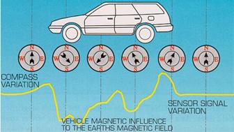
A Summary of Vehicle Detection and Surveillance Technologies use in Intelligent Transportation SystemsChapter 4 - In-roadway Sensor Technologies (cont)Magnetic SensorsPrinciples of OperationMagnetic sensors are passive devices that indicate the presence of a metallic object by detecting the perturbation (known as a magnetic anomaly) in the Earth's magnetic field created by the object. Figure 5 shows the magnetic anomaly produced by the magnetic dipoles, i.e., magnetic fields, on a steel vehicle when it enters the magnetometer's detection zone (Kell, 1990; Lenz, 1993; and Sampey, 1999). The upper part of the figure indicates how the vector addition of the dipole magnetic field and the Earth's quiescent magnetic field produces the magnetic anomaly. The lower portion of the figure depicts several dipoles on a vehicle and their effect on sensor output. Figure 6 illustrates the distortion induced in the Earth's magnetic field as a vehicle enters and passes through the detection zone of a magnetic sensor. Figure 6a depicts the magnetic field as the vehicle approaches the sensor. Figure 6b shows the field lines of flux as the vehicle begins to pass through the sensor's detection zone. Figure 6c illustrates the lines of flux when the entire vehicle is over the sensor. Application and UsesTwo types of magnetic sensors are used for traffic flow parameter measurement. The first type, two- and three-axis fluxgate magnetometers, detects changes in the vertical and horizontal components of the Earth's magnetic field produced by a ferrous metal vehicle. These sensors identify stopped and moving vehicles. The two-axis fluxgate magnetometer contains a primary winding and two secondary "sense" windings on a bobbin surrounding a high permeability soft magnetic material core. In response to the magnetic field anomaly, i.e., the magnetic signature of a vehicle, the magnetometer's electronics circuitry measures the output voltage generated by the secondary windings. The vehicle detection criterion is for the voltage to exceed a predetermined threshold. In the presence mode of operation, the detection output is maintained until the vehicle leaves the detection zone.
(a) Magnetic anomaly induced in the Earth's magnetic field by a magnetic dipole
(b) Perturbation of Earth's magnetic field by a ferrous metal vehicle. (Drawing courtesy of Nu-Metrics, Vanderbilt , PA ). Figure 5. Magnetic anomaly in the Earth's magnetic field induced by magnetic dipoles in a ferrous metal vehicle.
Figure 6. Distortion of Earth's magnetic field created as a vehicle enters and passes through the detection zone of a magnetic sensor. (Drawing courtesy of Nu-Metrics, Uniontown , PA ). An example of a wireless sensor that incorporates a two-axis fluxgate magnetometer is shown in Figure 7a. The G-8 series sensors fit into a 6-in diameter hole of 3¼-in depth (152.4-mm diameter X 82.6-mm depth). The sensor transmits data using the 2.45 GHz spread spectrum band to a base unit up to 300 ft (91 m) away. The base unit can be powered from batteries recharged by solar energy. The G-8 provides vehicle count, speed (up to 12 bins), length (up to 6 bins), lane occupancy, daily and annual average daily traffic (AADT), environmental monitoring of road surface temperature from -67oF to 185oF (-55oC to 85oC), road surface wet or dry condition, and chemical index. Polling intervals range from 5 to 120 minutes. The G-8 operates from 4 lithium thionyl chloride batteries for up to 5 years, typically 2 - 4 years depending on AADT and polling interval. Figure 7b illustrates a wireless three-axis magnetometer that measures the x-, y-, and z-components of the Earth's magnetic field. One or more of these sensors (across the width or length of the monitored road section) are required for applications as freeway and arterial count stations, stop bar detectors, and long loop emulators. They are installed by coring a 4-in. (10-cm) diameter hole approximately 2¼ in. (6.5 cm) deep, inserting the sensor into the hole so that it is properly aligned with the direction of traffic flow, and sealing the hole with fast drying epoxy. The sensor maintains two-way wireless communication with an access point device over a range of 75 to 150 ft (23 to 46 m). The communication range may be extended another 75 to 150 ft (23 to 46 m) by installing a repeater unit between the sensor and the nearest access point device. Sensor battery life depends on the vehicle detection application, but is expected to be 10 years. This sensor is available with two mounting options: flush mount and surface mount. Since fluxgate magnetometers are passive devices, they do not transmit an energy field and a portion of the vehicle must pass over the sensor for it to be detected. Consequently, a magnetometer can detect two vehicles separated by a distance of a foot. This potentially makes the magnetometer as accurate as or better than the inductive loop detector at counting vehicles. Conversely, the magnetometer is not a good locater of the perimeter of the vehicle. There is an uncertainty of about ±1.5 ft (45 cm). A single magnetometer is therefore seldom used for determining occupancy and speed in a traffic management application. Two closely spaced magnetometer sensors are preferred for that function.
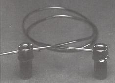
Figure 7. Two- and three-axis fluxgate magnetometer sensors. Previous magnetometer models were sensitive enough to detect bicycles passing across a 4-ft (1.2-m) span when the electronics unit was connected to two sensor probes buried at a depth of 6 in. (15 cm) and spaced 3 ft (0.9 m) apart. Fluxgate magnetometers can hold the presence of a vehicle for a considerable length of time and do not exhibit crosstalk interference. The second type of magnetic sensor is the magnetic detector, more properly referred to as an induction or search coil magnetometer. It normally detects only moving vehicles by measuring the change in the magnetic lines of flux caused by a moving ferrous metal vehicle. These devices contain a single coil winding around a permeable magnetic material rod core. Similar to the fluxgate magnetometer, magnetic detectors generate a voltage when a ferromagnetic object perturbs the Earth's magnetic field. However, most magnetic detectors cannot detect stopped or slow moving (i.e., vehicles with speeds less than approximately 5 mi/h) vehicles, since they require a vehicle to be moving or otherwise changing its signature characteristics with respect to time. Examples of sensors that use the induction magnetometer principle are shown in Figure 8.
Figure 8. Induction magnetometer sensors. AdvantagesTwo- and three-axis fluxgate magnetometers are less susceptible than loops to stresses of traffic. The pavement incursion for the sensor covers a smaller area and therefore may not affect pavement life as much as loops. Pavement cuts for data transmission to a controller are eliminated since the fluxgate magnetometers described above transmit data over wireless RF links. The induction or search coil magnetometer is also less susceptible than loops to stresses of traffic. The induction magnetometer can be used where loops are not feasible (e.g., bridge decks) and some models can be installed under the roadway without the need for pavement cuts. DisadvantagesInstallation of magnetic sensors requires pavement cut, coring, or boring under the roadway and thus requires lane closure during installation. Magnetic detectors cannot generally detect stopped vehicles. Also, some models have small detection zones. MANUFACTURER AND VENDOR INFORMATION Effective Date: 4/23/07 Manufacturer name: 3M Sales representative name(s): Intelligent Transportation Systems Mike Lemon Address: 3M Center, Bldg 225-4N-14 Address: 3M ITS St. Paul , MN 55144-1000 same Phone number: Phone number: (480) 221-5716 (cell) Fax number: Fax number: e-mail address: e-mail address: mjlemon@mmm.com URL address: www.mmm.com/ITS URL address: PRODUCT NAME/MODEL NUMBER: 3M 701 Traffic Sensor FIRMWARE VERSION/CHIP NO.: N/A SOFTWARE VERSION NO.: N/A GENERAL DESCRIPTION OF EQUIPMENT: 701 traffic sensors are used in single, double, or triple assemblies. In the latter two configurations, they are connected in series to extend lane coverage width. Each assembly is available with standard lead-in cable lengths. SENSOR TECHNOLOGY AND CONFIGURATION: The 701 traffic sensor is a transducer that converts changes in the vertical component of the earth's magnetic field to changes in inductance. Vehicles containing vertical components of ferromagnetic material distort the quiescent magnetic field of the earth, increasing the magnetic field at the sensor when vehicles move over the sensor. Changes in inductance can be sensed by a traffic monitoring card or Canoga C900 series vehicle detector suitably configured for the traffic sensor. The number of sensors required per lane is determined by lane width and types of vehicles to be detected. Up to four 701 traffic sensors can be connected in series. SENSOR INSTALLATION: The 701 traffic sensor is installed from the road surface. A 1-in. (2.5 cm) diameter hole is drilled for each 701 traffic sensor in the assembly. INSTALLATION TIME (Per Lane ): Not specified INSTALLATION REQUIREMENTS: For autos and trucks, a single sensor centered in a lane and buried 18-24 in. (41-61 cm) deep is typical. For small motorcycles and bikes, three sensors connected in series with 3-ft (91 cm) separation and buried 16-20 in. (40-50 cm) deep is typical. MAXIMUM NUMBER OF LANES MONITORED SIMULTANEOUSLY: N/A PRODUCT CAPABILITIES/FUNCTIONS: Replaces inductive loops for freeway applications, and counting and intersection applications. When connected to traffic monitoring cards, 701 traffic sensors provide accurate, real-time mean speed, count, and occupancy data and vehicle speed and length classification. They detect vehicles made of ferromagnetic materials in regions where the earth's vertical magnetic field is between 0.2 and 1.0 oersted. RECOMMENDED APPLICATIONS: All presence and passage applications POWER REQUIREMENTS (watts/amps): N/A POWER OPTIONS: N/A CLASSIFICATION ALGORITHMS: N/A TELEMETRY: N/A COMPUTER REQUIREMENTS: N/A DATA OUTPUT: N/A DATA OUTPUT FORMATS: N/A SUPPORTING DATA BASE MANAGEMENT SYSTEM: N/A EQUIPMENT AND INSTALLATION COSTS: Various STATES CURRENTLY USING THIS EQUIPMENT: Country/State Contact name Telephone number Please contact 3M for current list of references. MANUFACTURER AND VENDOR INFORMATION Effective Date: 4/23/07 Manufacturer name: 3M Sales representative name(s): Intelligent Transportation Systems Mike Lemon Address: 3M Center, Bldg 225-4N-14 Address: 3M ITS St. Paul , MN 55144-1000 same Phone number: Phone number: (480) 221-5716 (cell) Fax number: Fax number: e-mail address: e-mail address: mjlemon@mmm.com URL address: www.mmm.com/ITS URL address: PRODUCT NAME/MODEL NUMBER: 3M 702 Non-Invasive Traffic Sensor FIRMWARE VERSION/CHIP NO.: N/A SOFTWARE VERSION NO.: N/A GENERAL DESCRIPTION OF EQUIPMENT: 702 non-invasive traffic sensors are inserted into a 3-in. (7.6 cm) plastic conduit installed 18-24 in. (46-61 cm) below the road surface. Installing the sensors in a conduit leaves the road surface intact, bypasses the effects of poor pavement conditions and inclement weather, and virtually eliminates maintenance and service requirements. SENSOR TECHNOLOGY AND CONFIGURATION: The 702 non-invasive traffic sensor is a transducer that converts changes in the vertical component of the earth's magnetic field to changes in inductance. Vehicles containing vertical components of ferromagnetic material distort the quiescent magnetic field of the earth, increasing the magnetic field at the sensor when vehicles move over the sensor. Changes in inductance can be sensed by a traffic monitoring card or Canoga C900 series vehicle detector suitably configured for the traffic sensor. The number of sensors required per lane is determined by lane width and types of vehicles to be detected. For autos and trucks, a single sensor centered in a lane is typical. For small motorcycles and bikes, three sensors connected in series are typical. SENSOR INSTALLATION: 702 non-invasive traffic sensors are placed into special carriers and then inserted into 3-in. (7.6 cm) Schedule 80 conduit. Horizontal directional drilling techniques or open trenching is used for placement of the conduit. INSTALLATION TIME (Per Lane ): Sensors and carriers take less than an hour for insertion into the 3-in. (7.6 cm) Schedule 80 conduit. INSTALLATION REQUIREMENTS: Conduit is installed 21 ± 3 in. (53.3 ± 7.6 cm) below the road surface using horizontal directional drilling or open trenching techniques. Carriershold the 702 non-invasive traffic sensors in a fixed, vertical position as they are inserted into the installed, 3-in. (7.6 cm) conduit. The carriers' interlocking mechanism maintains the alignment of the sensors within ± 20o from vertical. MAXIMUM NUMBER OF LANES MONITORED SIMULTANEOUSLY: N/A PRODUCT CAPABILITIES/FUNCTIONS: Replaces inductive loops for freeway applications, and counting and intersection applications. When connected to traffic monitoring cards, 702 non-invasive traffic sensors provide accurate, real-time mean speed, count, and occupancy data and vehicle speed and length classification. They detect vehicles made of ferromagnetic materials in regions where the earth's vertical magnetic field is between 0.2 and 0.8 oersted. RECOMMENDED APPLICATIONS: All presence and passage applications POWER REQUIREMENTS (watts/amps): N/A POWER OPTIONS: N/A CLASSIFICATION ALGORITHMS: N/A TELEMETRY: N/A COMPUTER REQUIREMENTS: N/A DATA OUTPUT: N/A DATA OUTPUT FORMATS: N/A SUPPORTING DATA BASE MANAGEMENT SYSTEM: N/A EQUIPMENT AND INSTALLATION COSTS: Various STATES CURRENTLY USING THIS EQUIPMENT: Country/State Contact name Telephone number Please contact 3M for current list of references. MANUFACTURER AND VENDOR INFORMATION Effective Date: 6/18/07 Manufacturer name: Sensys Networks, Inc. Sales representative name(s): Address: 2560 Ninth Street, Suite 219 Address: Berkeley , CA USA 94710 Phone number: +1 (510) 548-4620 Phone number: Fax number: +1 (510) 548-8264 Fax number: e-mail address: info@sensysnetworks.com e-mail address: URL address: www.sensysnetworks.com URL address: PRODUCT NAME/MODEL NUMBER: Sensys™ Wireless Vehicle Detection System FIRMWARE VERSION/CHIP NO.: SOFTWARE VERSION NO.: GENERAL DESCRIPTION OF EQUIPMENT: The Sensys™ Wireless Vehicle Detection System uses pavement-mounted magnetic sensors (flush mount or surface mount) to detect the presence and movement of vehicles. The magneto-resistive sensors are wireless, transmitting their detection data in real-time via low-power radio technology to a nearby Sensys access point that relays the data to one or more local or remote traffic management controllers and systems. A single Sensys installation consists of a number of Sensys wireless sensors installed in or on the roadway at various locations as required by the particular vehicle detection application, a Sensys access point to receive the data from the sensors and process and relay it onward, and one or more Sensys repeaters as may be needed to support sensors installed beyond the radio range of the Sensys access point. SENSOR TECHNOLOGY AND CONFIGURATION: Each Sensys wireless sensor contains a magneto-resistive sensing device that measures the x-, y-, and z-axis components of the Earth's magnetic field at a 128 Hz sampling rate, combined with a low-power radio in a small, hardened plastic case for pavement mounting. SENSOR INSTALLATION: In typical traffic management applications, a Sensys wireless sensor is placed in the middle of a traffic lane where it will detect the presence and passage of vehicles. To measure vehicle speeds and length, two wireless sensors are installed in the same lane with the exact distance between them measured and configured in software upon installation. For stop bar detection applications where greater sensitivity is required and, for example, where a diagonal-slashed quadrupole (Type D) loop would be used just behind the stop bar, two Sensys wireless sensors should be installed parallel to the stop bar, each 1 ft (0.3 m) on one side or the other of the center of the traffic lane, and located 2 to 3 ft (0.6 to 0.9 m) from the stop bar where the center of the loop would have been placed. Sensor sensitivity is adjustable. INSTALLATION TIME (Per Lane ): Installation of each Sensys wireless sensor requires less than 10 minutes; two sensors are typically installed per lane for count station applications. INSTALLATION REQUIREMENTS: For a flush-mount sensor, installation requires boring a 4‑in. (10-cm) diameter hole approximately 2 ¼ in. (6.5 cm) deep at the desired sensing location, placing the sensor into the hole so that it is properly aligned with the direction of traffic, and sealing the hole with fast-drying epoxy. A hammer drill is recommended, but a core drill can alternatively be used. No lead-in cabling or long saw cuts are required, and the circular pavement hole produces the least amount of damage and stress to the roadway. Installation of a surface-mount Sensys wireless sensor is similar - orient and epoxy the sensor to its desired position in the roadway. A Sensys access point can be installed at any roadside location that provides adequate signal coverage to the nearby Sensys wireless sensors and repeaters as long as power for the access point device is available. Generally, a Sensys access point is pole-mounted at a height of 10 ft (3 m) or more, but it can also be mounted on a retaining wall, overpass, or other structure. A Sensys repeater is installed similarly, except that it does not require power. The maximum range between a Sensys access point or repeater and a Sensys wireless sensor is determined by site-specific variables as the local terrain, the mounting height of the access point/repeater, and whether the access point/repeater is pointed directly at the sensors. Ranges of 75 to 150 ft (3 to 46 m) are typical. MAXIMUM NUMBER OF LANES MONITORED SIMULTANEOUSLY: 1 (each Sensys wireless sensor acts independently, although many sensors can be supported by a single Sensys access point). PRODUCT CAPABILITIES/FUNCTIONS: Output data include vehicle counts, speed, occupancy, presence, headway, gap, direction of travel, and length classification. The system provides such capabilities as:
RECOMMENDED APPLICATIONS: Applications of the Sensys Wireless Vehicle Detection System are:
POWER REQUIREMENTS (watts/amps): Sensys wireless sensors and repeaters are battery-powered. Each Sensys access point uses an external DC power input, typically provided from a nearby power pedestal, traffic controller, or solar panel. Power consumption is 1.5 W to 3.5 W, depending on the access point options. POWER OPTIONS: Sensys access point options are available with either a 36-58 VDC isolated power input or, if solar power is used, a 9-20 VDC power input. CLASSIFICATION ALGORITHMS: TELEMETRY: Each Sensys installation can communicate its detection data in several ways:
COMPUTER REQUIREMENTS: Installation and configuration/control of the Sensys Wireless Vehicle Detection System is supported by Java software that runs on almost any PC operating system. DATA OUTPUT: Per-vehicle or averaged/binned data. DATA OUTPUT FORMATS: As required. SUPPORTING DATA BASE MANAGEMENT SYSTEM: Optional Sensys Networks Archive, Proxy, and Statistics (SNAPS) server can archive and provide statistical analysis of detection data. EQUIPMENT AND INSTALLATION COSTS (One-lane and four-lane): Pricing is competitive; please contact Sensys. STATES CURRENTLY USING THIS EQUIPMENT: Country/State Contact name Telephone number Arizona California Colorado Florida Iowa Kansas Maryland Michigan Minnesota Missouri Nevada Tennessee Texas Virginia Canada ( Winnipeg , Vancouver ) South Africa Australia Please contact Sensys for a complete list of references. PIEZOELECTRIC SENSORSPiezoelectric material converts kinetic energy to electrical energy. Polymers that exhibit this property to a high degree are ideal to use in the construction of piezoelectric sensors. Principles of OperationPiezoelectric materials generate a voltage when subjected to mechanical impact or vibration. Electrical charges of opposite polarity appear at the inner and outer faces of the material and induce a voltage. The measured voltage is proportional to the force or weight of the vehicle. The magnitude of the piezoelectric effect depends upon the direction of the force in relation to the axes of the crystal. Since the piezoelectric effect is dynamic, i.e., charge is generated only when the forces are changing, the initial charge will decay if the force remains constant (Castle Rock Consultants, 1988). Applications and UsesPiezoelectric sensors are utilized to classify vehicles by axle count and axle spacing and to measure vehicle weight and speed (the latter when multiple sensors are deployed). They are frequently used as part of weigh-in-motion systems. Class I piezoelectric sensors detect and weigh axles, while Class II sensors only detect the axle. There is typically a price advantage of buying Class II sensors for non-WIM applications, although the total installed cost of some Class I sensors is only fractionally more than that of a Class II sensor for sensors of the same length (Halvorsen, 1999). ConstructionOne coaxial piezoelectric tube sensor is constructed with a metal braided core element, which is surrounded by the piezoelectric material and a metal outer layer. During the manufacturing process, the sensor is subjected to an intense radial electric field, which polarizes piezoelectric material. The electrical field is applied as a corona to the cable before the outer metal jacket is attached. The field changes the amorphous polymer into a semi-crystalline form, while retaining many of the flexible properties of the original polymer (Halvorsen, 1999). Another type of piezoelectric sensor is Vibracoax cable, manufactured by Thermocoax. It utilizes a mineral-based powder as the piezoelectric material that forms the dielectric between the copper wire at the center of the coaxial cable and the solid copper tube that serves as the outer conductor. During manufacture, the temperature of the cable is increased to 400oC and a voltage is applied between the inner and outer conductors to polarize the powder by orienting the electrical charges on the molecules of powder. The voltage is maintained as the cable is cooled, thus stabilizing the polarized field. The cable can be supplied expoxied into an aluminum channel to ensure that it is installed without kinks as shown in Figure 9.
Figure 9. Vibracoax piezoelectric sensor mounted in aluminum channel as installed in a roadbed. (Drawing courtesy of IRD, Inc., Saskatoon , SK ). Vibracoax is recommended for weigh-in-motion, vehicle classification by axle count and spacing, gross vehicle and load measurement, speed measurement, and counting applications. Foam rubber is placed along the vertical sides of the sawcut when Vibracoax cable is utilized in weigh-in-motion systems manufactured by ECM, Inc. This technique enhances the vertical pressure measurement and reduces side stresses. This configuration is particularly useful for installations in concrete slabs that may contain cracks that would otherwise transfer horizontal forces to the cable sensor. The sawcut and cable are sealed with fillers that match the mechanical properties of the road surface to produce a slightly domed surface. Other examples of piezoelectric tube sensors include the Roadtrax BL and the BLC sensors. The Roadtrax piezoelectric sensor is manufactured with and without an aluminum channel for permanent or temporary installation in the roadbed (Roadtrax, 1995-1996). It supports Class I and Class II operations. The BL (Brass Linguini®) model is installed directly into the roadbed in a slot 0.75-in (19-mm) wide by 0.75-in (19-mm) deep (typical). Polyurethane, epoxy, and acrylic grouts are available for sealing the slot. When the BLC aluminum channel model is installed, as depicted in Figure 10, the same epoxy is used inside the channel to encapsulate the sensor and for installation in the road. This eliminates or greatly reduces temperature coefficient effects.
Figure 10. Roadtrax piezoelectric BLC sensor mounted in aluminum channel as installed in a roadbed (Roadtrax, 1995-1996). Bonding MaterialsA study by Fowler (Fowler, 1996) of current state practices for bonding piezoelectric sensors to pavement revealed that the bond between the piezoelectric sensor and the pavement was lost where rutting occurred. Several laboratory tests performed on the bonding material were found more relevant than others in predicting field performance of bonding agents. The most beneficial tests are listed in Table 3. Although all of these characteristics were critical, some were more indicative of desired material behavior as indicated by their rank. Recommended tests for determining bonding ability of agents used with piezoelectric sensors
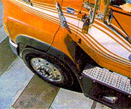
a3 = most important, 1 = least important. AdvantagesPiezoelectric sensors gather information when a tire passes over the sensor, thus creating an analogue signal that is proportional to the pressure exerted on the sensor. This property of piezoelectric sensors allows them to differentiate individual axles with high precision. In addition, on an installed cost basis, some types are only marginally more expensive than an inductive loop, but provide more information in the form of improved speed accuracy, the ability to determine the classification of the vehicle based on weight and axle spacing, and the capability to determine and monitor the weights of vehicles for WIM systems. DisadvantagesThe drawbacks to the use of piezoelectric tube or cable sensors are similar to those of inductive loop sensors in that they include disruption of traffic for installation and repair, failures associated with installations in poor road surfaces and wear, and use of substandard installation procedures. In many instances multiple detectors are required to instrument a location. In addition, resurfacing of roadways and utility repair can create the need to reinstall these types of sensors. Piezoelectric sensors have been known to be sensitive to pavement temperature and vehicle speed. MANUFACTURER AND VENDOR INFORMATION Effective Date: 29 March 2000 Manufacturer name: Sales representative name(s): Diamond Traffic. Guy Gibson Sr. , Vice President Address: Address: P.O. Box 1455 P.O. Box 1455 Oakridge , OR 97463 Oakridge , OR 97463 Phone number: (541) 782-3903 Phone number: Fax number: (541) 782-2053 Fax number: e-mail address: Diamondtrf@aol.com e-mail address: Diamondtrf@aol.com URL address: www.diamondtraffic.com URL address PRODUCT NAME/MODEL NUMBER: Phoenix Vehicle Classifier FIRMWARE VERSION/CHIP NO.: 2.39 SOFTWARE VERSION NO.: Trafman 469 GENERAL DESCRIPTION OF EQUIPMENT: Time interval vehicle classifier and counter utilizing loops, piezo, road tube, fiber optic, and radar SENSOR TECHNOLOGY AND CONFIGURATION: Loops, piezo, road tube, fiber optic, radar SENSOR INSTALLATION: INSTALLATION TIME (Per Lane ): Sensors cut into pavement can require 6-10 hours INSTALLATION REQUIREMENTS:. MAXIMUM NUMBER OF LANES MONITORED SIMULTANEOUSLY: 16 using loops for count or 8 using loops and piezo for classification PRODUCT CAPABILITIES/FUNCTIONS: Count, classify, vehicles, incident detection and notification. RECOMMENDED APPLICATIONS: 2 lane to multilane freeways for count and classification POWER REQUIREMENTS (watts/amps): Range form 50 milliamps to 100 milliamps POWER OPTIONS: 110 VAC, battery, or solar CLASSIFICATION ALGORITHMS: FHWA 13, European TELEMETRY: 300 to 19200. Optional 14.4K low power drew modem COMPUTER REQUIREMENTS: DATA OUTPUT: 28 print formats, spreadsheets DATA OUTPUT FORMATS: SUPPORTING DATA BASE MANAGEMENT SYSTEM: Mix of windows and DOS software, NT compatible EQUIPMENT AND INSTALLATION COSTS (One-lane and four-lane): One lane $1100 to $1500 Four lanes $1400 to $2000 STATES CURRENTLY USING THIS EQUIPMENT: Country/State Contact name Telephone number USA/Idaho Brian Hagen (208) 334-8250 USA/Nevada Cecil Crandel (775) 888-7155 USA/Washington John Rosen (360) 753-6100 USA/Colorado Steve Plasten (303) 757-9467 USA/Nebraska Terry Guy (402) 479-4509 USA/Connecticut Erick Glover (860) 594-2088 USA/Wyoming (307) 777-4433 MANUFACTURER AND VENDOR INFORMATION Effective Date: 2/29/00 Manufacturer name: Sales representative name(s): Truvelo Manufacturers (Pty) Ltd. James E. Kelly AVIAR Inc. Address: P.O. Box 14183 Address: P.O. Box 162184 Lyttelton 0140 Austin , TX 78716 South Africa Phone number: 011-27-11-314-1405 Phone number: (512) 295-5285 Fax number: 011-27-11-314-1409 Fax number: (512) 295-2603 e-mail address: rudi@truvelo.co.za e-mail address: aviar@aviarinc.com URL address: www.truvelo.co.za URL address: www.aviarinc.com PRODUCT NAME/MODEL NUMBER: The Combi Speed/Red Light Camera System FIRMWARE VERSION/CHIP NO.: N/A SOFTWARE VERSION NO.: N/A GENERAL DESCRIPTION OF EQUIPMENT: Automatic speed and/or traffic light violation recording system for portable and/or permanent installation in one compact unit. Evidence of violation is shown on photograph. SENSOR TECHNOLOGY AND CONFIGURATION: 3 or 4 piezo sensors for speed or 2 inductive loops/lane for presence at signalized intersection. SENSOR INSTALLATION: Either surface mounted or cut into roadway surface INSTALLATION TIME (Per Lane ): Portable installation: 60 min. for 3 lanes Permanent installation: 2 days INSTALLATION REQUIREMENTS: N/A MAXIMUM NUMBER OF LANES MONITORED SIMULTANEOUSLY: 3 lanes PRODUCT CAPABILITIES/FUNCTIONS: Monitor traffic for speed violations or red light violations. RECOMMENDED APPLICATIONS: Speed and red light enforcement POWER REQUIREMENTS (watts/amps): Portable: 12 volts D.C. Permanent: Either 12 volts D.C. or 220-240 volts single phase A.C. POWER OPTIONS: Either 12 volt battery or commercial source CLASSIFICATION ALGORITHMS: N/A TELEMETRY: N/A COMPUTER REQUIREMENTS: Internal microprocessors DATA OUTPUT: Photo evidence plus location code, time, date, speed, photo counter, traffic counter, statistical data (lowest/highest speed, average speed, 85 percentile speed, vehicle speed distribution) DATA OUTPUT FORMATS: On photo or on instrument display SUPPORTING DATA BASE MANAGEMENT SYSTEM: N/A EQUIPMENT AND INSTALLATION COSTS (One-lane and four-lane): Contact Truvelo for cost information. STATES CURRENTLY USING THIS EQUIPMENT: Country/State Contact name Telephone number USA/Florida Chief Tony Sparks (941) 534-5034 Bartow Police Dept. USA/Texas Walter Ragsdale (972) 238-4273 City of Richardson MANUFACTURER AND VENDOR INFORMATION Effective Date: February 2000 Manufacturer name: Sales representative name(s): Jamar Technologies James E. Martin Address: 151 Keith Valley Road Address: same Horsham , PA 19044 Phone number: (215) 491-4899 Phone number: same Fax number: (215) 491-4889 Fax number: e-mail address: sales@jamartech.com e-mail address: URL address: URL address: PRODUCT NAME/MODEL NUMBER: TRAXPRO FIRMWARE VERSION/CHIP NO.: TRAX Type III SOFTWARE VERSION NO.: TRAXPRO Version 1.1 GENERAL DESCRIPTION OF EQUIPMENT: Counter Classifier designed to record traffic in multiple lanes and save the data in a format that can be processed by the TRAXPRO program to give the user reports that include volumes, classification, speeds, gaps, and headways. SENSOR TECHNOLOGY AND CONFIGURATION: Piezo and loop technology in most of the standard configurations SENSOR INSTALLATION: Embedded in the road surface. Portable sensors due on the market in later 2000 INSTALLATION TIME (Per Lane ): For permanent sites approximately 2 hours per lane, depending on configuration INSTALLATION REQUIREMENTS: Good road surface with little or no rutting and no paving fractures MAXIMUM NUMBER OF LANES MONITORED SIMULTANEOUSLY: Eight PRODUCT CAPABILITIES/FUNCTIONS: Volume, speed, classifications, gaps and headways. RECOMMENDED APPLICATIONS: Any permanent or semi-permanent site POWER REQUIREMENTS (watts/amps): 15 mA battery powered, solar option available. A/C power optional. POWER OPTIONS: See above CLASSIFICATION ALGORITHMS: FHWA and custom ones per your needs TELEMETRY: Availability late 2000 COMPUTER REQUIREMENTS: Pentium DATA OUTPUT: ASCII & Binary DATA OUTPUT FORMATS: Standard SUPPORTING DATA BASE MANAGEMENT SYSTEM: Processed data files may be exported to Excel, Quattro-Pro, Lotus programs EQUIPMENT AND INSTALLATION COSTS (One-lane and four-lane): One-lane - approximately $4,000.00 and four-lane - approximately $6,000.00 STATES CURRENTLY USING THIS EQUIPMENT: Country/State Contact name Telephone number USA/Vermont Dave Gosselin (802) 828-2694 MANUFACTURER AND VENDOR INFORMATION Effective Date: March 22, 2000 Manufacturer name: International Road Sales representative name(s): Dynamics, Inc. Rod Klashinsky Address: 702 43rd Street East Address: Saskatoon SK , S7K 3T9 Canada Phone number: 306-653-6600 Phone number: Fax number: 306-242-5599 Fax number: e-mail address: info@irdinc.com e-mail address: URL address: www.irdinc.com URL address: PRODUCT NAME/MODEL NUMBER: IRD Truck Advisory Safety Systems FIRMWARE VERSION/CHIP NO.: N/A SOFTWARE VERSION NO.: N/A GENERAL DESCRIPTION OF EQUIPMENT: The IRD Truck Advisory Safety Systems determine truck speed, weight, height and classification (based on axle configuration). Using this information the systems are capable of displaying messages on a roadwide sign to instruct drivers to slow down prior to a sharp turn in the road or to proceed at a recommended speed prior to a steep decline in the road. SENSOR TECHNOLOGY AND CONFIGURATION: The system typically uses an inductive loop-Class I piezo sensor-Class I piezo sensor-loop configuration. SENSOR INSTALLATION: Sensors are saw-cut and grouted into the roadway. Sensor leads are run through conduit to a roadside cabinet. INSTALLATION TIME (Per Lane ): Depending on the application, installation of the in-road sensors, signs and associated electronics may take from 2 weeks to 1 month. INSTALLATION REQUIREMENTS: Please see attached product information for details. MAXIMUM NUMBER OF LANES MONITORED SIMULTANEOUSLY: Typically only a single lane of in-road equipment is required for the IRD Safety Systems. PRODUCT CAPABILITIES/FUNCTIONS: Truck Rollover Advisory, Downhill Truck Speed Advisory, and Runaway Truck Traffic signal control. RECOMMENDED APPLICATIONS: Truck Rollover Advisory, downhill Truck Speed Advisory, and runaway Truck Traffic Signal control. POWER REQUIREMENTS (watts/amps): 2.5 amps/35 watts (For the WIM electronics) POWER OPTIONS: 100-240 VAC, 50-60 Hz. (For the WIM electronics). CLASSIFICATION ALGORITHMS: Vehicles can be classified based on axle weights, axle spacings, axle groupings and GVW. TELEMETRY: Terminal software and standard telephone line with modem are required. COMPUTER REQUIREMENTS: Pentium II or better, 400 MHz min., 32 Mb RAM min., Expansion slots 1 ISA, 3 PCI, 1 ISA/PCI. DATA OUTPUT: Individual vehicle and vehicle summary data are stored on the WIM computer, which can be retrieved through a modem. Individual vehicle data can also be sent to an RS 232 port on the WIM in real-time. DATA OUTPUT FORMATS: The vehicle information is stored on disk files in a compressed format developed by IRD. Software is available to convert the data to CSV (Comma, Sparated Value) file. Several industry standard formats are available for the WIM vehicle data transmitted through the RS 232 port. SUPPORTING DATA BASE MANAGEMENT SYSTEM: Report generation software is available from IRD that reads the compressed vehicle data files directly. Raw data can also be exported to a file which can be read by any database system. EQUIPMENT AND INSTALLATION COSTS (One-lane and four-lane): 1-lane: $150,000 US and 4-lane: $300,000 US STATES CURRENTLY USING THIS EQUIPMENT: Country/State Contact name Telephone number USA/Pennsylvania (PennDot) Jim Garling (717) 787-3656 USA/Colorado (CDOT) Dave Judy (303) 512-5813 Weigh-in-Motion (WIM)Highway weigh-in-motion (WIM) systems are capable of estimating the gross vehicle weight of a vehicle and the portion of this weight carried by each wheel assembly (half-axle with one or more tires), axle, and axle group on the vehicle (ASTM E1318-02, 2002). WIM data are used by highway planners, designers, and enforcement agencies (e.g., Departments of Public Safety and state highway patrols). Application and UsesWIM systems increase the capacity of weigh stations and are often utilized when heavy truck traffic volumes cannot otherwise be accommodated. WIM systems provide highway planners and designers with time and date of traffic volume, speed, vehicle classification based on number and spacing of axles, and the equivalent single axle loading (ESAL) that heavy vehicles place on pavements and bridges. The heavy truck axle load data are used by motor vehicle enforcement officers to plan enforcement activities (McCall and Vodrazka, 1997). Software is frequently provided by the manufacturers to aid in system calibration and data analysis. The categories of WIM systems are listed in Table 4 along with the corresponding data each provide (ASTM E1318-02, 2002). Table 5 gives the functional performance requirements of WIM systems as defined by ASTM (ASTM E1318-02, 2002). Some states may impose more strict requirements such as those in Table 6 (McCall and Vodrazka, 1997). The accuracy of WIM systems is a function of four principal factors:
WIM System Categories, Applications, and Data Items
Vehicle dynamics are dependent on road surface roughness, type of vehicle suspension, vehicle dynamic balance, vehicle weight, vehicle speed, driver maneuvering, etc. Although most agencies attempt to install WIM systems in good pavement, unexpected deterioration or structural anomalies sometimes occur. For instance, WIM measurements worsen when asphalt pavements soften in hot weather and long concrete sections rock along a central axis when a heavy truck passes over the end of the section. The inherent variance of the WIM system is a function of the technology utilized in the system to measure axle weight. ASTM performance requirements for WIM systems
a Lower values are not usually a concern in enforcement. Source: Standard Specification for Highway Weigh-in-Motion (WIM) Systems with User Requirements and Test Method, Designation E 1318-02, 2005 Annual Book of ASTM Standards, Vol. 04.03, West Conshohocken, PA: ASTM. Table 6. California Department of Transportation (Caltrans) performance requirements for WIM systemsa
a Source: McCall, W. and W.C. Vodrazka Jr., States' Successful Practices Weigh-In-Motion Handbook, Center for Transportation Research and Education (CTRE), Iowa State University, Ames, IO, Dec. 15, 1997, http://www.ctre.iastate.edu/research/wim_pdf/index.htm. Table 7 gives typical values for the inherent variance component of the system accuracy (for a ±1 standard deviation confidence interval) for piezoelectric, bending plate, and single load cell systems. The table shows that it is common for WIM systems to be less accurate when weighing individual axle groups than when measuring gross vehicle weight. The effect of vehicle speed on total system accuracy is accounted for later in Table 8. Time out factors are sometimes programmed into WIM systems to assist in separating the weight of one vehicle from another. Inherent variance component of system accuracy a (1 standard deviation confidence interval)
a Source: Bergan, A.T., C.F. Berthelot, and B. Taylor, "Effect of Weigh in Motion Accuracy on Weight Enforcement Accuracy," Proc. of 7th Annual Meeting, ITS-America, Washington, D.C., 1997 and IRD Bending Plate and Load Cell Weigh-in-Motion Scales Technical Specifications, Aug. 1997 and Jan. 1998. b Gross vehicle weight c By comparison, the Kistler piezoelectric quartz sensor specification for wheel load measurement accuracy is approximately ±3 percent. Calibration ensures that the estimation of static weight by the WIM system closely approximates the true static weight. Calibration accounts for site-specific effects such as pavement temperature, vehicle speed, and pavement condition. Calibration procedures may include an acceptance testing phase and a recalibration phase. Acceptance testing of WIM systems as applied by Caltrans and reported in the State's Successful Practices Weigh-in-Motion Handbook (McCall and Vodrazka, 1997) has three stages: system component operation verification, initial calibration process, and a 72-h continuous operation verification. Table 8. Accuracy specifications for bending plate and load cell WIM scalesa (1 standard deviation confidence interval)
a From IRD Bending Plate and Load Cell Weigh-in Motion Scales Technical Specifications b Normally single load cell scales are calibrated for one of the speed ranges. If site conditions require more than one speed range, the system is calibrated for the range agreed to by the vendor and user.
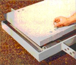
Recalibration occurs throughout the design life of the WIM site. Weight factors are adjusted or repairs made to the system when problems are identified during regularly scheduled data reviews. The four technologies used in WIM system weight measurement are bending plate, piezoelectric, load cell, and capacitance mat. Each is discussed in the following sections. Bending PlatePrinciples of Operation Bending plate WIM systems utilize plates with strain gauges bonded to the underside. As a vehicle passes over the bending plate, as illustrated in Figure 11, the system records the strain measured by the strain gauges and calculates the dynamic load. The static load is estimated using the measured dynamic load and calibration parameters. The calibration parameters account for factors such as vehicle speed, pavement condition, and suspension dynamics, which influence estimates of the static weight. The accuracy of bending plate WIM systems can be expressed as a function of the vehicle speed traversed over the plates, assuming the system is installed in a sound road structure and subject to normal traffic conditions. The accuracy specifications in Table 8 apply to bending plate scales manufactured by IRD. They are based on a minimum sample of 50 vehicles loaded to within 75% of the legal allowable limit. Vehicles that traverse the scale with more than a 10% speed variation, live loads, or liquid loads are not permitted in the sample.
Figure 11. Bending plate sensor. (Photographs courtesy of IRD, Inc., Saskatoon , SK ). Bending plate WIM systems contain either one or two scales and two inductive loop detectors (ILDs). A typical bending plate (or load cell) installation is shown in Figure 12. The scale is placed in the travel lane perpendicular to the direction of travel. When two scales are used in one lane, one scale is placed in each wheel path of the traffic lane so that the left and right wheels are weighed individually. The pair of scales is placed in the lane side-by-side or staggered by 5 m (16 ft). Bending plate systems with one scale in the right or left wheel path are usually used in low volume lanes. The inductive loops are placed upstream and downstream of the scales. The upstream loop detects vehicles and alerts the system to an approaching vehicle. The downstream loop determines vehicle speed based on the time it takes the vehicle to traverse the distance between the loops.
Figure 12. Bending plate or load cell WIM system (typical). Disadvantages Bending plate WIM systems are not as accurate as load cell systems and are considerably more expensive than piezoelectric systems. PiezoelectricPrinciples of Operation Piezoelectric WIM systems contain one or more piezoelectric sensors that detect a change in voltage caused by pressure exerted on the sensor by an axle and thereby measure the axle's weight. As a vehicle passes over the piezoelectric sensor, the system records the sensor output voltage and calculates the dynamic load. As with bending plate systems, the dynamic load provides an estimate of the static load when the WIM system is properly calibrated. The typical piezoelectric WIM system consists of at least one piezoelectric sensor and two ILDs. The piezoelectric sensor is placed in the travel lane perpendicular to the travel direction. The inductive loops are placed upstream and downstream of the piezoelectric sensor. The upstream loop detects vehicles and alerts the system to an approaching vehicle. The downstream loop provides data to determine vehicle speed and axle spacing based on the time it takes the vehicle to traverse the distance between the loops. Figure 13 shows a full lane-width piezoelectric WIM system installation. In this example, two piezoelectric sensors are utilized on either side of the downstream loop.
Figure 13. WIM installation with full-length piezoelectric sensors. A newer piezoelectric WIM sensor technology is the LINEAS quartz sensor manufactured by Kistler. It contains a quartz sensing element mounted along the centerline of an aluminum core as shown in Figure 14 (Kistler, 1997 and Caldera, 1996). The sensor is installed in a slot cut into the road surface and is grouted with a proprietary compound of epoxy and silica sand. The elastic and thermal properties of the compound closely match those of road surfaces. The sensor is isolated from side forces by an elastic material to help eliminate errors caused by a volume effect. The load bearing pad composed of a mixture of quartz sand and epoxy can be ground even with the road surface.
Figure 14. LINEAS quartz sensor (Drawing courtesy of Kistler Instruments AG Winterthur , Switzerland ). Advantages Piezoelectric tube or cable sensor WIM systems are among the least expensive systems in use today in terms of initial capital costs. The LINEAS quartz sensor is more expensive, but lasts longer, reducing life cycle maintenance costs and increasing reliability. Piezoelectric WIM systems can be used at higher speed ranges (10 to 70 mi/h) than other WIM systems. Piezoelectric WIM systems can be used to monitor up to four lanes. Quartz sensors do not generally age or fatigue. Temperature effects are negligible as the temperature coefficient of quartz is approximately -0.02 %/K. Since quartz crystals have no pyroelectric effect, rapid changes in temperature do not cause a drift in output signal. Wheel load measurements are to within ±3 percent irrespective of the vehicle speed and position of the wheel along the sensor. The accuracy of these sensors makes them performance and cost competitive with the load cell WIM systems discussed in the next section. Disadvantages Piezoelectric tube or cable sensor WIM systems (not quartz) are less accurate than load cell and bending plate WIM systems. These piezoelectric sensors may be sensitive to temperature and speed variations. Piezoelectric tube or cable sensors for WIM systems must be replaced at least once every 3 years. Load CellPrinciples of Operation A typical load cell WIM system includes a single load cell, at least one ILD, and one axle sensor. The load cell has two inline scales that operate independently. Off-scale sensors are integrated into the scale assembly to sense any vehicles that are not on the weighing surface. The single load cell system manufactured by IRD contains torsion bars within the WIM system frame that transmit all forces to the load cell. This load cell has a small amount of hydraulic fluid that causes a pressure transducer to relay weight information to roadside data analysis equipment. Load cells are durable and among the most accurate WIM systems as indicated in Table 7. The load cell is placed in the travel lane perpendicular to the direction of travel. The inductive loop is placed upstream of the load cell to detect vehicles and alert the system of an approaching vehicle. If a second inductive loop is used, it is placed downstream of the load cell to determine axle spacing and vehicle speed. The axle sensor can utilize piezoelectric technology or technology based on the change of sensor resistance with pressure. Advantages The load cell system is ranked among the most accurate WIM systems available. Therefore, the load cell WIM system can be utilized for traffic data collection as well as for weight enforcement purposes. Disadvantages The load cell is one of the most expensive WIM systems available today, in terms of initial capital costs and life cycle maintenance costs. Also, the load cell WIM system requires a complete replacement of the weighing mechanism after 5 years. Capacitance MatPrinciples of Operation A capacitance mat consists of a sandwich of metal steel sheets and dielectric material. In one configuration, displayed in Figure 15, a stainless steel sheet is surrounded by polyurethane dielectric material on either side. The outer surfaces of the polyurethane layers are enclosed by other stainless steel sheets. An a.c. voltage is applied across the sandwich of materials. When a vehicle passes over the mat, the spacing between the plates decreases and causes the capacitance to increase. This changes the resonant frequency of the electrical circuit of which the capacitance mat is a part. The resonant frequency, measured by the data analysis and recording equipment, is thus proportional to the axle weight. Capacitance mats are also manufactured utilizing aluminum plates separated by a grid of insulating material and air as the dielectric.
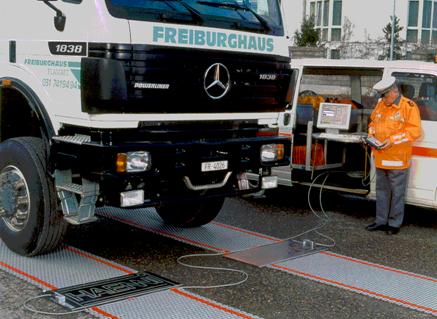
Figure 15. Capacitance mat sensor connected to data analysis equipment. (Photograph courtesy of LoadoMeter, Corp., Baltimore , MD ). Advantages Capacitance mat sensors can be used for portable as well as permanent WIM applications. These systems can monitor up to four lanes simultaneously. Disadvantages Capacitance mat WIM systems are not as accurate as the LINEAS quartz piezoelectric, load cell, and bending plate WIM systems for estimating weights. Also, the equipment and installation costs of these types of systems, whether portable or permanent, are similar to the load cell WIM system costs, which are among the most expensive WIM systems available. Weigh-in-Motion System CostsWIM system costs may be expressed in terms of the life cycle cost consisting of initial capital cost (in-road WIM equipment, installation labor and materials, initial calibration, and traffic control) and life-cycle maintenance costs (labor and materials, traffic control, and system recalibration). Table 9 contains budgetary initial capital costs for piezoelectric, bending plate, and load cell technologies assuming typical road, traffic, and weather conditions. These costs may vary from manufacturer to manufacturer and with sensor model. Roadside cabinets, WIM electronics, power and communication connections, etc. are not included as these are common to all the technologies. Budgetary initial capital costs of WIM systemsa
a Source: Bergan, A.T. , C.F. Berthelot , and B. Taylor , "Effect of Weigh in Motion Accuracy on Weight Enforcement Accuracy," Proceedings of 1997 Annual Meeting of ITS-America. The life-cycle maintenance costs vary due to differences in traffic volumes and truck weights, weather, original installation procedures, roadbed condition, onsite quality control, etc. Table 10 presents WIM system life-cycle maintenance and repair costs averaged over North American installations. The costs are based on performing annual routine maintenance (e.g., road inspection and crack filling) on the roadbed surrounding the WIM system. Piezoelectric sensors are assumed to require replacing every 3 years, bending plates refurbishing every 5 years, and single load cells replacing every 5 years. Life-cycle maintenance costs may vary with manufacturer and sensor model. Life-cycle maintenance costs of WIM systemsa
a Source: Bergan, A.T. , C.F. Berthelot , and B. Taylor , "Effect of Weigh in Motion Accuracy on Weight Enforcement Accuracy," Proceedings of 1997 Annual Meeting of ITS-America. The WIM system life-cycle costs may be amortized over the life cycle. Based on the initial installation and life-cycle maintenance costs shown in Tables 9 and 10 and a discount rate of 10 percent over a 20 year WIM system life cycle, the average annual cost for each WIM technology system is:
These figures show that the incremental cost for improved WIM system accuracy, durability, and reliability is relatively small when compared to the annual operating budget of a weight enforcement facility. Costs over other life-cycle intervals may be computed as required. MANUFACTURER AND VENDOR INFORMATION Effective Date: 4/10/07 Manufacturer name: Sales representative name(s): Truvelo Manufacturers (Pty) Ltd. James E. Kelly AVIAR Inc. Address: P.O. Box 14183 Address: P.O. Box 162184 Lyttelton 0140 Austin , TX 78716 South Africa Phone number: 011-27-11-314-1405 Phone number: (512) 295-5285 Fax number: 011-27-11-314-1409 Fax number: (512) 295-2603 e-mail address: rudi@truvelo.co.za e-mail address: jkelly24@peoplepc.com URL address: www.truvelo.co.za URL address: www.aviarinc.com PRODUCT NAME/MODEL NUMBER: Traffic Classifier/Data Logger (TCL-300) FIRMWARE VERSION/CHIP NO.: N/A SOFTWARE VERSION NO.: N/A GENERAL DESCRIPTION OF EQUIPMENT: TCL-300 stores and analyzes data (outputs 9 vehicle classes) using two inductive loops per lane on up to four lanes SENSOR TECHNOLOGY AND CONFIGURATION: 2 inductive loops/lane; up to 4 lanes monitored. SENSOR INSTALLATION: Temporary installation on surface of pavement or permanent installation in pavement surface INSTALLATION TIME (Per Lane ): Temp: 15 min Perm : 2 hr/lane INSTALLATION REQUIREMENTS: N/A MAXIMUM NUMBER OF LANES MONITORED SIMULTANEOUSLY: 4 lanes PRODUCT CAPABILITIES/FUNCTIONS: Vehicle number, date, time, direction, vehicle class using specially developed vehicle pattern recognition algorithms, vehicle length, headway, data for 20,000 individual vehicles can be stored in 256 kB of memory. Vehicle data are classified and placed into bins within the instrument according to a user-specified recording interval; 8,000 summarized data records can be stored in this mode. RECOMMENDED APPLICATIONS: Vehicle classification, vehicle following distances, queuing, and lane occupancy. POWER REQUIREMENTS (watts/amps): 6 volt internal battery (rechargeable from 12 volt battery, commercial power, or solar energy) POWER OPTIONS: See above CLASSIFICATION ALGORITHMS: Vehicle pattern recognition applied to light, medium, heavy or light, rigid trucks and buses, trucks and trailers, tractor and semi-trailer, multi-trailer heavy vehicles TELEMETRY: RS-232 serial port and modem COMPUTER REQUIREMENTS: Compatible PC DATA OUTPUT: See Product Capabilities DATA OUTPUT FORMATS: N/A SUPPORTING DATA BASE MANAGEMENT SYSTEM: N/A EQUIPMENT AND INSTALLATION COSTS (One-lane and four-lane): Temporary Permanent 1 lane 4 lane 1 lane 4 lane Equipment $4,000 $4,000 $4,700 $4,700 Installation costs $500 $1,500 $1,000 $2,500 STATES CURRENTLY USING THIS EQUIPMENT: Country/State Contact name Telephone number USA/Michigan Jim Kramer (517) 322-1736 MANUFACTURER AND VENDOR INFORMATION Effective Date: 4/10/07 Manufacturer name: Sales representative name(s): Truvelo Manufacturers (Pty) Ltd. James E. Kelly AVIAR Inc. Address: P.O. Box 14183 Address: P.O. Box 162184 Lyttelton 0140 Austin , TX 78716 South Africa Phone number: 011-27-11-314-1405 Phone number: (512) 295-5285 Fax number: 011-27-11-314-1409 Fax number: (512) 295-2603 e-mail address: rudi@truvelo.co.za e-mail address: jkelly24@peoplepc.com URL address: www.truvelo.co.za URL address: www.aviarinc.com PRODUCT NAME/MODEL NUMBER: Traffic Data Logger (TDL-500) FIRMWARE VERSION/CHIP NO.: N/A SOFTWARE VERSION NO.: N/A GENERAL DESCRIPTION OF EQUIPMENT: TDL-500 is used with inductive loops and capacitive weight sensors to provide high speed Weigh-In-Motion (WIM) data. SENSOR TECHNOLOGY AND CONFIGURATION: 2 inductive loops and 1 capacitive weight sensor per lane; up to 4 lanes monitored. SENSOR INSTALLATION: In the portable set-up, stick-on inductive loops and the Series 8 capacitive weight sensor are placed on top of the road pavement. This method allows for a cost-effective solution to monitor axle loading on all paved roads not covered by permanent sites. Typically data for one week are collected and processed. In this way many different sites can be monitored. TRUVELO also offers the Series 9 capacitive weight sensors placed in stainless steel pans, flush mounted with the pavement, to monitor axle loading on permanent sites. The Series 9 weight sensor can be replaced by a "Dummy" and moved to another site. INSTALLATION TIME (Per Lane ): Temp: 15 min Perm : 2 hr/lane INSTALLATION REQUIREMENTS: N/A MAXIMUM NUMBER OF LANES MONITORED SIMULTANEOUSLY: 4 lanes PRODUCT CAPABILITIES/FUNCTIONS: The road sensors consist of two inductive loops and one capacitive weight sensor per lane to cover a maximum of four traffic lanes. The TDL-500 combines the sensor information into a default data string consisting of vehicle number, arrival date and time, gap time, lane number, travel direction, vehicle straddling present, trailer present, vehicle chassis height, vehicle speed, vehicle length, vehicle class, number of axles, axle weight, axle distance, equivalent standard axle load, weight violations and bridge overloading. Data are stored into battery backed-up RAM of 512 kB to 8MB, space for 34000 to 650000 individual vehicle data strings. The operator can decide which data are to be stored, in what sequence and use logical AND/OR combinations of above parameters, e.g., all class 9 vehicles exceeding a certain speed AND a certain weight AND a certain length will be stored in individual data format, directly printed or sent to the computer. Certain operator selected data can be grouped per time interval into bins to maximize available memory space. The standard vehicle classification format is the American FHWA, but like all other parameters, is operator programmable. AND/OR combinations of number of axles, axle weight, axle distance, wheel base, gross vehicle mass, vehicle length, chassis height and trailer presence can be used to create virtually any classification scheme. RECOMMENDED APPLICATIONS: Vehicle classification. POWER REQUIREMENTS (watts/amps): 6 volt internal battery (rechargeable from 12 volt battery, commercial power, or solar energy) POWER OPTIONS: See above CLASSIFICATION ALGORITHMS: Vehicle pattern recognition used to provide outputs according to American FHWA classification scheme. TELEMETRY: RS232 serial port and modem COMPUTER REQUIREMENTS: Compatible PC DATA OUTPUT: See Product Capabilities DATA OUTPUT FORMATS: N/A SUPPORTING DATA BASE MANAGEMENT SYSTEM: N/A EQUIPMENT AND INSTALLATION COSTS (One-lane and four-lane): STATES CURRENTLY USING THIS EQUIPMENT: Country/State Contact name Telephone number MANUFACTURER AND VENDOR INFORMATION Effective Date: March 22, 2000 Manufacturer name: International Road Sales representative name(s): Dynamics, Inc. Rod Klashinsky Address: 702 43rd Street East Address: Saskatoon SK , S7K 3T9 Canada Phone number: 306-653-6600 Phone number: Fax number: 306-242-5599 Fax number: e-mail address: info@irdinc.com e-mail address: rod.klashinsky@ird.ca URL address: www.irdinc.com URL address: PRODUCT NAME/MODEL NUMBER: IRD 1068 Piezoelectric WIM System FIRMWARE VERSION/CHIP NO.: N/A SOFTWARE VERSION NO.: N/A GENERAL DESCRIPTION OF EQUIPMENT: The IRD 1068 Piezoelectric WIM system utilizes piezoelectric sensor technology to collect data on axle weights, vehicle classification (based on the number and spacing of axles) and vehicle speed. The system is accessible remotely using a standard telephone communication modem and PC for system monitoring, set-up and data collection. SENSOR TECHNOLOGY AND CONFIGURATION: The system uses an inductive loop-Class I piezo sensor-Class I piezo sensor-loop configuration to collect traffic data. SENSOR INSTALLATION: Please see attached product information for details. INSTALLATION TIME (Per Lane ): Approximately 1/2 day per lane. INSTALLATION REQUIREMENTS: Please see attached product information for details. MAXIMUM NUMBER OF LANES MONITORED SIMULTANEOUSLY: Eight PRODUCT CAPABILITIES/FUNCTIONS: Vehicle WIM data collection. RECOMMENDED APPLICATIONS: Vehicle WIM data collection. POWER REQUIREMENTS (watts/amps): 2.5 amps/35 watts POWER OPTIONS: 100-240 VAC, 50-60 Hz. CLASSIFICATION ALGORITHMS: Vehicles can be classified based on axle weights, axle spacings, axle groupings and GVW. TELEMETRY: Terminal software and standard COMPUTER REQUIREMENTS: Pentium II or better, 400 MHz min., 32 Mb RAM min., Expansion slots 1 ISA, 3PCI, 1 ISA/PCI. DATA OUTPUT: Individual vehicle and vehicle summary data are stored on the WIM computer, which can be retrieved through a modem. Individual vehicle data can also be sent to an RS 232 port on the WIM in real-time. DATA OUTPUT FORMATS: The vehicle information is stored on disk files in a compressed format developed by IRD. Software is available to convert the data to CSV (Comma, Separated Value) file. Several industry standard formats are available for the WIM vehicle data transmitted through the RS 232 port. SUPPORTING DATA BASE MANAGEMENT SYSTEM: Report generation software is available from IRD that reads the compressed vehicle data files directly. Raw data can also be exported to file, which can be read by any database system. EQUIPMENT AND INSTALLATION COSTS (One-lane and four-lane): 1-lane: $25,000 US 4-lane: $40,000 US STATES CURRENTLY USING THIS EQUIPMENT: Country/State Contact name Telephone number USA/California (CALTRANS) Rich Quinley (916) 645-5651 USA/New Jersey (NJ DOT) Lou Whiteley (609) 530-3501 USA/Indiana (IN DOT) Don Klepinger (317) 594-5264 MANUFACTURER AND VENDOR INFORMATION Effective Date: March 22, 2000 Manufacturer name: International Road Sales representative name(s): Dynamics, Inc. Rod Klashinsky Address: 702 43rd Street East Address: Saskatoon SK , S7K 3T9 Canada Phone number: 306-653-6600 Phone number: Fax number: 306-242-5599 Fax number: e-mail address: info@irdinc.com e-mail address: rod.klashinsky@ird.ca URL address: www.irdinc.com URL address: PRODUCT NAME/MODEL NUMBER: Model 1070 Portable WIM System FIRMWARE VERSION/CHIP NO.: N/A SOFTWARE VERSION NO.: WIM Data collection operation software MSDOS 6.22 operating system. GENERAL DESCRIPTION OF EQUIPMENT: Portable Weigh-in-Motion and data collection unit. SENSOR TECHNOLOGY AND CONFIGURATION: Uses Inductive Loops and Piezoelectric sensors. Most common configuration is Loop-Piezo-Piezo-Loop SENSOR INSTALLATION: Portable (On road) Permanent (in-road). INSTALLATION TIME (Per Lane ): Approximately 5-6 hours in a permanent Loop-Piezo-Loop configuration. Approximately 20-30 minutes in a portable application. INSTALLATION REQUIREMENTS: See attached installation sheet. MAXIMUM NUMBER OF LANES MONITORED SIMULTANEOUSLY: 4 lanes for weigh-in-motion and classifying. PRODUCT CAPABILITIES/FUNCTIONS: Collects and stores vehicle weight data including axle and gross vehicle weights. RECOMMENDED APPLICATIONS: Weight enforcement, Traffic planning, safety, and audit. POWER REQUIREMENTS (watts/amps): AC power for 12 volt, rechargeable battery. 24 hours operation with standard battery pack. POWER OPTIONS: Additional battery units, solar package. CLASSIFICATION ALGORITHMS: See attached. TELEMETRY: RS232 port with baud rates from 300 to 9,200. COMPUTER REQUIREMENTS: MSDOS lap top DATA OUTPUT FORMATS: Standard Data reporting package. SUPPORTING DATA BASE MANAGEMENT SYSTEM: Dependent on customer requirements. EQUIPMENT AND INSTALLATION COSTS (One-lane and four-lane): Permanent one lane - approx. US $15,000.00, 4 lanes approx. US $25,000.00. STATES CURRENTLY USING THIS EQUIPMENT: Country/State Contact name Telephone number USA/Nebraska USA/Colorado USA/North Carolina USA/West Virginia Canada/Saskatchewan Canada/Ontario Canada/New Brunswick Argentina Mexico Japan Korea India MANUFACTURER AND VENDOR INFORMATION Effective Date: March 22, 2000 Manufacturer name: International Road Sales representative name(s): Dynamics, Inc. Rod Klashinsky Address: 702 43rd Street East Address: Saskatoon SK , S7K 3T9 Canada Phone number: 306-653-6600 Phone number: Fax number: 306-242-5599 Fax number: e-mail address: info@irdinc.com e-mail address: rod.klashinsky@ird.ca URL address: www.irdinc.com URL address: PRODUCT NAME/MODEL NUMBER: Model 8000 Weigh-In-Motion Mat. FIRMWARE VERSION/CHIP NO.: N/A SOFTWARE VERSION NO.: MS-DOS 6.2 GENERAL DESCRIPTION OF EQUIPMENT: Portable AC/DC powered vehicle weighing and screening device. SENSOR TECHNOLOGY AND CONFIGURATION: Uses flat rectangular capacitance pads (2 per lane). SENSOR INSTALLATION: Portable, lay flat on road. INSTALLATION TIME (Per Lane ): Set-up time-less than 10 minutes. INSTALLATION REQUIREMENTS: Portable MAXIMUM NUMBER OF LANES MONITORED SIMULTANEOUSLY: One lane, slow speed (0-24 km). PRODUCT CAPABILITIES/FUNCTIONS: Weighs trucks to screen for overweight vehicles. RECOMMENDED APPLICATIONS: Prescreening for Weigh Stations, Random Spot Checks, Mobile Weigh. POWER REQUIREMENTS (watts/amps): AC Power or DC power (through automobile lighter) POWER OPTIONS: AC or DC CLASSIFICATION ALGORITHMS: See attached specifications TELEMETRY: N/A COMPUTER REQUIREMENTS: Laptop computer supplied with system DATA OUTPUT FORMATS: Vehicle information stored in data files and also sent to printer. SUPPORTING DATA BASE MANAGEMENT SYSTEM: Dependent upon customer requirements. EQUIPMENT AND INSTALLATION COSTS (One-lane and four-lane): Equipment costs US $18,500.00 for complete system. STATES CURRENTLY USING THIS EQUIPMENT: Country/State Contact name Telephone number USA/Wisconsin USA/North Dakota Brazil Uruguay Korea MANUFACTURER AND VENDOR INFORMATION Effective Date: March 22, 2000 Manufacturer name: International Road Sales representative name(s): Dynamics, Inc. Rod Klashinsky Address: 702 43rd Street East Address: Saskatoon SK , S7K 3T9 Canada Phone number: 306-653-6600 Phone number: Fax number: 306-242-5599 Fax number: e-mail address: info@irdinc.com e-mail address: rod.klashinsky@ird.ca URL address: www.irdinc.com URL address: PRODUCT NAME/MODEL NUMBER: IRD 1068 Single Load Cell Scale (SLC) WIM System FIRMWARE VERSION/CHIP NO.: N/A SOFTWARE VERSION NO.: N/A GENERAL DESCRIPTION OF EQUIPMENT: The IRD 1068 Single Load Cell (SLC) scale WIM system utilizes Single Load Cell (SLC) scale technology to collect data on axle weights, vehicle classification (based on the number and spacing of axles) and vehicle speed. The system is accessible remotely using a standard telephone communication modem and PC for system monitoring, set-up and data collection. SENSOR TECHNOLOGY AND CONFIGURATION: The system uses an inductive loop Single Load Cell scale - piezo sensor loop configuration to collect traffic data. SENSOR INSTALLATION: Please see attached product information for details INSTALLATION TIME (Per Lane ): Approximately 3 days per lane INSTALLATION REQUIREMENTS: Please see attached product information for details MAXIMUM NUMBER OF LANES MONITORED SIMULTANEOUSLY: 6 PRODUCT CAPABILITIES/FUNCTIONS: Vehicle WIM data collection RECOMMENDED APPLICATIONS: Vehicle WIM data collection POWER REQUIREMENTS (watts/amps): 2.5 amps/35 watts POWER OPTIONS: 100-240 VAC, 50-60 Hz CLASSIFICATION ALGORITHMS: Vehicles can be classified based on axle weights, axle spacings, axle groupings and GVW. TELEMETRY: Terminal software and standard telephone line with modem required. COMPUTER REQUIREMENTS: Pentium II or better, 400 MHZ min, 32 Mb RAM min, Expansion slots 1 ISA, 3PCI, 1 ISA/PCI. DATA OUTPUT: Individual vehicle and vehicle summary data are stored on the WIM computer which can be retrieved through a modem. Individual data can also be sent to an RS 232 port on the WIM in real time. DATA OUTPUT FORMATS: The vehicle information is stored on disk files in a compressed format developed by IRD. Software is available to convert the data to CSV (Comma, Separated Value) file. Several industry standard formats are available for the WIM vehicle data transmitted through the RS 232 port. SUPPORTING DATA BASE MANAGEMENT SYSTEM: Report generation software is available form IRD that reads the compressed vehicle data files directly. Raw data can also be exported to file, which can be read by any database system. EQUIPMENT COSTS (One-lane and four-lane): 1-lane: $75,000 US 4-lane: $215,000 US STATES CURRENTLY USING THIS EQUIPMENT: Country/State Contact name Telephone number USA/Indiana (INDOT) Don Klepinger (317) 591-5264 USA/Minnesota (MNDOT) Mark Novak (651) 296-2607 MANUFACTURER AND VENDOR INFORMATION Effective Date: 3/1/2000 Manufacturer name: Haenni/Mikros Sales representative name(s): Loadometer Corporation 3-G Nashua Court Address: Address: Baltimore , MD 21221-3133 Phone number: Phone number: (800) 753-6696 Fax number: Fax number: (410) 574-2856 e-mail address: e-mail address: gmuhler@loadometer.com URL address: URL address: www.loadometer.com PRODUCT NAME/MODEL NUMBER: WL110, Low Speed Portable WIM FIRMWARE VERSION/CHIP NO.: SOFTWARE VERSION NO.: GENERAL DESCRIPTION OF EQUIPMENT: System consists of 2 sensors, 4 leveling mats, connecting cables and hand held monitor. SENSOR TECHNOLOGY AND CONFIGURATION: Capacitance mat, stainless steel construction SENSOR INSTALLATION: None, above ground INSTALLATION TIME (Per Lane ): 5 minutes INSTALLATION REQUIREMENTS: None MAXIMUM NUMBER OF LANES MONITORED SIMULTANEOUSLY: One PRODUCT CAPABILITIES/FUNCTIONS: Capable of providing wheel loads, axle loads, axle group loads, gross vehicle weight and violations per set parameters RECOMMENDED APPLICATIONS: Statistical gathering purposes and as screening device in commercial vehicle weight law enforcement POWER REQUIREMENTS (watts/amps): Internal battery, external power supply POWER OPTIONS: Internal battery, external power supply. CLASSIFICATION ALGORITHMS: TELEMETRY: COMPUTER REQUIREMENTS: DATA OUTPUT: DATA OUTPUT FORMATS: SUPPORTING DATA BASE MANAGEMENT SYSTEM: EQUIPMENT AND INSTALLATION COSTS (One-lane and four-lane): Installation Costs: None, portable system Equipment Cost: $20,000 maximum STATES CURRENTLY USING THIS EQUIPMENT: Country/State Contact name Telephone number USA/Arizona Sgt. Charles Blundell (602) 773-3613 Lt. Ken Barton (602) 223-2522 USA/Exeter Township Officer Chris Neidert (617) 777-1490 USA/Falls Township Lt. Charles Shaffner (215) 949-9110 USA/Idaho DOT Alan Frew (208) 334-8694 USA / Kansas Hwy Patrol Sgt. David McKee (913) 296-7903 USA / Michigan St. Police Lt. Jim Charles (616) 784-8362 USA/Montana DOT Gary Marten (406) 444-6130 USA / Nebraska St. Patrol Lt. Jim Doggtt (402) 471-0105 USA/NH State Police Sgt. Wayne Peasley (603) 271-3339 USA/PA DOT Lance McAffe (717) 783-8776 USA/Uwchlan Township Cpl. Buddy Mauger (610) 524-1135 USA/Vermont DOT Ron Macie (802) 828-2067 USA/West VA DOT Jeff Davis (304) 558-3723 MANUFACTURER AND VENDOR INFORMATION Effective Date: March 22, 2000 Manufacturer name: International Road Sales representative name(s): Dynamics, Inc. Rod Klashinsky Address: 702 43rd Street East Address: Saskatoon SK , S7K 3T9 Canada Phone number: 306-653-6600 Phone number: Fax number: 306-242-5599 Fax number: e-mail address: info@irdinc.com e-mail address: rod.klashinsky@ird.ca URL address: www.irdinc.com URL address: PRODUCT NAME/MODEL NUMBER: IRD Dynamic Work-Zone Safety System FIRMWARE VERSION/CHIP NO.: N/A SOFTWARE VERSION NO.: N/A GENERAL DESCRIPTION OF EQUIPMENT: The IRD Work-Zone Safety System is a traffic control system for construction work zones. The system utilizes traffic detection sensors to detect traffic queue length and reduce the number of vehicles in the passing lane prior to work-zone approaches. SENSOR TECHNOLOGY AND CONFIGURATION: The IRD Dynamic work-Zone Safety System utilizes traffic sensors to detect vehicles and activate flashing lights mounted on "DO NOT PASS" panel signs prior to construction zones. Alternately, CMS or VMS signs can be used. SENSOR INSTALLATION: Sensors are mounted on roadside panel message signs. INSTALLATION TIME (Per Lane ): The system can typically be installed in 4-5 days. INSTALLATION REQUIREMENTS: Please see attached product information for details. MAXIMUM NUMBER OF LANES MONITORED SIMULTANEOUSLY: Only one lane is required to be monitored for this application. PRODUCT CAPABILITIES/FUNCTIONS: Detection of vehicles prior to a work-zone to trigger flashing lights mounted on roadway panel signs to instruct vehicles to merge into one lane. Since the signs are regulatory signs, offences are enforceable by law. RECOMMENDED APPLICATIONS: Detection of vehicles prior to a work-zone to trigger flashing lights mounted on roadway panel signs. POWER REQUIREMENTS (watts/amps): 12-24 AC or DC POWER OPTIONS: AC, DC, or solar. CLASSIFICATION ALGORITHMS: N/A TELEMETRY: N/A COMPUTER REQUIREMENTS: Laptop may be used to access information using serial communications software such as HyperTerminal. DATA OUTPUT: Serial or contact Closure. DATA OUTPUT FORMATS: ASCII SUPPORTING DATA BASE MANAGEMENT SYSTEM: N/A EQUIPMENT AND INSTALLATION COSTS (One-lane and four-lane): Approximately $60,000 US depending on the requirements (trailer and sign costs not included). STATES CURRENTLY USING THIS EQUIPMENT: Country/State Contact name Telephone number USA/Indiana (IN DOT) Dan Shamo (317) 232-5533
|
|||||||||||||||||||||||||||||||||||||||||||||||||||||||||||||||||||||||||||||||||||||||||||||||||||||||||||||||||||||||||||||||||||||||||||||||||||||||||||||||||||||||||||||||||||||||||||||||||||||||||||||||||||||||||||||||||||||||||||||||||||||||||||||||||||||||||||||||||||||||||||||||||||||||||||||||||||||||||||||||||||||||||