U.S. Department of Transportation
Federal Highway Administration
1200 New Jersey Avenue, SE
Washington, DC 20590
202-366-4000
A Summary of Vehicle Detection and Surveillance Technologies use in Intelligent Transportation SystemsChapter 5 - Over-roadway Sensor TechnologiesOver-roadway sensors are those that do not require the installation of the sensor directly onto, into, or below the road surface. Over-roadway sensors are mounted over the center of the roadway or to the side of the roadway. Video image processor, microwave radar, active and passive infrared, ultrasonic, and passive acoustic array are technologies applied to over-roadway sensors as discussed in the following sections. Video Image ProcessorVideo cameras were introduced to traffic management for roadway surveillance because of their ability to transmit closed circuit television imagery to a human operator for interpretation. Present-day traffic management applications use video image processing to automatically analyze the scene of interest and extract information for traffic surveillance and control. A video image processor (VIP) system (sometimes referred to as a machine vision processor) typically consists of one or more cameras, a microprocessor-based computer for digitizing and processing the imagery, and software for interpreting the images and converting them into traffic flow data. Principles of OperationVideo image processor systems detect vehicles by analyzing the imagery from a traffic scene to determine changes between successive frames. The image processing algorithms that analyze black and white imagery examine the variation of gray levels in groups of pixels contained in the video frames. The algorithms are designed to remove gray level variations in the image background caused by weather conditions, shadows, and daytime or nighttime artifacts and retain objects identified as automobiles, trucks, motorcycles, and bicycles. Traffic flow parameters are calculated by analyzing successive video frames. Color imagery can also be exploited to obtain traffic flow data. The improved resolution of color cameras and their ability to operate at low light levels is making this approach more viable. Three types of data extraction approaches are available to VIPs: tripline, closed-loop tracking, and data association tracking. Tripline systems allow the user to define a limited, but usually sufficient number of detection zones in the field of view of the video camera. When a vehicle crosses one of these zones, it is identified by noting changes in the pixels caused by the vehicle relative to the roadway in the absence of a vehicle. Surface-based and grid-based analyses are utilized to detect vehicles in tripline VIPs. The surface-based approach identifies edge features, while the grid based classifies squares on a fixed grid as containing moving vehicles, stopped vehicles, or no vehicles. Tripline systems estimate vehicle speed by measuring the time it takes an identified vehicle to travel a detection zone of known length. The speed is found as the length divided by the travel time ( Klein , 2001; Klein , et al., 2006). The advent of the VIP tracking approaches has been facilitated by low-cost, high throughput microprocessors. Closed-loop tracking systems are an extension of the tripline approach that permits vehicle detection along larger roadway sections. The closed-loop systems track vehicles continuously through the field of view of the camera. Multiple detections of the vehicle along a track are used to validate the detection. Once validated, the vehicle is counted and its speed is updated by the tracking algorithm (MacCarley, 1992). These tracking systems may provide additional traffic flow data such as lane-to-lane vehicle movements. Therefore, they have the potential to transmit information to roadside displays and radios to alert drivers to erratic behavior that can lead to an incident. Data association tracking systems identify and track a particular vehicle or groups of vehicles as they pass through the field of view of the camera. The computer identifies vehicles by searching for unique connected areas of pixels. These areas are then tracked from frame-to-frame to produce tracking data for the selected vehicle or vehicle groups. The markers that identify the objects are based on gradients and morphology. Gradient markers utilize edges, while morphological markers utilize combinations of features and sizes that are recognized as belonging to known vehicles or groups of vehicles (Wentworth, et. al., 1994). Systems are being developed that use data association tracking to gather travel time and origin-destination pair information by identifying and tracking vehicles as they pass from one camera's field of view to another's. Figures 16 and 17 show examples of video image processors that use the tripline approach. Some of these models also incorporate some vehicle tracking in their processing algorithms. 
(a) Autoscope VIPs (Photograph courtesy of Econolite Control Products, Anaheim , CA ) Figure 16. Tripline video image processors. (b) Traficon VIPs (Photograph courtesy of Traficon, Heule , Belgium ) (c) Iteris Vantage Edge2 processors (Photograph courtesy of Iteris, Anaheim , CA ) Figure 16. Video image processors (also referred to as machine vision processors).
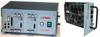
Peek VideoTrak Plus and UniTrak (Photograph courtesy of Quixote Traffic Corp.-Peek Traffic, Palmetto, FL) Figure 17. Video image processors (continued). Signal ProcessingImage formatting and data extraction are performed with firmware that allows image processing algorithms to run in real time. The hardware that digitizes the video imagery is commonly implemented on a single card in a personal computer architecture. Once the data are digitized and stored, spatial and temporal features are extracted from the vehicles in each detection area with a series of image processing algorithms. In the concept illustrated in Figure 18, a detection process establishes one or more thresholds that limit and segregate the data passed on to the rest of the algorithms. It is undesirable to severely limit the number of potential vehicles during detection, for once data are removed they cannot be recovered. Therefore, false vehicle detections are permitted at this stage since the declaration of actual vehicles is not made at the conclusion of the detection process. Rather, algorithms that are part of the classification, identification, and tracking processes still to come are relied on to eliminate false vehicles and retain the real ones ( Klein , 1997). Image segmentation is used to divide the image area into smaller regions (often composed of individual vehicles) where features can be better recognized. The feature extraction process examines the pixels in the regions for pre-identified characteristics, which are indicative of vehicles. When a sufficient number of these characteristics are present and recognized by the processing, a vehicle is declared present and its flow parameters are calculated. Artificial neural networks are another form of processing used to classify and identify vehicles, measure their traffic flow parameters, and detect incidents (Chang and Kunhuang, 1993). Features are not explicitly identified and sought when this processing approach is used. Rather software or hardware systems, which emulate the processing that occurs in the human brain, are trained to recognize vehicles. The digital imagery is presented to the trained network for vehicle classification and identification. VIPs with tracking capability use Kalman filter techniques to update vehicle position and velocity estimates. The time trace of the position estimates yields a vehicle trajectory, which can supply lane change and turning information. A signal processing approach implemented by Computer Recognition Systems incorporates wireframe models composed of line segments to represent vehicles in the image. This approach claims to provide more unique and discriminating features than other computationally viable techniques. Alternatively, artificial neural networks can be trained to recognize and count different classes of vehicles and detect incidents (Chang & Kunhuang, 1993). The neural network approach is incorporated by Nestor Traffic Systems, Inc. in their VIP products. An advantage of the Nestor implementation is that the camera can be repositioned for data acquisition and surveillance (Nestor Corp., 1999). VIPs that utilize tracking offer the ability to warn of impending incidents due to abrupt lane changes or weaving, calculate link travel times, and determine origin-destination pairs. The tracking concept is found in the Traffic Analysis System by Computer Recognition Systems, MEDIA4 by Citilog, and IDET-2000 by Sumitomo ( Klein , 2001).
Figure 18. Conceptual image processing for vehicle detection, classification, and tracking. ( Klein , 2006) A description of vehicle tracking methods suitable for VIPs is found in Kanhere, N.K. , et al., 2006. A summary of these tracking approaches appears below.
Application and UsesA VIP can replace several in-roadway inductive loops, provide detection of vehicles across several lanes, and perhaps lower maintenance costs. Some VIP systems process data from more than one camera and further expand the area over which data are collected. VIPs can classify vehicles by their length and report vehicle presence, flow rate, occupancy, and speed for each class. Other potentially available traffic parameters that can be obtained by analyzing data from a series of image processors installed along a section of roadway are density, link travel time, and origin-destination pairs. Mounting and Traffic Viewing ConsiderationsVIP cameras can be deployed to view upstream or downstream traffic. The primary advantage of upstream viewing is that incidents are not blocked by the resultant traffic queues as described in Table 11. However, tall vehicles such as trucks may block the line of sight and headlights may cause blooming of the imagery at night. With upstream viewing, headlight beams can be detected as vehicles in adjacent lanes on curved road sections. Downstream viewing conceals cameras mounted on overpasses so that driver behavior is not altered. Downstream viewing also makes vehicle identification easier at night through the information available in the taillights and enhances track initiation because vehicles are first detected when close to the camera. Although some manufacturers quote a maximum surveillance range for a VIP of ten times the camera mounting height, conservative design procedures limit the range to smaller distances because of factors such as road configuration (e.g., elevation changes, curvature, and overhead or underpass structures), congestion level, vehicle mix, and inclement weather. Other factors that affect camera installation include vertical and lateral viewing angles, number of lanes observed, stability with respect to wind and vibration, and image quality. VIP cameras can be mounted on the side of a roadway if the mounting height is high, that is 30 to 50 ft (9.1 to 15.2 m). For lower mounting heights of 20 ft (6.1 m), a centralized location over the middle of the roadway area of interest is required. However, the lower the camera mounting, the greater is the error in vehicle speed measurement, as the measurement error is proportional to the vehicle height divided by the camera mounting height. The number of lanes of imagery analyzed by the VIP becomes important when the required observation and analysis area is larger than the VIP's capability. For example, if the VIP provides data from detection zones in three lanes, but five must be observed, that particular VIP may not be appropriate for the application. VIPs that are sensitive to large camera motion may be adversely affected by high winds as the processor may assume that the wind-produced changes in background pixels correspond to vehicle motion. Image quality and interpretation can be affected by cameras that have automatic iris and automatic gain control. In tests conducted by California Polytechnic Institute at San Luis Obispo (Cal Poly SLO), these systems were disabled (Hockaday, 1991). In follow-up tests, Cal Poly SLO found VIPs better able to compensate for light level changes when the automatic iris was set to respond slowly to variations in light entering the camera. Video image processor characteristics in upstream and downstream viewing
AdvantagesVIP signal processing is continually improving its ability to recognize artifacts produced by shadows, illumination changes, reflections, inclement weather, and camera motion from wind or vehicle-induced vibration. However, artifacts persist and the user should evaluate VIP performance under the above conditions and other local conditions that may exist. In their 1998 report to the TRB Freeway Operations Committee, the New York State Department of Transportation (DOT) stated that one VIP model had difficulty detecting vehicles on a roadway lightly covered with snow in good visibility. Another model did not experience this problem. An example of the effect of day-to-night illumination change on VIP performance is illustrated in Figure 19. Shortly after 1900 hours, there are changes in the slopes of the vehicle count data produced by the VIPs due to either degradation in performance of the daytime algorithm or the different performance of the nighttime algorithm ( Klein , 1996). Figure 19. Vehicle count comparison from four VIPs and inductive loop detectors. Heavy congestion that degraded early VIPs does not appear to present a problem to more modern systems. Combined results for clear and inclement weather show vehicle flow rate, speed, and occupancy measurement accuracies in excess of 95 percent using a single detection zone and a camera mounted at a sufficiently high height (Michalopoulos, et. al., 1993). VIPs with single or multiple detection zones per lane can be used to monitor traffic on a freeway. For signalized intersection control, where vehicle detection accuracies of 100 percent are desired, the number of detection zones per lane is increased to between two and four, dependent on the camera mounting and road geometry. Even with multiple detection zones, cameras used in a side-viewing configuration that are not mounted high enough, on the order of 30 ft (9 m) rather than 50 ft (15 m)] or are not directly adjacent to the roadway can degrade the vehicle detection accuracy to 85 percent or less (Klein, 1999, vols. 1 and 2). The study that produced these results also reported that vehicle detection was sometimes sensitive to the vehicle-to-road color contrast. Test results from other VIP performance assessments include (Kranig J., et al., 1997 and Middleton, D. and R. Parker, 2002):
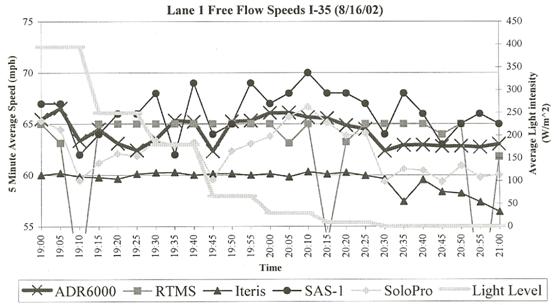
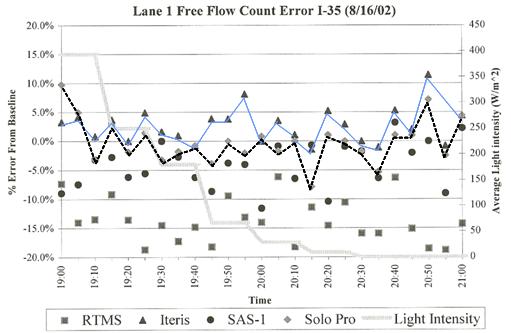
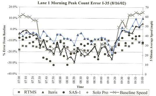
Figures 20 through 22 show VIP test results based on 5-minute averaged data from the Middleton and Parker 2002 evaluation of over-roadway sensors. Figure 20 illustrates vehicle speed as a function of ambient lighting conditions. There is some underreporting of speed by the VIPs with respect to the baseline values, but the speed measurement appears not to be sensitive to the light intensity. Figure 21 depicts the percent error in vehicle count, with respect to the baseline value, versus ambient lighting. Again there appears not to be a large effect on count as reported by the VIPs with respect to lighting changes, although there is a tendency to go from undercounting to overcounting as light intensity decreases. Figure 22 displays the percent error in vehicle count, with respect to the baseline value, as a function of vehicle speed. Peak morning traffic flows are seen to produce undercounting of 10 to 25 percent by the VIPs with respect to the baseline values.
Figure 20. Vehicle speed vs. lighting VIP test results.
Figure 21. Vehicle count vs. lighting VIP test results.
Figure 22. Vehicle count vs. speed VIP test results. DisadvantagesSome disadvantages of the video image processor include its vulnerability to viewing obstructions; inclement weather; shadows; vehicle projection into adjacent lanes; occlusion; day-to-night transition; vehicle/road contrast; water; salt grime; icicles; and cobwebs on camera lens that can affect performance. Also, some models are susceptible to camera motion caused by strong winds. Furthermore, the installation of a video image processor may require 50 ft or greater camera mounting height (in a side mounting configuration) for optimum presence detection and speed measurement. A video image processor arrangement is generally cost effective only if many detection zones are required within the field of view of the camera. MANUFACTURER AND VENDOR INFORMATION Effective Date: 5/10/07 Manufacturer name: Econolite Sales representative name(s): Control Products, Inc. Scott Robinson Address: 3360 E. La Palma Avenue Address: 3360 E. La Palma Avenue Anaheim , California 92806-2856 Anaheim , California 92806-2856 Phone number: (714) 630-3700 Phone number: (714) 630-3700 Fax number: (714) 630-6349 Fax number: (714) 666-8354 e-mail address: socalsales@econolite.com e-mail address: srobinson@econolite.com URL address: http://www.econolite.com/products/ URL address: PRODUCT NAME/MODEL NUMBER: Autoscope Solo Terra Video Detection System FIRMWARE VERSION/CHIP NO.: Updates provided as required by the manufacturer. SOFTWARE VERSION NO.: Updates provided as required by the manufacturer. GENERAL DESCRIPTION OF EQUIPMENT: The Autoscope Solo Terra sensor contains a color video camera as part of this integrated detection and surveillance machine vision system. It installs with three wires and reduces maintenance with ClearVision faceplate coating. The Solo Terra sensor provides timely vehicle detection, traffic data measurement, speed, and incident detection data. SENSOR TECHNOLOGY AND CONFIGURATION: Machine vision - video image processing, pixel tracking, and tripline technology. SENSOR INSTALLATION: Autoscope Solo Terra unit installs on existing signal poles, mast arms, and luminaire standards. INSTALLATION TIME (Per Lane ): One hour typical per camera including camera installation, wiring, and detector layout, but not including pulling wires through conduit. Moving the bucket truck into proper position consumes the majority of the installation time. INSTALLATION REQUIREMENTS: Camera and sensor are integrated into one unit. Camera mounting over center of monitored lanes provides optimum performance. Minimum camera mounting height is 30 ft. Greater heights may be required to minimize vehicle occlusion when using side-mounted cameras. MAXIMUM NUMBER OF LANES MONITORED SIMULTANEOUSLY: Six to seven PRODUCT CAPABILITIES/FUNCTIONS:
RECOMMENDED APPLICATIONS: Intersection detection, freeway/tollways mgt. Construction zone monitoring, railway crossings, bridges, tunnels, security areas. POWER REQUIREMENTS (watts/amps): 15 W, 110/220 VAC, 50/60 Hz POWER OPTIONS: None CLASSIFICATION ALGORITHMS: User selectable by length into 5 - 6 bins. TELEMETRY: Broadband communications up to 5MB/sec with RJ-45 connection on Terra Interface Panel (TIP). COMPUTER REQUIREMENTS: Uses image processor hardware built into Autoscope system. DATA OUTPUT: ASCI text format or compatible with multiple standard spreadsheet programs. Video available in NTSC and PAL formats. DATA OUTPUT FORMATS: Per above in time slices from 10-60 seconds and 5-60 minutes. SUPPORTING DATA BASE MANAGEMENT SYSTEM: Model dependent. EQUIPMENT AND INSTALLATION COSTS (One-lane and four-lane): 1 lane: $5,000 4 lane: WARRANTY: Two years standard, option to extend to five years available. STATES CURRENTLY USING THIS EQUIPMENT: Country/State Contact name Telephone number Please contact Econolite for current list of references. MANUFACTURER AND VENDOR INFORMATION Effective Date: 5/10/07 Manufacturer name: Econolite Sales representative name(s): Control Products, Inc. Scott Robinson Address: 3360 E. La Palma Avenue Address: 3360 E. La Palma Avenue Anaheim , California 92806-2856 Anaheim , California 92806-2856 Phone number: (714) 630-3700 Phone number: (714) 630-3700 Fax number: (714) 630-6349 Fax number: (714) 666-8354 e-mail address: socalsales@econolite.com e-mail address: srobinson@econolite.com URL address: http://www.econolite.com/products/ URL address: PRODUCT NAME/MODEL NUMBER: Autoscope Solo Pro II FIRMWARE VERSION/CHIP NO.: Updates provided as required by the manufacturer. SOFTWARE VERSION NO.: Updates provided as required by the manufacturer. GENERAL DESCRIPTION OF EQUIPMENT: The Autoscope Solo Pro II sensor contains an integrated color camera, zoom lens, and machine vision processor in one housing. Twisted-pair wiring to the Solo Pro II sensor eliminates need for coaxial cables. Remote connections are made with a phone line or wireless radio to bring compressed video and data back to a traffic management center. SENSOR TECHNOLOGY AND CONFIGURATION: Machine vision - video image processing, pixel tracking, and tripline technology. SENSOR INSTALLATION: Autoscope Solo Pro II unit installs on existing traffic signal poles, mast arms, and luminaire standards. INSTALLATION TIME (Per Lane ): One hour typical per camera including camera installation, wiring, and detector layout, but not including pulling wires through conduit. INSTALLATION REQUIREMENTS: Camera mounting over center of monitored lanes provides optimum performance. Minimum camera mounting height is 30 ft. Greater heights may be required to minimize vehicle occlusion when using side-mounted cameras. MAXIMUM NUMBER OF LANES MONITORED SIMULTANEOUSLY: Six to seven PRODUCT CAPABILITIES/FUNCTIONS:
RECOMMENDED APPLICATIONS: Freeway, intersection, bridge, tunnel, railroad, traffic-monitoring, and incident prevention applications. The Autoscope Communications Server Software Developer's Kit (SDK) allows a programmer to create new client applications for display, incident alarms, and traffic parameter databases. POWER REQUIREMENTS (watts/amps): 15 W: 24 VAC, 50/60 Hz or 10 to 28 VDC. POWER OPTIONS: See above CLASSIFICATION ALGORITHMS: User selectable by length into 5 - 6 bins. TELEMETRY: RS-485 interface with supervisor computer and detectors. COMPUTER REQUIREMENTS: Uses image processor hardware built into Autoscope system. DATA OUTPUT: ASCI text format or compatible with multiple standard spreadsheet programs. Video available in NTSC and PAL formats. DATA OUTPUT FORMATS: Per above in time slices from 10-60 seconds and 5-60 minutes. SUPPORTING DATA BASE MANAGEMENT SYSTEM: Model dependent. EQUIPMENT AND INSTALLATION COSTS (One-lane and four-lane): 1 lane: $5,000 4 lane: 14 approach intersection, $18,200 WARRANTY: Two years standard, option to extend to five years available. STATES CURRENTLY USING THIS EQUIPMENT: Country/State Contact name Telephone number Please contact Econolite for current list of references. MANUFACTURER AND VENDOR INFORMATION Effective Date: 7/10/07 Manufacturer name: Iteris, Inc. Sales representative name(s): Michael Post Address: 1700 Carnegie Avenue Address: same Santa Ana , CA 92705 Phone number: (888) 254-5487 Phone number: same Fax number: (714) 780-7246 Fax number: same e-mail address: vantage@iteris.com e-mail address: mjp@iteris.com URL address: www.iteris.com URL address: PRODUCT NAME/MODEL NUMBER: Vantage Edge2 Video Detection System FIRMWARE VERSION/CHIP NO.: 1.12 (as of 5/2007) SOFTWARE VERSION NO.: Not applicable GENERAL DESCRIPTION OF EQUIPMENT: Iteris' Vantage Edge2™ is a machine vision processor consisting of a family of modules that provide 170/2070, TS-1, or TS-2 detection outputs to an intersection traffic controller for actuated operation. The modular approach allows the configuration to grow and adapt as the size and complexity of the intersection change. It is programmed using built-in menus that appear as a graphics overlay on the video image. Programming a virtual detection zone takes less than a minute, reducing installation time for both permanent and temporary installations. The image processing algorithms provide vehicle detection during most weather and lighting conditions. In addition, the Vantage Edge2™ provides failsafe operation mechanisms and motion stabilization in high wind conditions. Detection zones can be modified rapidly as needed. SENSOR TECHNOLOGY AND CONFIGURATION: Machine vision - video image processing, pixel tracking, and trip-line technology. Cameras are analog color or monochrome CCD units - available in wired or wireless configurations. SENSOR INSTALLATION: Camera installs on existing signal poles, mast arms, and luminaire standards. INSTALLATION TIME (Per Lane ): 15 - 30 minute average INSTALLATION REQUIREMENTS: Camera mounting over center of monitored lanes is ideal, with minimum height of 30 ft. Greater heights may be required to minimize vehicle occlusion when using side-mounted cameras. MAXIMUM NUMBER OF LANES MONITORED SIMULTANEOUSLY: 6 lanes PRODUCT CAPABILITIES/FUNCTIONS:
RECOMMENDED APPLICATIONS: Intersection signal control, ramp metering, highway monitoring and incident detection. POWER REQUIREMENTS (watts/amps): 115 and 240 VAC 60/50 Hz, 137 watts max. POWER OPTIONS: See above CLASSIFICATION ALGORITHMS: TELEMETRY: Via RS 232 serial port or RJ45 Ethernet using eAccess communication module, which is an 802.3 compliant TCP/IP interface. The eAccess communications module contains a hardened modem that supports remote access from a PSTN line. Access to Vantage video detection processors can also be made via cable modem, DSL modem, or local area networks. Vantage eAccess Ethernet port enables MPEG-2 streaming video to be viewed on a personal computer using Internet browsers. Remote configuration and diagnostics can also be retrieved using the browser-based remote access firmware embedded within Vantage eAccess. In addition to eAccess, a wireless system utilizes the license-free 2.4 GHz band to transmit live video from the video detection CCTV camera to the controller cabinet. COMPUTER REQUIREMENTS: None for setup or operation DATA OUTPUT: Presence, Delay, Extend, Count, CSO (Count, Speed, and Occupancy), Pulse, Demand and Passage. DATA OUTPUT FORMATS: Up to 4 BNC video inputs per Edge2 module, NTSC or PAL 1 BNC video output per Edge2 module USD female for pointing device per Edge2 or eAccess module DB9 male for RS-232 interface per Edge2 module DB15 female for TS-2 outputs when using TS2-IM module DB37 female for TS-1 outputs when using IOM module SUPPORTING DATA BASE MANAGEMENT SYSTEM: VRAS - Vantage Remote Access Software for remote access EQUIPMENT AND INSTALLATION COSTS (One-lane and four-lane): Approximately $5,000.00 per approach STATES CURRENTLY USING THIS EQUIPMENT: Country/State Contact name Telephone number Please contact Iteris for current list of references. MANUFACTURER AND VENDOR INFORMATION Effective Date: 5/10/07 Manufacturer name: Traficon Sales representative name(s): Traficon USA LLC Address: Meensesteenweg 449/2 Address: 14520 Avion Parkway B-8501 Bissegem , Belgium Suite 305 Chantilly , Virginia 20151 Phone number: 32-56 37 22 00 Phone number: (703) 961 9617 Fax number: 32-56 37 21 96 Fax number: (703) 961 9606 e-mail address: traficon@traficon.com e-mail address: traficon@traficonusa.com URL address: www.traficon.com URL address: www.traficon.com/contact/ usa_ general.jsp PRODUCT NAME/MODEL NUMBER: VIP 3D.x Video Image Processor FIRMWARE VERSION/CHIP NO.: SOFTWARE VERSION NO.: GENERAL DESCRIPTION OF EQUIPMENT: The VIP3D.x Video Image Processor provides traffic data and information concerning the presence of vehicles approaching or waiting at the intersection. The input is composite video 751Vtt CCIR/EIA. The VIP3D.x comes in two versions:
In a typical installation, two VIP3D.2 units are combined with one VIEWCOM/E for remote monitoring and change of configurations. The VIP 3D.x is a direct plug-in module for Type 170, NEMA TS-1 and TS-2 controller cabinets. SENSOR TECHNOLOGY AND CONFIGURATION: Machine vision - video image processing, pixel tracking, and tripline technology. SENSOR INSTALLATION: Camera installs on existing signal poles, mast arms, and luminaire standards. Machine vision processor installs in controller cabinet. INSTALLATION TIME (Per Lane ): One hour INSTALLATION REQUIREMENTS: Bucket truck to mount camera. Camera mounting over center of monitored lanes provides optimum performance. Minimum camera mounting height is 30 ft. Greater heights may be required to minimize vehicle occlusion when using side-mounted cameras. MAXIMUM NUMBER OF LANES MONITORED SIMULTANEOUSLY: Eight PRODUCT CAPABILITIES/FUNCTIONS:
RECOMMENDED APPLICATIONS: Intersection vehicle detection for traffic signal control. Types of information available are vehicle presence; traffic data such as counts, speeds, classification, occupancy, density, headway, gap time; alarm events; wrong way driver detection; queue length; turning movement count. POWER REQUIREMENTS (watts/amps): 10.8v to 26.5v DC VIP3D.2 draws 200mA at 24v VIP3D.1 draws 160mA at 24v 4 I/O draw 30mA at 24v POWER OPTIONS: See above. CLASSIFICATION ALGORITHMS: Available TELEMETRY: System connection via VIEWCOM/E (Ethernet). VIP3.x Link Software via serial communication RS232. Real time video output on module. COMPUTER REQUIREMENTS: Not mandatory DATA OUTPUT: The VIP3D.2 provides 24 digital outputs in total using expansion output modules (available in 3 types: 2 I/O, 4 I/O or 12 I/O). Presence, volume, speed data are provided. DATA OUTPUT FORMATS: Analog video output with overlay of system information data and detection lines, auto diagnostic LED indicators, VIP3D.2 main board contains four optically isolated open-collector outputs, expansion modules 2 I/O, 4 I/O and 12 I/O: 2, 4 or 12 digital in/outputs (with dip switches for selection of inputs and outputs) SUPPORTING DATA BASE MANAGEMENT SYSTEM: Watts Traffic Management Software (PC-based). EQUIPMENT AND INSTALLATION COSTS (One-lane and four-lane): Approximately $5,000 per approach STATES CURRENTLY USING THIS EQUIPMENT: Country/State Contact name Telephone number USA/Lynnwood, Washington USA/Tacoma, Washington Colorado Springs , CO Baltimore , MD MANUFACTURER AND VENDOR INFORMATION Effective Date: 5/10/07 Manufacturer name: Traficon Sales representative name(s): Traficon USA LLC Address: Meensesteenweg 449/2 Address: 14520 Avion Parkway B-8501 Bissegem , Belgium Suite 305 Chantilly , Virginia 20151 Phone number: 32-56 37 22 00 Phone number: (703) 961 9617 Fax number: 32-56 37 21 96 Fax number: (703) 961 9606 e-mail address: traficon@traficon.com e-mail address: traficon@traficonusa.com URL address: www.traficon.com URL address: www.traficon.com/contact/ usa_ general.jsp PRODUCT NAME/MODEL NUMBER: TRAFICAM® Integrated Camera and Presence Sensor for intersection applications - 2nd Generation FIRMWARE VERSION/CHIP NO.: SOFTWARE VERSION NO.: GENERAL DESCRIPTION OF EQUIPMENT: TrafiCam® integrates both a CMOS camera and detector in one compact box. This sensor monitors the presence of vehicles approaching or waiting at an intersection. SENSOR TECHNOLOGY AND CONFIGURATION: Machine vision - video image processing, pixel tracking, and tripline technology. SENSOR INSTALLATION: Camera and machine vision processor install on existing signal poles, mast arms, and luminaire standards. Wide field of view and narrow field of view lenses are available, depending on close or long range viewing, respectively. INSTALLATION TIME (Per Lane ): One hour INSTALLATION REQUIREMENTS: Bucket truck to mount sensor. Camera mounting over center of monitored lanes provides optimum performance. Minimum camera mounting height is 30 ft. Greater heights may be required to minimize vehicle occlusion when using side-mounted cameras. MAXIMUM NUMBER OF LANES MONITORED SIMULTANEOUSLY: Eight PRODUCT CAPABILITIES/FUNCTIONS:
RECOMMENDED APPLICATIONS: Intersection vehicle detection for traffic signal control. Types of information available are vehicle presence; traffic data such as counts, speeds, classification, occupancy, density, headway, gap time; alarm events; wrong way driver detection; queue length; turning movement count. POWER REQUIREMENTS (watts/amps): 12-26 VAC/DC, ≤78mA @ 12VDC, ≤42mA @ 24VDC POWER OPTIONS: See above. CLASSIFICATION ALGORITHMS: Available TELEMETRY: Sensor configuration performed via USB connection. With a portable PC or PDA, sensor set-up is available in your native language through a user-friendly software interface. RS 485 interface is also available. COMPUTER REQUIREMENTS: See above DATA OUTPUT: Per Traficam: 4 opto-isolated MOSFET outputs via clamps, normally closed (adaptable by TrafiCam® PC software), 4 output LEDS (green), "detection output x" and "common detection output" DATA OUTPUT FORMATS: SUPPORTING DATA BASE MANAGEMENT SYSTEM: Watts Traffic Management Software (PC-based). EQUIPMENT AND INSTALLATION COSTS (One-lane and four-lane): Approximately $5,000 per approach STATES CURRENTLY USING THIS EQUIPMENT: Country/State Contact name Telephone number MANUFACTURER AND VENDOR INFORMATION Effective Date: 5/10/07 Manufacturer name: Peek Traffic Sales representative name(s): Address: 2511 Corporate Way Address: Palmetto , FL 34221 Phone number: (866) 260-7335 or (941) 845-1200 Phone number: Fax number: (941) 365-0837 Fax number: e-mail address: e-mail address: URL address: www.peek-traffic.com URL address: PRODUCT NAME/MODEL NUMBER: VideoTrak® Plus. Available in Model 905 Plus: up to 4 cameras and Model 910 Plus: up to 8 cameras. FIRMWARE VERSION/CHIP NO.: SOFTWARE VERSION NO.: GENERAL DESCRIPTION OF EQUIPMENT: VideoTrak is designed for use in fully actuated vehicle detection systems for intersection control and for traffic surveillance systems. Detection features are compatible with NEMA TS-1/TS-2, Type 170/179, Type 2070 and ATC controllers. Video Processing Module supports RS-170, NTSC, CCIR or PAL format CCD cameras. SENSOR TECHNOLOGY AND CONFIGURATION: Machine vision - video image processing, pixel tracking, and tripline technology. SENSOR INSTALLATION: Camera installs on existing signal poles, mast arms, and luminaire standards. Machine processor installs in controller cabinet. INSTALLATION TIME (Per Lane ): Approximately one hour INSTALLATION REQUIREMENTS: Bucket truck to mount sensor. Camera mounting over center of monitored lanes provides optimum performance. Minimum camera mounting height is 30 ft. Greater heights may be required to minimize vehicle occlusion when using side-mounted cameras. MAXIMUM NUMBER OF LANES MONITORED SIMULTANEOUSLY: See below. PRODUCT CAPABILITIES/FUNCTIONS:
RECOMMENDED APPLICATIONS: Each zone can be configured as either a normal or an incident detection zone. A normal zone provides standard presence detection, which can be programmed to operate any output, either directly or conditionally. An incident zone is used to detect particular traffic conditions or events. Typically, incident detections are forwarded to ATMS systems for instant recognition. Standard notebook/laptop computers may be used for detection zone setup and viewing of detector actuations within the traffic scene. POWER REQUIREMENTS (watts/amps): 120 VAC/60 Hz or 240 VAC/50 Hz POWER OPTIONS: See above. CLASSIFICATION ALGORITHMS: TELEMETRY: COMPUTER REQUIREMENTS: Standard laptop or notebook computer for detection zone setup. DATA OUTPUT: See above. DATA OUTPUT FORMATS: SUPPORTING DATA BASE MANAGEMENT SYSTEM: EQUIPMENT AND INSTALLATION COSTS (One-lane and four-lane): Approximately $5,000 per approach STATES CURRENTLY USING THIS EQUIPMENT: Country/State Contact name Telephone number MANUFACTURER AND VENDOR INFORMATION Effective Date: 5/10/07 Manufacturer name: Sales representative name(s): Sumitomo Electric Industries None in USA at present Address: 1-1-3 Shimaya Address: Konohana-ku, Osaka 554-0024 Japan Phone number: +81 6-6461-1031 Phone number: Fax number: +81 6-6466-3305 Fax number: e-mail address: www@prs.sei.co.jp e-mail address: URL address: www.sei.co.jp URL address: PRODUCT NAME/MODEL NUMBER: Vehicle Imaging Vehicle Detector (VIVD) FIRMWARE VERSION/CHIP NO.: N/A SOFTWARE VERSION NO.: N/A GENERAL DESCRIPTION OF EQUIPMENT: The VIVD contains an integrated camera, zoom lens, and machine vision processor in one housing. Twisted-pair wiring to the VIVD eliminates need for coaxial cables. SENSOR TECHNOLOGY AND CONFIGURATION: Machine vision - video image processing, pixel tracking, and tripline technology. SENSOR INSTALLATION: VIVD unit installs on existing signal poles, mast arms, and luminaire standards. INSTALLATION TIME (Per Lane ): 10 - 30 minutes after wiring is completed. INSTALLATION REQUIREMENTS: Camera mounting over center of monitored lanes provides optimum performance. Minimum camera mounting height is 30 ft. Greater heights may be required to minimize vehicle occlusion when using side-mounted cameras. MAXIMUM NUMBER OF LANES MONITORED SIMULTANEOUSLY: Two for presence detection applications, four for velocity measurement. PRODUCT CAPABILITIES/FUNCTIONS: Detection signals are sent directly to a controller. Brightness of image is controlled by camera shutter speed; therefore, a lens iris is not required. Output data include vehicle count, presence for right turn and recall control, occupancy, classification (two-three), speed, stopped vehicle detection (drive lanes, shoulders), queue length measurement, inductive loop emulation, 1 still image transmission (JPEG format), incident detection (stopped vehicle, dropped object, etc.) for tunnel surveillance. RECOMMENDED APPLICATIONS: Advanced traffic signal control, freeway monitoring, ramp control incident management, tunnel traffic flow monitoring POWER REQUIREMENTS (watts/amps): 10 W max.; 100, 120 or 240 VAC; 50 to 60 Hz POWER OPTIONS: See above. CLASSIFICATION ALGORITHMS: Pattern matching for recognizing vehicle bodies, headlights, and small lamps. Vehicle velocity predicted from time of travel and distance between vehicle positions. Presence detection occurs through combining information from luminance, background subtraction, spatial differentiation, and vehicle tracking. Algorithm that eliminates most false detections from camera vibration is also included. TELEMETRY: Telemetry available (dependent on Ethernet type in use). COMPUTER REQUIREMENTS: PC with RS-232 for installation and adjustment DATA OUTPUT: Count, speed, queue length, etc. for traffic signal control; loop emulation for traffic signal control; incident detection (stopped vehicle, dropped object, etc.) for tunnel surveillance. DATA OUTPUT FORMATS: Presence: optically isolated. Speed and other parameters: serial port that currently complies with the format used in Japan . SUPPORTING DATA BASE MANAGEMENT SYSTEM: Included in the TMC software or traffic controller software. EQUIPMENT AND INSTALLATION COSTS (One-lane and four-lane): ≈$3,000/camera, not including wiring. STATES CURRENTLY USING THIS EQUIPMENT: None in US. Country/State Contact name Telephone number Japan (more than 2000 units) Microwave RadarMicrowave radar was developed for detecting objects before and during Word War II. The word radar was derived from the functions that it performs: RAdio Detection And Ranging. The term microwave refers to the wavelength of the transmitted energy, usually between 1 and 30 cm. This corresponds to a frequency range of 1 GHz to 30 GHz, where the suffix GHz represents 109 Hz. Microwave sensors designed for roadside traffic data collection and monitoring in the U.S. are limited by FCC regulations to operating frequency bands near 10.5, 24.0, and 34.0 GHz. These requirements, as well as others that restrict the transmitted power, are satisfied by the sensor manufacturers. Thus, the end users are not required to possess special licenses or test equipment to verify the output frequency or power of the devices. Radars at frequencies above 30 GHz operate in the millimeter-wave spectrum since the wavelength of the transmitted energy is expressed in terms of millimeters. Most commercially available microwave radar sensors used in traffic management applications transmit electromagnetic energy at the X-band frequency of 10.525 GHz. Higher frequencies can illuminate smaller ground areas with a given size antenna and thus gather higher resolution data. Vehicle-mounted radars operating at 76 to 77 GHz support obstacle detection and automatic cruise control. Principles of OperationAs shown in Figure 23, roadside-mounted microwave radar sensors transmit energy toward an area of the roadway from an overhead antenna. The area in which the radar energy is transmitted is controlled by the size and the distribution of energy across the aperture of the antenna. The manufacturer usually establishes the design constraints of the radar sensor. When a vehicle passes through the antenna beam, a portion of the transmitted energy is reflected back towards the antenna. The energy then enters a receiver where the detection is made and vehicle data, such as volume, speed, occupancy, and length, are calculated.
Figure 23. Microwave radar operation. Two types of microwave radar sensors are used in traffic management applications, continuous wave (CW) Doppler radar and frequency modulated continuous wave (FMCW) radar. The traffic data they receive are dependent on the shape of the transmitted waveform. The CW Doppler sensor transmits a signal that is constant in frequency with respect to time. According to the Doppler principle, the motion of a vehicle in the detection zone causes a shift in the frequency of the reflected signal (Klein and Kelly, 1996). This can be used to detect moving vehicles and to determine their speed. CW Doppler sensors that do not incorporate an auxiliary range measuring capability cannot detect motionless vehicles. The frequency modulated continuous wave (FMCW) microwave radar sensor transmits a frequency that is constantly changing with respect to time, as illustrated in Figure 24a. The FMCW radar operates as a presence detector and can detect motionless vehicles. The forward-looking FMCW radar measures vehicle speed in a single lane using a range binning technique that divides the field of view in the direction of vehicle travel into range bins as shown in Figure 24b. A range bin allows the reflected signal to be partitioned and identified from smaller regions on the roadway. Vehicle speed S is calculated from the time difference DT corresponding to the vehicle arriving at the leading edges of two range bins a known distance d apart as shown in Figure 24c. Figure 24. Speed measurement with an FMCW microwave presence-detecting radar. The vehicle speed is given by S = where d = distance between leading edges of the two range bins and DT = time difference corresponding to the vehicle's arrival at the leading edge of each range bin. Side-mounted configurations of the FMCW radar give multilane coverage as illustrated in Figure 25. Here the range bins are used to differentiate among vehicles traveling in different lanes and provide data that give their traffic flow characteristics.
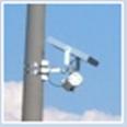
Figure 25. Side-mounted configuration of an FMCW microwave presence-detecting radar illustrating multilane vehicle detection. (Photograph courtesy of EIS, Toronto , Canada ) Application and UsesThe radar sensor may be mounted over the middle of a lane to measure approaching or departing traffic flow parameters in a single lane, or at the side of a roadway to measure traffic parameters across several lanes. Forward-looking wide beamwidth radars gather data representative of traffic flow in one direction over multiple lanes. Forward-looking narrow beamwidth radars monitor a single lane of traffic flowing in one direction. Side-mounted, multiple detection zone radars project their footprint perpendicular to the traffic flow direction and provide data corresponding to several lanes of traffic, but generally not as accurately as can the same radar mounted in the forward-looking direction. Side-mounted, single detection zone radars are typically used to detect vehicle presence at signalized intersections. The types of traffic data received by a microwave radar sensor are dependent on the waveform used to transmit the microwave energy. The CW Doppler microwave sensor detects vehicle passage or count by the presence of the Doppler frequency shift created by a moving vehicle as illustrated in Figure 26. Vehicle presence cannot be measured with the constant frequency waveform as only moving vehicles are detected. Doppler radars can be used to measure vehicular volume and speed on city arterials and freeways, to provide direction dependent vehicle detection, and to provide data to request green phase and extension of green phase for traffic signals. Doppler radars are operated by private companies to measure vehicle speed and subsequently provide traffic flow information to the broadcast media and public agencies. An example of such a radar is shown on the left side of Figure 27. A Doppler radar utilized to provide data for signal timing and for detection of vehicle direction is shown on the right side of the figure. Doppler radars also provide vehicle speed measurement in combination with other sensors that determine vehicle count and presence as was illustrated in the middle and right side of Figure 1.
Figure 26. Constant frequency waveform.
Figure 27. Doppler microwave radar sensors. FMCW presence-measuring radars, such as the models illustrated in Figure 28, are used to control left turn signals, provide real-time volume and occupancy data for traffic adaptive signal systems, monitor traffic queues, and collect occupancy and speed (multizone models only) data in support of freeway incident detection algorithms. Multizone microwave presence-detecting radars can measure vehicle presence and speed and are gaining acceptance in electronic toll collection and automated truck weighing applications that require vehicle identification based on vehicle length. AdvantagesAdvantages of microwave radar include insensitivity to inclement weather, especially over the relatively short ranges encountered in traffic management applications; direct measurement of speed; and multiple lane gathering of traffic flow data. DisadvantagesCW Doppler radar sensors cannot detect stopped vehicles unless equipped with an auxiliary sensor. CW Doppler microwave sensors have been found to perform poorly at intersection locations as volume counters (Kranig, et al., 1997).
Figure 28. Presence-detecting microwave radar sensors. MANUFACTURER AND VENDOR INFORMATION Effective Date: 14 Mar. 2000 Manufacturer name: GMH Engineering Sales representative name(s): Address: 336 Mountain Way Drive Address: Orem , UT 84058 Phone number: (801) 225-8970 Phone number: Fax number: (801) 225-9008 Fax number: e-mail address: priz@gmheng.com e-mail address: URL address: www.gmheng.com URL address: PRODUCT NAME/MODEL NUMBER: Delta Speed Sensor, Model DRS1000 FIRMWARE VERSION/CHIP NO.: SOFTWARE VERSION NO.: GENERAL DESCRIPTION OF EQUIPMENT: The DRS1000 is a small, inexpensive non-contact speed sensor. The output from the sensor is a frequency pulse. Besides vehicle speed, the output can be used to determine vehicle count, distance between vehicles, and general vehicle classification. SENSOR TECHNOLOGY AND CONFIGURATION: The Delta Speed Sensor utilizes Doppler radar technology. The sensor is mounted over the lane of traffic that you wish to monitor. SENSOR INSTALLATION: The Delta Speed Sensor requires a 12 VDC power supply. It should be mounted over the lane of traffic one wishes to monitor. It is aimed at an angle looking up or down the road. The sensor monitors the traffic coming towards or moving away from the sensor. INSTALLATION TIME (Per Lane ): One hour INSTALLATION REQUIREMENTS: 12 VDC and an overhead structure on which to mount the sensor (highway sign, overpass, etc). MAXIMUM NUMBER OF LANES MONITORED SIMULTANEOUSLY: One lane per sensor. PRODUCT CAPABILITIES/FUNCTIONS: The pulse output of the Delta Speed Sensor is proportional to both a speed measurement and a length measurement. The sensor has a frequency output directly proportional to speed. It outputs 211.6 pulses per second for every mile per hour of speed measured (131.5 pulses per second for every kilometer per hour of speed measured). Also, the total number of pulses is equal to the length of the vehicle passing under the sensor regardless of the speed of the vehicle. Every 144 pulses equal one foot of length (470 pulses equal one meter of length or 4.7 pulses are equivalent to one centimeter of length). With this information, one may determine the speed of the vehicles passing under the sensor, the length of the vehicles (as an aid to vehicle classification), the distance between vehicles, and the number of vehicles. RECOMMENDED APPLICATIONS: Anywhere traffic habits need to be monitored inexpensively, without tearing up the roadway, and without expensive maintenance costs. POWER REQUIREMENTS (watts/amps): 9.5 to 16.5 VDC (200 mA @ 12 VDC) POWER OPTIONS: CLASSIFICATION ALGORITHMS: TELEMETRY: COMPUTER REQUIREMENTS: If you wish to input the signal from the sensor into your computer, the computer will need to be able to accept a frequency or counter input. Or, we can provide you with a frequency counter with a RS232 output. They cost $180.00 DATA OUTPUT: 0 to 5 V square waves, differential line driver. DATA OUTPUT FORMATS: SUPPORTING DATA BASE MANAGEMENT SYSTEM: EQUIPMENT AND INSTALLATION COSTS (One-lane and four-lane): One Lane Cost of Delta DRS1000 Speed Sensor $1,595.00 Cost of installation at $100.00/hr labor $100.00 TOTAL $1,696.00* Four lanes Cost of 4 Delta DRS1000 Speed Sensor $6,380.00 Cost of installation at $100.00/hr labor $400.00 TOTAL $6,780.00* *Note: The above prices do not reflect any quantity discounts. STATES CURRENTLY USING THIS EQUIPMENT: Country/State Contact name Telephone number This product is used worldwide. Please contact us for references. MANUFACTURER AND VENDOR INFORMATION Effective Date: 7/17/07 Manufacturer name: Sales representative name(s): ASIM Technologies AG Andreas Hartmann Address: Burgerriet-Strasse 30 Address: ASIM Technologies, Inc. CH-8730 Uznach, Switzerland Xtralis - ASIM 700 Longwater Drive, Suite 100 Norwell, MA 02061 Phone number: +41-55-285 99 99 Phone number: 866-664-ASIM (2746) or 978-667-5207, X 111 Fax number: +41-55-285 99 00 Fax number: 978-667-8247 e-mail address: info@asim.ch e-mail address: ahartmann@asim-technologies.com URL address: www.asim-technologies.com URL address: www.asim.ch/en/contact/usa.php or www.xtralis.com PRODUCT NAME/MODEL NUMBER: MMW 233 FIRMWARE VERSION/CHIP NO.: N/A SOFTWARE VERSION NO.: N/A GENERAL DESCRIPTION OF EQUIPMENT: ASIM K-Band (24 GHz) Doppler radar traffic sensors of the MW 230 series detect vehicles moving into or through their field of view over short to medium ranges. The digital output of the sensor is activated as long as objects within the field of view are moving. When the movement stops, the output resets. Correct alignment of the sensor and a stable mounting structure are mandatory for optimal performance. The detection range of the MW 233 sensor is typically 45 m (150 ft). Turn-on time is 1 s from power on. SENSOR TECHNOLOGY AND CONFIGURATION: The MMW 233 sensor operates as a Doppler radar. The shift in frequency of the transmitted signal caused by a moving vehicle within the field of view of the sensor is used to accurately calculate the vehicle's speed and produce a vehicle passage signal. SENSOR INSTALLATION: The sensor can be mounted overhead or on a pole on the side of the road. The recommended mounting height is 1 to 5 m (3 to 16 ft). INSTALLATION TIME (Per Lane ): INSTALLATION REQUIREMENTS: The supplied standard mounting bracket provides an easy and stable mounting platform for all common applications. MAXIMUM NUMBER OF LANES MONITORED SIMULTANEOUSLY: One PRODUCT CAPABILITIES/FUNCTIONS: The operating modes and other functions of the MW 233 sensor can be selected with DIP switches. The DIP switches are accessible on the connector board. They specify sensitivity, approach direction, minimum detectable speed [4 km/h (2.5 mph) or 8 km/h (5 mph)], and timer on/off function. The timer, when on, automatically activates the output to simulate the arrival of a vehicle if the MW 233 has not changed state for a period of 2.5 minutes. RECOMMENDED APPLICATIONS: Direction dependent vehicle detection, request of green phase, extension of green phase. POWER REQUIREMENTS (watts/amps): 230 VAC, 115 VAC, or 48 VAC. Power consumption is typically <1 W. POWER OPTIONS: Models 231 (responds only to approaching traffic) and 232 operate on 10.5 to 30 VDC or 24 VAC. Power consumption is typically 90 mA @ 12 VDC or 45 mA @ 24 VAC/DC. CLASSIFICATION ALGORITHMS: N/A TELEMETRY: COMPUTER REQUIREMENTS: None. DATA OUTPUT: SPDT relay, 250 VAC / 2 A / 60 W. DATA OUTPUT FORMATS: SUPPORTING DATA BASE MANAGEMENT SYSTEM: EQUIPMENT AND INSTALLATION COSTS (One-lane and four-lane): MW 231 Approach only, Vehicle Motion Detector, Radar: $654.00 (List price/unit) MW 232 Multi-functional, Vehicle Motion Detector, Radar: $784.50 (List price/unit) STATES CURRENTLY USING THIS EQUIPMENT: Country/State Contact name Telephone number Please contact manufacturer for current list of users. MANUFACTURER AND VENDOR INFORMATION Effective Date: 5/10/07 Manufacturer name: Electronic Sales representative name(s): Integrated Systems Inc. (EIS) Mike Ouellette Address: 150 Bridgeland Avenue, Suite 204 Address: 150 Bridgeland Avenue, Suite 204 Toronto , Ontario , Toronto , Ontario , Canada M6A 1Z5 Canada M6A 1Z5 Phone number: (800) 668-9385, (416) 785-9248 Phone number: (800) 668-9385, (416) 785-9248 Fax number: (416) 785-9332 Fax number: (416) 785-9332 e-mail address: info@rtms-by-eis.com e-mail address: mike@rtms-by-eis.com URL address: www.rtms-by-eis.com URL address: www.rtms-by-eis.com PRODUCT NAME/MODEL NUMBER: EIS Remote Traffic Microwave Sensor (RTMS) Models X3 and G4 FIRMWARE VERSION/CHIP NO.: N/A SOFTWARE VERSION NO.: N/A GENERAL DESCRIPTION OF EQUIPMENT: The RTMS is a low-cost, all weather, true RADAR (Radio Detection And Ranging) device, which provides presence, multiple zone, vehicle detection. Its ranging capability is achieved by frequency-modulated continuous-wave (FMCW) operation. The RTMS is capable of detecting vehicle presence and measuring other traffic parameters in multiple zones. The X3 uses a horn antenna, while the G4 incorporates: (1) a phased-array antenna that provides improved spatial resolution and (2) a camera so that the operator can watch the traffic flow as it is detected and analyzed by the RTMS. SENSOR TECHNOLOGY AND CONFIGURATION: The sensor transmits microwave energy and receives a portion of the energy reflected by vehicles and other objects in its path. The nominal 10.525 GHz frequency is varied continuously in a 45 MHz band. At any given time, there is a difference between the frequencies of transmitted and received signals. The difference in frequencies is proportional to the distance between the RTMS and the vehicle. The RTMS detects and measures that difference and computes range (distance) to the target. The range resolution of the RTMS is 2 m (7 ft). It detects both stationary and moving targets. MOUNTING CONFIGURATION: The RTMS is mounted over the roadway in side-fired and forward-looking configurations. Side-Fired: One Model X3 RTMS unit, mounted on a roadside pole and aimed at the side of the vehicles, can monitor up to 8 lanes of traffic up to 60 m (200 ft) away by mapping detection zones to lanes. The G4 can monitor up to 12 lanes of traffic in this configuration. Forward-Looking: One RTMS unit, mounted on an overhead structure, aimed at the front or rear of the vehicles, will monitor one lane of traffic. This configuration provides higher accuracy per vehicle speed measurements SENSOR INSTALLATION: See Installation Requirements INSTALLATION TIME (Per Lane ): Per sensor basis - 30 minutes (approx.) INSTALLATION REQUIREMENTS: The RTMS can be mounted on light standards or poles (Side-Fired) or overhead structures (Forward-Looking). The recommended mounting height is 5 m (17 ft) above the road. Side-fired requires a setback from the first lane monitored. To include all lanes of interest within its antenna beam footprint, the RTMS is set back from the detection zones about 1 m (3 ft) for each equivalent lane monitored (with a minimum setback of 3 m). MAXIMUM NUMBER OF LANES MONITORED SIMULTANEOUSLY: 8 for side fired and 1 for forward looking. PRODUCT CAPABILITIES/FUNCTIONS:
RECOMMENDED APPLICATIONS:
POWER REQUIREMENTS (watts/amps)/OPTIONS:
CLASSIFICATION ALGORITHMS: The RTMS statistically determines the length of an average vehicle. The Long Vehicle Count is incremented by vehicles deemed to be at least three times the average vehicle length. TELEMETRY: Contact closures can be transmitted by optional communication systems (e.g., wireless system). COMPUTER REQUIREMENTS:
DATA OUTPUT: Output information is provided to existing controllers via contact pairs and to computer systems via a RS-232 serial communications port. DATA OUTPUT FORMATS: Asynchronous binary data at 9,600 BPS, 54 byte data packet SUPPORTING DATA BASE MANAGEMENT SYSTEM: Optional data collection and analysis program can format traffic data in Paradox or Dbase. EQUIPMENT AND INSTALLATION COSTS (One-lane and four-lane): STATES CURRENTLY USING THIS EQUIPMENT: Country/State Contact name Telephone Number USA/California TRAVINFO; Bay area USA/Colorado I-25 Colorado Springs , Denver , Grand Junction USA/Florida Various USA/Indiana BORMAN USA/Kentucky TRIMARC USA/Louisiana Baton Rouge I-12 USA/Maryland CHART II USA/New Jersey MAGIC I-80; NJ Turnpike; Garden City Parkway USA / New York NY City (Intersections); Van Wyck Expressway, Long Island Expressway USA/North Carolina CARAT USA/Missouri Interstate - Metro St. Louis USA/Nebraska Counting stations USA/Ohio ARTIMIS: City of Jackson (Intersections) USA/Pennsylvania TOP USA/South Carolina Incident Detection System I 85, 77, and 26 USA/South Dakota Various USA/Virginia Hampton Roads Phases II and III USA/Wisconsin MONITOR USA/Washington State Various MANUFACTURER AND VENDOR INFORMATION Effective Date: 5/10/07 Manufacturer name: Wavetronix LLC Sales representative name(s): Advanced Traffic Products Address: 380 South Technology Court Address: 909 SE Everett Mall Way Lindon , UT 84042 Suite B280 Everett , WA 98208 Phone number: (800) 764-0277 Phone number: (800) 690-4287, (425) 347-6208 Fax number: (801) 764-0208 Fax number: (425) 347-6308 e-mail address: sales@wavetronix.com e-mail: advancedtraffic@advancedtraffic.com URL address: http://www.wavetronix.com URL address: http://www.advancedtraffic.com PRODUCT NAME/MODEL NUMBER: SmartSensor HDTM Model 125 FIRMWARE VERSION/CHIP NO.: SOFTWARE VERSION NO.: GENERAL DESCRIPTION OF EQUIPMENT: The SmartSensor HDTM is a frequency-modulated continuous-wave microwave radar sensor that incorporates auto-calibration and auto-configuration and operates in the above-ground forward-looking and side-firing configurations. It measures vehicle presence, volume, occupancy, and speed. Other traffic flow parameters are available. SENSOR TECHNOLOGY AND CONFIGURATION: The sensor transmits microwave energy and receives a portion of the energy reflected by vehicles and other objects in its path. The SmartSensor HDTM operates at 24 GHz using a 250 MHz bandwidth, giving a range resolution of 2 ft (0.6 m). It detects both stationary and moving targets. SENSOR INSTALLATION: See Installation Requirements. INSTALLATION TIME (Per Lane ): INSTALLATION REQUIREMENTS: The SmartSensor HDTM can be mounted on light standards or poles (Side-Fired) or overhead structures (Forward-Looking). The first lane offset requirement is 6 ft (1.8 m) and the maximum detection range is 250 ft (76 m). MAXIMUM NUMBER OF LANES MONITORED SIMULTANEOUSLY: 10 PRODUCT CAPABILITIES/FUNCTIONS: The SmartSensor HD provides vehicle-based detection, vehicle volume, vehicle presence, indicates lane-changers, per vehicle speed, average speed, 85th percentile speed, lane occupancy, four length-based vehicle classification categories, average headway, and average gap. The SmartSensor HD contains two receive antennas that are separated by a small distance. This dual-antenna design forms a radar speed trap that allows the sensor to measure the time it takes for a vehicle to pass between the two antennas to within a fraction of a millisecond. This time measurement is then used to calculate the speed of the vehicle. Traffic data and configuration settings are stored in flash memory, so the sensor can be remotely configured. RECOMMENDED APPLICATIONS: ITS and arterial monitoring applications. POWER REQUIREMENTS (watts/amps): 9 to 28 VDC, 8 W POWER OPTIONS: See above CLASSIFICATION ALGORITHMS: Vehicle length based TELEMETRY: COMPUTER REQUIREMENTS: Patented auto-configuration process for PC and Pocket PC® DATA OUTPUT: RS 232 and RS 485 communication ports DATA OUTPUT FORMATS: SUPPORTING DATA BASE MANAGEMENT SYSTEM: Wavetronix Data CollectorTM integrates with most ATMS. EQUIPMENT AND INSTALLATION COSTS (One-lane and four-lane): STATES CURRENTLY USING THIS EQUIPMENT: Country/State Contact name Telephone Number Please contact manufacturer for current list of users.
|
|||||||||||||||||||