U.S. Department of Transportation
Federal Highway Administration
1200 New Jersey Avenue, SE
Washington, DC 20590
202-366-4000
Federal Highway Administration Research and Technology
Coordinating, Developing, and Delivering Highway Transportation Innovations
| REPORT |
| This report is an archived publication and may contain dated technical, contact, and link information |
|
| Publication Number: FHWA-HRT-14-023 Date: May 2014 |
Publication Number: FHWA-HRT-14-023 Date: May 2014 |
In an effort to directly determine the effects of cyclic corrosion testing, the cable mockup specimen was deconstructed. Following the completion of cyclic testing, both the aluminum wrapping and centrally located neoprene strap were removed from the cable, the environmental chamber was disassembled, and form work was placed around the cable (see figure 115).
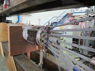
Figure 115. Photo. Disassembled environmental chamber with cable mockup specimen
The tension in the seven jacked strands was released prior to the removal of the cable bands, stainless steel straps, and the subsequent dissection of the mockup cable specimen. It was predetermined that the hexagonal strands of 127 parallel, high-strength steel wires would be removed individually, and each strand's hexagonal shape would be maintained and/or reassumed.
Prior to dissection, the ends of the individual strands were color coded. Both the color-coded left side and the numbering system cable mockup's cross section are shown in figure 115 and figure 116. The wire strands on the surface of the cable (not marked in figure 116) were shaped so as to fill in any voids thereby ensuring a compact circular cross section.
In figure 116, the 20-ft (6.1-m) straightened strands were labeled with a number and a letter indicating the placement and side of the mockup cable when viewed from the jacking end (e.g., 09L). The 35-ft (10.68-m)-long tensioned strands were labeled from bottom to top with numbers 1 through 7. The top and bottom centrally located strands were 20 ft (6.1 m) long and were labeled "T" and "B," respectively.
To differentiate the two ends of the cable specimen, the end where jacking of the strands occurred was called the "South End" while the opposite end was called the "North End." This was done in reference to the geographical orientation of the cable.
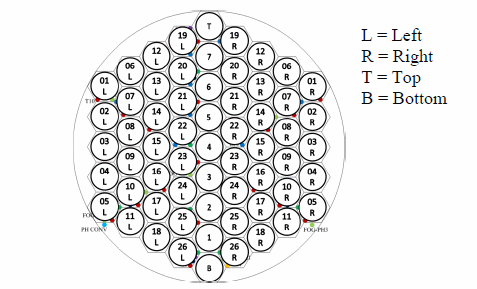
Figure 116. Illustration. Strand labeling
Three wires separated at 120° angles from one another on the surface of each of the 20-ft (6.1-m)-long straight strands as well as individual wires from the cable surface separated at 30° angles were marked for removal and future strength testing.
Once all strands were identified and labeled, the stresses in the tensioned strands were determined and released. In order to de-tension a strand, a jacking beam and two hydraulic jacks that were 6.5 inches (165.1 mm) long and 100,000 lb (45,400 kg) were used (see figure 117). The stress required to completely separate the nut from the framework was recorded by considering the tensile force in the strands using the hydraulic jack's conversion factor of 39 lb/psi (0.689 N/cm2).
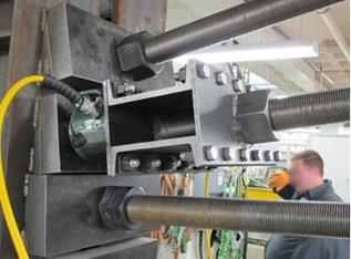
Figure 117. Photo. Jacking beam with hydraulic jacks secured into position
Although the goal was to completely free the cable from all tensile stresses, the stress levels in each strand were not immediately brought to zero, but the unloading was carried out in four steps. The levels of stress in each of the four rounds of de-tensioning are presented in table 15.
Table 15 . Stress levels during cable de-tensioning.
Strand Number |
Remaining Stress (psi) |
~75 Percent Stress (psi) |
Near Zero Stress (psi) |
~Zero Stress (psi) |
|---|---|---|---|---|
1 |
3,230 |
2,460 |
0 |
0 |
2 |
4,600 |
3,450 |
0 |
0 |
3 |
3,940 |
2,970 |
35 |
0 |
4 |
3,800 |
2,740 |
20 |
0 |
5 |
3,875 |
2,920 |
40 |
0 |
6 |
4,620 |
3,460 |
35 |
0 |
7 |
4,700 |
3,532 |
30 |
0 |
1 psi = 6.89 kPa
During the de-tensioning process, strain levels in two wires of strands 4 and 7, and visual observations of the cable reactions were recorded. Figure 118 shows an image of the setup of the strain gauges attached to the cable on strands 4 and 7.
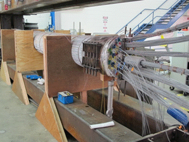
Figure 118. Photo. Strain gauge setup on strands 4 and 7
As stated earlier, the neoprene wrapping used to cover the area at which the wires connected to the sensors exit the cable's cross section was removed prior to the unloading process. Following the unloading, the stainless steel straps (see figure 119) were removed from the cable. The straps were removed from the outside to the inside. The first stainless steel strap was removed at the south end of the cable near the threaded rods. The clamps were unhooked using a screwdriver and then loosened with a hammer until the strap released. This process (see figure 120) was subsequently performed on the north side of the cable and then repeated until all the straps were removed.
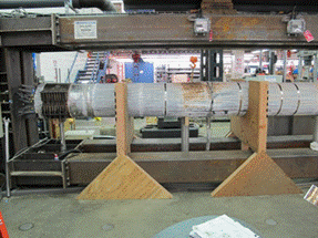
Figure 119. Photo. North end of cable mockup with stainless steel straps
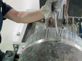
Figure 120. Photo. Removal of south-side strap
Following strap removal, images were taken over the entire length of the cable to document its condition. Several images of the cable from north to south (looking eastward) are presented in figure 121 through figure 124.
Areas of high ferrous corrosion occurring underneath the stainless steel straps were easily identifiable in the south central location shown in figure 123, whereas the north side of the cable experienced little to no ferrous corrosion under the stainless steel straps (see figure 121). This observation can be related to the fact that the cable specimen was slightly inclined toward the south end. The water that penetrated into the inside of the wrapping was able to move toward the south end, favoring the accumulation of water, and consequently the beginning of corrosion, at this end.
Next, both the south and north side cable bands were removed. The bolts and exterior of the cable bands experienced large amounts of corrosion. Wires underneath the cable band remained intact and experienced various amounts of corrosion (addressed in the subsequent section). A before and after image of the area under the north side cable band is shown in figure 125 and figure 126.
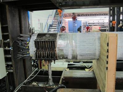
Figure 121. Photo. Stainless steel straps removed from north side of cable mockup
specimen
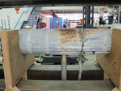
Figure 122. Photo. Stainless steel straps removed from north central side of cable mockup specimen
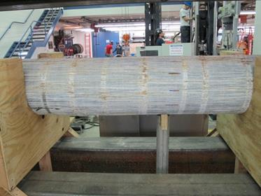
Figure 123. Photo. Stainless steel straps removed from south central side of cable mockup specimen
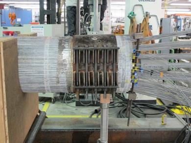
Figure 124. Photo. Stainless steel straps removed from south side of cable mockup
specimen
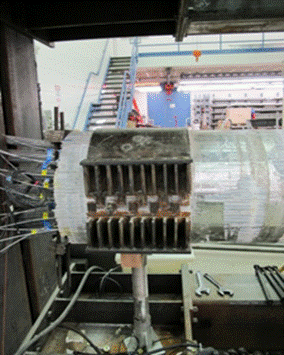
Figure 125. Photo. North side prior to cable band removal
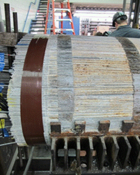
Figure 126. Photo. North side cable end following cable band removal
Removal of the strands started with the removal of the top strands and proceeded toward the bottom of the cable mockup. Because of the difficulties in mounting the long central strands, it was decided to keep the long strands in the loading frame with no tension in them. Upon removal, each strand was first labeled and photographed. Then, a careful visual inspection was carried out for each strand, and pertinent details were reported. Figure 127 and figure 128 show some stage of the cable disassembly. Figure 129 shows the long strands in the loading frame.
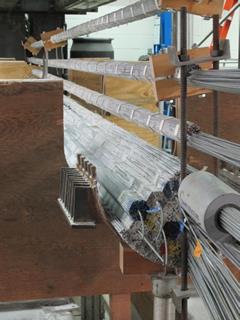
Figure 127. Photo. Cable specimen during disassembly