

Composite Bridge Decking: Phase I Design Report
APPENDIX I: PANEL-TO-PANEL FIELD JOINT REPORT
Description of Tested Specimen
The test specimen for a panel-to-panel field connection was made by joining the edges of two small panels together (FRP tubes and outer wrap) and filling the gap between them with an epoxy grout compound and aggregate, as shown in figure 64. The width of the specimen is 18 inches. The cross section dimensions are shown in figure 65.
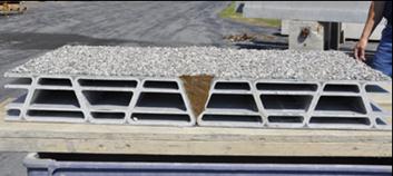
Figure 64. Photo. Panel-to-panel field joint.
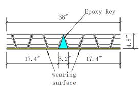
Figure 65. Diagram. Cross section dimensions.
Description of Test Setup
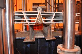
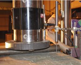
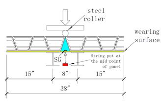
Figure 66 shows the test setup. The FRP panels were loaded using an 18-inch-long steel roller (2 inches in diameter). Two steel I beams (4 inches by 6 inches by 0.2 inches) were used for support between an 8-inch span length (centerline to centerline). Due to the gap created by the wearing surface between the FRP panel and supports, neoprene pads were used on top of the steel supports to more evenly distribute the loading. A 220-kip load cell was used to collect load data. One string pot was placed at the midpoint of bottom face of the specimen (grout key) to measure the vertical displacement. Two LVDTs were placed on the top face of the panel at the centerline of each steel support and 3 inches away from the panel side to measure the deformation of the FRP specimen at the supports; it will be assumed that any deformation at this location will come primarily from the neoprene pads deformation underneath. One strain gage (SG) was installed at the side of the epoxy “key” near the bottom face to measure possible tension strains generated at this location. The specific locations of the string pot, LVDTs, and strain gage are shown in figure 66.
 |
 |
 |
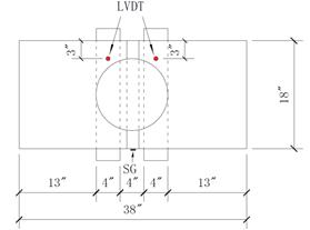 |
Figure 66. Photos and diagrams. End panel connection test setup.
Test Program
The panel was loaded under displacement control. A small cracking sound was heard at 5 kips. A visible crack at the interface between the epoxy key and one of the end panels was observed at a load of 7 kips, as shown in figure 64. A sudden drop of load occurred at 14.7 kips, and the load dropped to 10.7 kips. A large opening of the interfacial crack was observed at this point. The test continued under increasing displacement, and a very small load increase was registered. The crack opening became wider. At a string pot deflection of 0.275 inches and a corresponding load of 11.8 kips, the bond between the epoxy key and the end panel failed, and the specimen separated into two parts, as shown in figure 69.
Figure 70 shows the load-deflection data from the string pot and two LVDTs. The net specimen displacement was taken as the net value between the displacement measured by the string pot and the mean value measured by the two LVDTs. The resulting plot is shown in figure 71. At the maximum load of 14.7 kips, the net displacement of the specimen is 0.06 inches. The net displacement is 0.11 inches at the failure load of 11.8 kips. The negative displacement values in figure 71 may be due to the uneven distribution of reaction forces on the neoprene pads at very small applied loads. It is possible that this caused one of the LVDTs to deform more than the other one and the string pot at the same load level (up to 5 kips of applied load), as shown in figure 70.
Figure 72 shows the load-strain behavior of the epoxy key. It shows an overall linear behavior. The maximum tensile strain at failure load is 534 µε.
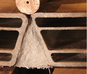
Figure 67. Photo. Crack at load of 7 kips.
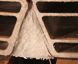
Figure 68. Photo. Crack at maximum load of 14.7 kips.
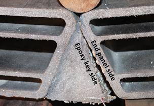
Figure 69. Photo. Failure of the specimen (11.8 kips).
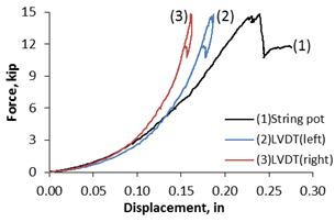
Figure 70. Graph. Load-deflection behavior.
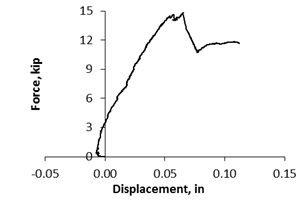
Figure 71. Graph. Net specimen displacement.
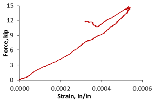
Figure 72. Graph. Load-strain behavior of the epoxy key.
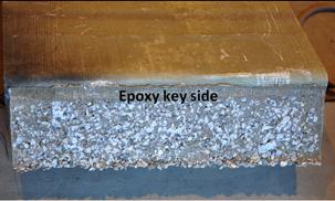
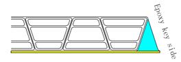
Figure 73 shows the two surfaces of the failed specimen. It should be pointed out that a layer of wearing surface was applied on the surface of the end panel prior to filling out the gap with epoxy compound to form the epoxy key. After failure, it was observed that the aggregates of the wearing surface were almost totally detached from the end panel surface and were primarily attached to the epoxy key side. The end panel failed surface shows a layer of the epoxy from the wearing surface and a small remaining portion of the aggregates. The crack line is shown as a dotted line in Figure 11.
  |
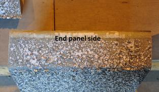 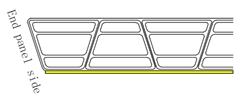 |
Figure 73. Photos. The two failed surfaces.
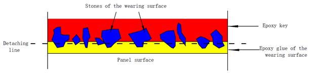
Figure 74. Diagram. Sketch of the crack line.
Conclusion
The FRP end panel connection specimen was built joining two smaller end panels (FRP tubes and outer wrap) and filling their gap with an epoxy compound and aggregate. The specimen failed by a crack propagating at the interface between the epoxy key and one of the end panel surfaces. It can be characterized as a bond failure between the wearing surface and the end panel. The maximum obtained load was 14.7 kips; the maximum tensile strain registered on the epoxy key was 534 µε. The failed surfaces showed that the aggregates of the wearing surface were almost totally detached from the end panel surface and were primarily attached to the epoxy key side.