Previous Chapter « Table of Contents » Next Chapter
A major component of context sensitive design is the final appearance of an engineered slope: how it looks on its own as well as how it fits into the surrounding landscape. To create the best and most natural-looking results, engineers and designers typically use a combination of excavation, as discussed earlier in Chapter 3, and rock slope/landscape integration, which uses physical and cosmetic alterations to modify the shape of a slope and give it a more natural appearance by mimicking the surrounding topography.
In some cases, safety or cost concerns make it impossible to achieve a completely natural look. However, in any case, the engineer and the contractor should strive to develop a slope that is safe, looks natural, and satisfies the interests of all project stakeholders.
Table 7 provides an overview of the most common rock slope/landscape integration techniques, along with the advantages and limitations of each. Each procedure is discussed in detail below.
Physical alterations, which remove or reposition sections of rock and/or soil, are an effective way to improve the appearance and stability of a slope.
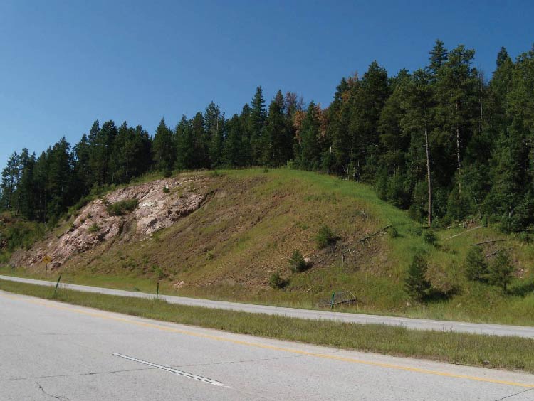
Major slope warping is the process of rounding (or sculpting) the lateral ends of a cut slope to smooth its transition to the surrounding terrain as shown in Figure 27. It can be accomplished through blasting/ripping, scaling, and other excavation techniques, which were discussed in greater detail in Chapter 3.
Although this technique can be used on any rock type, it generally produces the best results in hard rock. Creating a lower angled slope on the ends of a cut increases the exposed surface area of the rock there, resulting in faster weathering rates compared to rock in steeper sections of slope.
Major slope warping has become a common practice on highway projects, industrial parks, golf courses, landscaped open space around corporate buildings, and other such features. The disadvantages of this technique include increased cost due to a larger amount of required excavation and drilling, additional right-of-way, and increased long-term maintenance for scaling on slopes with erodible materials (as with any rock cut, it is very important to thoroughly scale the slope immediately after excavation and periodically thereafter to remove any loose rock that could potentially dislodge).
Table 7. Overview of rock slope/landscape integration techniques.
| Procedure | Description | Best Rock Types/advantages | Limitations/disadvantages |
|---|---|---|---|
| Major Slope Warping | Rounds the ends of the cut to smooth the transition between the rock cut and the natural terrain. | Can be used on any rock type. Best used on inside turns of the roadway and ridge and valley systems. | Flatter portions of the slope will be more exposed to weathering and erosional processes. Requires blasting procedures capable of angled borings. Slope ends are visible to motorists for a longer time. |
| Expanded Slope Rounding | Rounds the crest of the cut slope to smooth the transition to the natural terrain. | Can be done on any rock type. Best on slopes with a minimal colluvial cover. The crest is often an area of increased weathering and blasting damage, removing it reduces rockfall hazard. | Areas of thick colluvial cover will require soil excavation techniques and possible access problems. |
| Drainage Intercepts | Specifically designed to transition topographical low areas to high areas by gradually decreasing the slope angle transiting to the low area. | Can be used in any rock type. Combining with expanded slope rounding and major slope warping will improve aesthetics. | Blasting procedure must be capable of different angles of borings. Rockfall launching features may result if the transition section is rough. Slope ends are visible to motorists for a longer time. |
| Ditch Width Expansion | Provides slope variation longitudinally along the slope and often extends throughout the slope height. Works well in areas of long monotonous cuts. | Can be used on any rock type. Ditch width variations can be used to hide drill hole traces. Effective in reproducing natural undulations in the slope. | May be difficult in moderately to highly fractured rock because of kinematics. Blasting procedure must be capable of variable angled borings. Can cause rockfall launching features. |
| Slope Angle Variation | Varies the slope angle laterally along the slope to accentuate prominent geological features or differences in weathering rates. | Design changes with rock type. Layered rocks result in a stair step pattern while massive rock depends on intrusions and competency variations. Very effective in sculpting the rock. | Very dependent on geological features. Rockfall prone areas can cause problems due to launching features. Often increases time of construction. |
| False Cut Embankment And Median Berm | Adds topography along the shoulder or median of divided highways for screening, variety, and areas of re-vegetation and landscaping. | Adds topography along the shoulder or median of divided highways for screening, variety, and areas of re-vegetation and landscaping. | Designer must ensure the barrier will not launch or overturn errant vehicles. Should not be left with an excessively regular surface. |
| Rock Staining | Stain is applied to the rock surface to help blend the freshly cut slope color to the natural weathered rock color. | Stain is applied to the rock surface to help blend the freshly cut slope color to the natural weathered rock color. | Must test several stains to find the correct color that fits the natural conditions. Slope should be thoroughly scaled and can be power washed to remove loose material. |
Slope warping can be designed using a few different methods: using a slope offset and angle table, contour grading plans, or an equation relating cut slope height, distance, and slope angle (Cummings 2002). The desired transition from a steeper to a shallower slope angle is typically shown in the cross section portion of the construction drawings. The transition section is shaped like a circular segment, with the slope angle gradually decreasing from the angle of the main cut face to that of the natural slope. It's important to follow a common radius in the transition section (i.e., the area from the excavated slope face to the natural slope) because the viewshed is always tangent to the slope when seen from the side.
After excavating the main slope up to the transition section, the contractor will start decreasing the slope angle along the designed circular segment until the natural slope angle is reached. Conventional excavating equipment is generally used to achieve the desired effect. In hard rock major slope warping generally requires drilling angled borings (with equipment such as a track rig), blasting/ripping, and scaling. Following the excavation, revegetation in the transition sections and/or slope face provides additional natural enhancement and helps blend the cut slope into the natural environment even more.
Expanded slope rounding helps to blend the crest of a cut slope into the natural terrain by sculpting the upper portion of the cut, shown in Figure 28, using standard excavation techniques. In rippable material, this is typically accomplished with an excavator; in hard rock, the contractor will use explosives.
Expanded slope rounding can be done on a variety of rock types. It does not produce slope launching features, as the angle of the cut slope in unchanged, and does not require any blasting techniques other than those used in blasting the final finished rock face. Disadvantages include increased cost of excavation, blasting, and the potential for a small increase in right-of-way. Expanded slope rounding also requires thorough scaling after initial excavation and periodically thereafter.
Slope rounding is a very effective way to enhance slope aesthetics in areas where motorists or pedestrians have an unobstructed or extended view of the slope crest. It also provides an opportunity for creating ledges and encouraging revegetation. In many cases, the crest is the most weathered and blast-damaged section of the slope; therefore, removing part of the crest through expanded slope rounding helps to reduce rockfall and long-term erosion problems.
Figure 29 shows a slope on which slope rounding was not constructed. Note the areas of overhanging topsoil and vegetation mat, caused by excessive erosion at the top of slope.
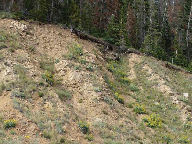
Figure 29. Photo. Expanded slope rounding can prevent this type of erosion and overhang.
Currently, the FLHD shows the desired degree and location of slope rounding for any given project in the Typical Sections of standard construction drawings. Conceptual drawings depicting slope rounding and other techniques are provided in the Embankment Benching and Serrated Cut Slope special drawing, which is included in most FLHD projects.
Rounding generally requires drilling, blasting, excavation, and scaling equipment. When explosives are required, controlled blasting should be used to minimize the damage to the final slope face. In slopes with hard bedrock at the brow, a row of "satellite" holes can be drilled behind the main slope trim line, then lightly loaded and detonated to reduce backbreak and fly rock.
If the slope has a substantial amount of unconsolidated material along the brow, the material should be removed with a track-mounted excavator or by hand. Long-reach excavators are typically used in areas with steep terrain. Using large radii to define the rounded slope crest in the transition area is visually more appealing than using smaller standard radii, as the larger radii generally appear more natural.
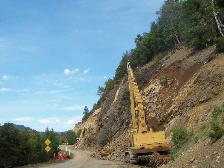
Drainage intercept laybacks are a modification of major slope warping specifically designed to transition from the typically uniform cut slope to natural recessed areas or swales (the recessed area does not need to be actual water drainage). Drainage intercept laybacks are extremely effective visually because they break up the uniformity of both small and long sections of the cut slope to more closely resemble a natural slope shown in Figure 30. In the transition zone between the cut slope and the swale, the slope angle is decreased and the slope crest is rounded back as it would be in expanded slope rounding. Ledges can be incorporated into the design to help mitigate rockfall and to facilitate revegetation.
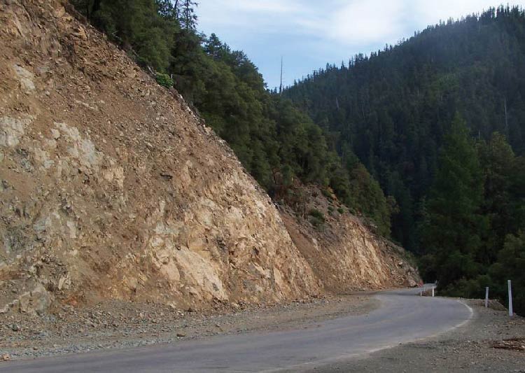
Figure 30. Photo. Drainage intercept layback cut into a slope, Hyampom Road, California.
Constructing drainage intercept laybacks is cost effective because it does not require a large amount of additional excavation. Also, because there is only a slight slope angle difference between the topographically high and low areas, it is effective even in highly fractured formations where the discontinuity orientations limit the slope angles that can be constructed.
In the area of the existing depression, the slope angle between the ridge area and the drainage is gradually reduced. The ditch width can also be widened for additional visual enhancement. The desired slope angle variation can be shown in the cross sections, but because this is a matter of the owner's criteria and choice, most successful projects require oversight by the owner's representative to achieve the appropriate amount of layback at each drainage feature.
The equipment used to construct drainage intercept laybacks is similar to that used in slope rounding, as described previously. In addition, drainage intercept laybacks require a drill rig capable of drilling angled borings, and may also require explosive, excavation, and scaling equipment. If the slope material is softer bedrock or a slope cover over bedrock, a conventional excavator and/or hoe ram can be used. Good accessibility to the top of the slope is another requirement.
In ditch width variation, engineers use blasting, ripping, scaling, and other excavation techniques to alter the width of a ditch that runs down the cut slope face. Ditch width variations are used in long monotonous cuts, at geologically significant locations, and at drainage intercepts. They are also used in places where the ditch is much wider at the center of the slope than at the top and bottom, which creates an unnatural concave shape in the center of the cut slope.
Figures 31 and 32 show examples of ditch width variations made along a vertically cut, presplit slope. The expansions add variation to the otherwise monotonous slope face, provide a wider catchment area for rockfall, and help camouflage the exposed drill hole traces.
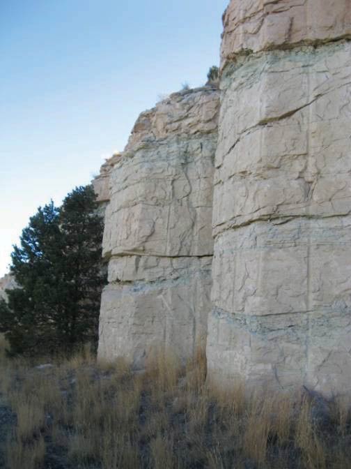
Figure 31. Photo. Ditch width variation used to break up the slope face and mask drill hole traces.
Slope and slope crest geometry are key factors in designing ditch width variations. In addition, because expanding ditch width can change the slope angle, the designer must also consider the structural characteristics of the rock mass in order to avoid constructing a potentially unstable slope (a scan line survey and kinematic analysis using an equal angle or equal area net will reveal potentially hazardous slope angles). When varying the slope angle, the blaster should gradually change the borehole inclination to prevent the intersection of two different slope angles, which could make the slope appear unnaturally flat.
When designing ditch width variations, the slope designer also should observe the natural slopes in the area and try to replicate their natural variations. For example, sedimentary formations often form steep, smooth-sided cliff faces, while igneous rock usually forms a much more irregular gradient.
The slope should be excavated from the top down and/or from the roadway inward. The slope should be thoroughly scaled after excavation to remove any potentially unstable material. If blasting is required, the blast plan should accommodate the variations in the slope and ditch. To reduce backbreak, blasting should be set up to follow the natural rock structure instead of with presplitting or line drilling methods. Ditch width variation requires drilling rigs capable of drilling angled borings, as well as excavation, blasting/ripping, and scaling equipment.
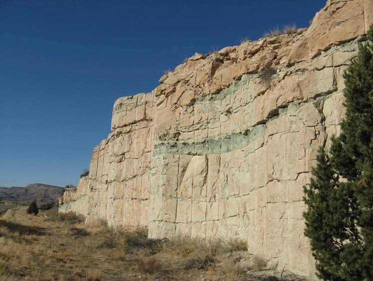
Figure 32. Photo. Ditch width variation can camouflage blast scars and drill traces.
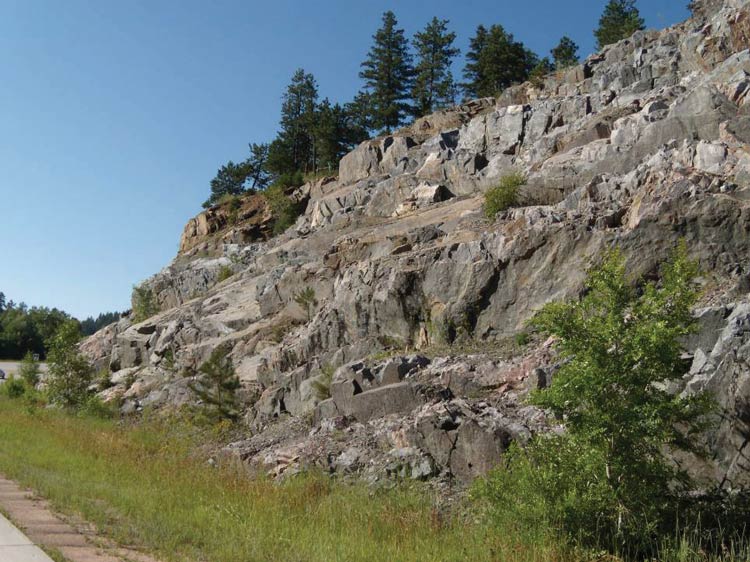
Slope angle variations are used to break up the planar look of a blasted cut slope, see Figures 33 and 34. They can also be used to accentuate prominent geological features (such as intrusive units and variations in rock weathering rates); to replicate the roughness of the surrounding terrain; and to sculpt knolls, minor ridges, and drainages.
Engineers typically use rock mass discontinuities or existing seams, more resistant intrusions/rock units, and geologically significant areas to shape the cuts. If rockfall potential exists, mitigation methods such as rock bolts, expanded roadside ditches, or mesh may be needed as discussed in Chapter 5.
Figure 33 illustrates the effective use of slope angle variation to simulate the natural weathering patterns in interbedded sandstone, siltstone, and claystone. Special blasting and layout staking techniques were used to direct the contractor to the desired cut slope configuration along the corridor.
Slope angle variations can be most easily shown in the plans through a slope exception table or tabulation of station and offset to the slope toe and catch point, which is the point where the excavated slope meets the natural slope (Cummings 2002). Designers typically look to the surrounding natural rock outcroppings to determine the ideal degree of slope angle variation.
Because different rock types have different fracturing and weathering patterns, there is no universal design for slope variations. In general, rock formations that are good candidates for this technique are cliff-forming units (as opposed to slope-forming units), which can be seen in the surrounding topography as fairly steep exposed rock faces with easily discernable rock texture.
The excavation should proceed in a top-down fashion, and any loose rocks should be removed and the slope thoroughly scaled after completion to remove any potential rockfall sources. For added visual enhancements, vegetation (trees, grasses, shrubs) and/or boulders can be placed on benches or along the roadside.
Slope variation requires drilling equipment capable of angled boring, such as a track rig or hand drills, which can be used in competent material, or ripping equipment, which is a better choice in softer or fractured rock. Scaling equipment will also be required.
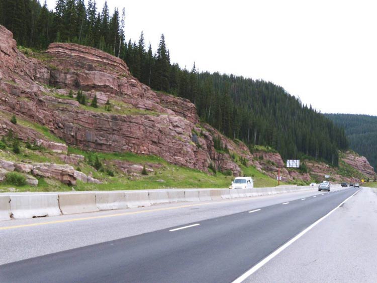
Figure 35 shows an example of slope angle variation and rock sculpting in a metamorphic rock. The existing rock structure was used to control the blast damage and shape the final configuration of the slope. Following each blast, excess and loose material was removed down to the more stable rock units. The overall slope angle was constructed at a 1:1 slope, with steeper zones nearby providing the appearance of a naturally exposed rock outcropping.
Rock slope/landscape integration also can involve cosmetic changes to the slope, including the application of stain to help blend the areas of cut rock into the existing terrain.
Rock staining products, which are sprayed or dripped onto the fresh rock face, can bring the cut rock to its natural, weathered color within weeks. Some products are pigmented stains, while others create the new color by leaching minerals from the rock or through photoreactivity.
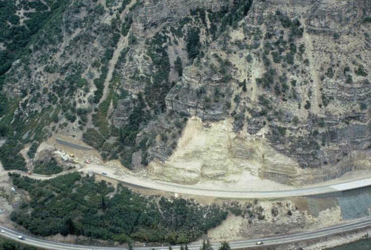
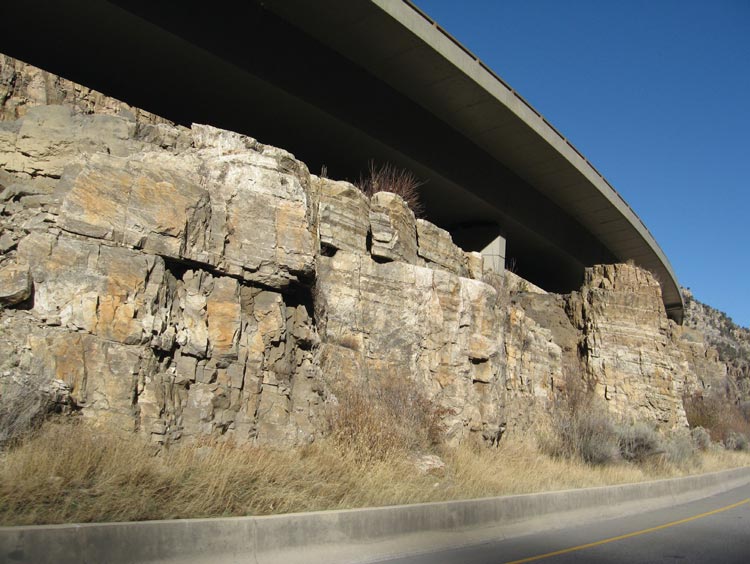
Before staining, the engineer should conduct several test sections on the excavated rock cut to determine the type of stain that will create the best match with the surrounding rock. Not every stain is compatible with all types of rock, and the final color depends on stain concentration and formulation. Several coats of stain may be required if the fresh and weathered faces look very different. Stain applied to highly fractured and/or absorbent rocks tends to fade; meaning these types of rock may not be good candidates for staining. The designer should use choose a color that matches the surrounding rock, including areas of natural dripping and streaking. Areas that feature vegetation (including lichens and moss) typically cannot be accurately simulated with staining. Figure 36 is an aerial oblique of a rock excavation shortly after construction and Figure 37 is a photograph of the completed slope from the roadway. The rock face was stained to help create a cut slope that is indistinguishable from the surrounding natural rock.
Rock staining is a very effective and cost efficient way to quickly blend the color of fresh or faintly weathered excavated rock faces to that of the surrounding natural rock faces. This can create significant visual enhancements in both the short- and long-range perspectives.
Rock staining requires oversight by the owner or qualified expert during the application.
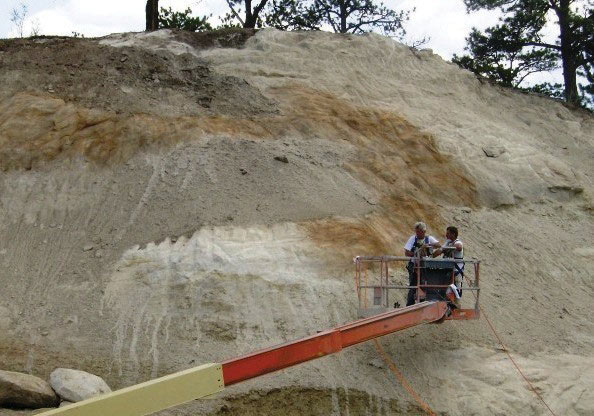
The slope should be dry and all loose material and vegetation removed before stain is applied. In many cases, the slope face is pressure-washed to remove fine-grained particles that would inhibit the stain penetration. Equipment required to perform rock staining usually includes an air compressor, hose, rock stain, application nozzle, and a man lift large enough to reach the top of the slope.
Figure 38 shows the application of rock stain using a hand-held sprayer and man lift (or crane).
Stay up to date
Sign up for announcements on grant opportunities, training, and webinars.