Precast Bent System for High Seismic Regions: Laboratory Tests of Column-to-Drilled Shaft Socket Connections
DESIGN OF TEST SPECIMENS
Two drilled shaft-column connection specimens (DS-1 and DS-2) were designed, constructed, and tested at the University of Washington. The design and construction of the specimens are described in this chapter. The detailed design drawings are shown in appendix A, and the material test reports are shown in appendix B.
Configuration of Test Specimens
The two specimens each consisted of a precast column, embedded in a cast-in-place drilled shaft, which in turn was anchored to the testing rig by a cast-in-place base. For both specimens, these three components had the following geometries:
- Precast Column: The cantilever-precast columns had a diameter of 20 inches and a span of 60 inches, resulting in a shear span-to-depth ratio of 3.
- Drilled Shaft: The cast-in-place drilled shaft had a diameter of 30 inches and a length of 31 inches, which slightly exceeded the length of the transition region (28 inches).
- Base: The drilled shaft was embedded in a 74-inch by 48-inch by 24-inch cast-in-place base to anchor the specimen to the base of the testing rig.
The test specimen dimension and reinforcement were scaled (1/3.6) from a prototype, as shown in table 1. The diameter of the prototype column and shaft were chosen as 6 feet and 9 feet, respectively, to make the transition region more critical. The scale factor was chosen as 3.6 to match the 20-inch diameter of column specimens tested by previous researchers.(10,14)
The only difference between specimen DS-1 and specimen DS-2 was that the amount of spiral in the column-to-shaft transition region was reduced by half in DS-2.
| Prototype | Specimen (Scale factor: 1/3.6) |
|
|---|---|---|
| Column diameter | 6 ft | 20 in. |
| Shaft diameter | 9 ft | 30 in. |
| Column cover | 2 in. | 0.6 in. |
| Shaft cover | 6 in. | 1.7 in. |
Design of Prototype and Test Columns
The test column was designed to have a reinforcement ratio of 1 percent, which was provided using 10 No. 5 bars. The transverse reinforcement ratio was chosen as 0.82 percent to be consistent with previous tests done at the University of Washington. (See references 5, 8, 10, and 14.) Thus, the transverse reinforcement was 3-gauge (0.244-inch-diameter) spirals at a pitch of 1.25 inches. All reinforcement was assumed to be ASTM A706, and the nominal concrete strength was assumed to be 6 ksi.
The flexural strength of the column in the specimens was found by performing moment-curvature analysis using the Mphi18 program developed at the University of Washington. Steel properties were modeled according to the AASHTO Seismic Guide Specifications, and the confined concrete properties were modeled using Kent and Park's model.(15) However, the values of the confined concrete strength, the strain at peak stress, and the ultimate compression strain were generated from the properties of the confinement reinforcement using Mander's formula, rather than using the values recommended by Kent and Park.(16,17) Details of the moment-curvature analysis are shown in chapter 6. The constant axial load applied in the column was 10 percent the axial load capacity of the column (=159 kips). Using the above moment-curvature program, the ultimate moment capacity of column cross section was 3,507 kip-in.
The embedment part of the column (28 inches) had an octagonal shape and was circumscribed inside the circular section of the upper part of the column. The outside surface was intentionally roughened with a saw-tooth detail similar to the one required by the WSDOT BDM for prestressed girders. The dimension of the saw-tooth detail was used in the shear-friction design procedure proposed by the AASHTO LRFD. All dimensions designed for the prototype were scaled down to specimen dimensions.
The ends of the longitudinal column reinforcement were terminated with rebar end anchors, instead of using the more conventional detail of bending the longitudinal bars outwards into the foundation. This kind of anchor helped to reduce the development length of longitudinal reinforcement and made the connection between the precast column and cast-in-place drilled shaft more constructible.
Design of Specimen Column-to-Drilled Shaft Connection
The embedded length of the column in the drilled shaft was based on the scaled-down non-contact lap splice length of the shaft prototype according to the WSDOT BDM. This length calculation was proposed by McLean and Smith.(18) The embedded length is equal to , where length of noncontact lap splice, lap splice length required by AASHTO LRFD 5.11.5.3 or (for a Class C lap splice) where is the development length of the larger bar, and distance between the shaft and column longitudinal reinforcement.
The shaft longitudinal reinforcement was designed to form a plastic hinge in the column. Therefore, the yield moment of the shaft had to be larger than the moment at the base of the shaft (5,319 kip-in.) due to the overstrength moment and shear from the column above. Calculation showed that using 30 bundles with 2 No. 3 bars per bundle for the longitudinal shaft reinforcement in the test specimens would satisfy the requirement.
The shaft spirals were designed as non-contact lap splices according to the WSDOT BDM, sections 7.4.4 and 7.8.2. Accordingly, the spacing for spiral was given as shown in figure 2.
In addition, the spirals within non-contact lap splice zone should not be less than No. 6 at 6-inch pitch in the prototype. However, the spacing should not exceed 9 inches.
To satisfy all these requirements, No. 6 spirals at 8-inch pitch were used in prototype, which would be a bundle of two 9-gauge wires (0.148-inch diameter) at 3-inch pitch. However, in specimen DS-2, to increase the likelihood of failure in the connection, the amount of spiral was reduced by half to one 9-gauge wire at 3-inch pitch. The shaft reinforcement details are summarized in table 2.
| Item | Prototype | DS-1 | DS-2 |
|---|---|---|---|
| Longitudinal reinforcement | Two No. 11 bars per bundle, total of 30 bundles | Two No. 3 bars per bundle, total of 30 bundles | Two No. 3 bars per bundle, total of 30 bundles |
| Spiral | No. 6 at 8-in. pitch | Two 9-gauge wires at 3-in. pitch | One 9-gauge wire at 3-in. pitch |
WSDOT BDM section 7.4.5 requires three turns of the wire at the end to terminate the spiral. This is an anchorage requirement. However, in the case of the column-shaft connection, it was believed that the extra turns also provided extra strength at the top of the transition region.
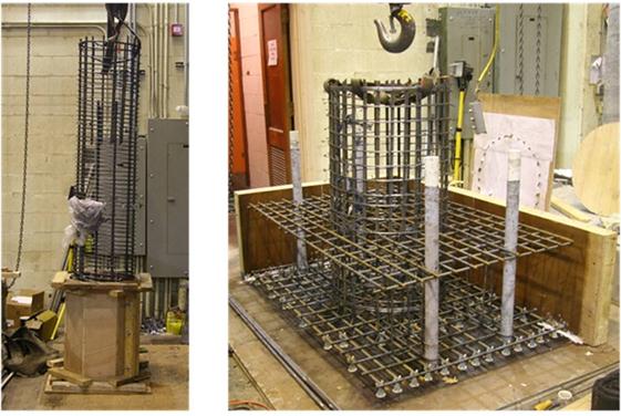
The bottom of the shaft connected with a 74-inch by 48-inch by 24-inch cast-in-place footing to attach the specimen to the testing rig. The longitudinal bars of the drilled shaft were hooked at the bottom mat of the footing, as shown in figures 3 and 4.