Previous Chapter « Table of Contents » Next Chapter
To design and construct natural-looking rock slopes, the designer/engineer and contractor must first consider the following questions (Maher et al. 2005):
How will the proposed transportation improvement affect the general physical character of the area surrounding the project?
Does the area to be affected have unique historic or scenic characteristics?
What are the safety, capacity, and cost concerns of the community?
Answering the above questions will help the engineer/designer address the basic issues of CSS in the early stages of roadway layout or mitigation method.
The critical first step of CSS is assessing the surrounding area-the context of the project-and then designing the rock slope to follow the area's natural characteristics. Rock slope context can include such factors as weathering patterns, fracture planes, vegetation, rock/slope color, and roadway layout. For example, the context of Zion National Park in southern Utah features steep- walled, light- to reddish-brown canyons with sparse vegetation and numerous rock outcroppings. Thus, an engineer following CSS would design cut slopes that were steeply sloped, colored to match the natural staining, and re-vegetated with a native seed mix. In contrast, the context in Washington's Olympic National Park and other areas of the Pacific Northwest includes heavily vegetated, moderately sloping landscape. Cut slopes designed to follow CSS principles in this area would be laid back, with rounded transitions between the cut area and the natural slope; the designer might also use revegetation and rock coloring to help blend the cut face into the natural terrain.
The design process can be broken into five distinct steps: assessing slope stability, selecting the most appropriate excavation technique(s), designing safe and aesthetically pleasing rock cuts, determining visual prioritization, and developing any necessary stabilization and/or rockfall protection methods. Designers must also establish consensus among stakeholders throughout the design process.
Engineers analyze slope stability for rock (or predominantly rock) slopes by using the scan-line survey and stereographic analysis technique, often referred to as a kinematic analysis. A scan- line survey evaluates the dip, orientation, spacing, and surface condition of the discontinuities in a section of rock. A kinematic analysis considers the potential for movement in a slope-any motion that's geometrically possible-and determines the possibility that a rock mass might move or slide.
If a proposed slope angle presents a kinematically possible mode of failure, it should be analyzed using a stability analysis method (i.e., limit equilibrium analysis), which compares the forces that will be resisting failure to those that could be causing it. The ratio between these two sets of forces is the slope factor of safety, or FS.
Geology is the main consideration in determining the best excavation technique(s), slope design, stabilization, and protection measures for a rock slope. For engineers and other rock slope designers, some of the key components of a slope's geology are its orientation and angle and the type and structure of rock it comprises.
Slope Orientation and Angle:
To determine the inclination and orientation, or "attitude," of a slope or any other type of plane, geologists typically measure two angles: strike and dip. The strike is defined as the line of intersection between the slope and the horizontal plane. Identifying the strike tells the engineer the precise direction that the slope is facing. Strike is measured in degrees and bearing (compass direction) relative to north; for example, a slope with a strike of N45°E is oriented-45° east of due north. The dip is the maximum angle, measured from a horizontal plane, of the surface that is perpendicular to the strike. An apparent dip is any other dip in the slope that's not perpendicular to the strike line (and therefore not as steep).
Discontinuity orientation is most conveniently expressed as dip and dip direction for rock slope engineering purposes. The dip direction is the direction of the horizontal trace of the strike line measured clockwise from north. The orientation of the plane can be completely defined by five digits. Dip is expressed in 2 digits and dip direction in 3 digits. By always writing dip direction as three digits, there can be no confusion as to which set of figures refers to dip direction. For example, a discontinuity with a dip of 55 degrees and an azimuth orientation of 90 degrees would be expressed as 55/090. A discontinuity with a dip of 5 degrees and an azimuth orientation of 310 degrees would be expressed as 05/310. This is illustrated in Figure 1.
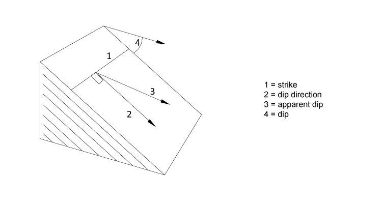
View larger version of Figure 1.
Rock Type and Structure:
Slope stability also depends heavily on the type and condition of the rock and soil that comprise the slope. In slopes consisting primarily (or entirely) of rock, the biggest concern is the geologic structure of the rock: its discontinuities-bedding surfaces, joints, foliation, faults, and other natural defects-and the location and orientation of those discontinuities. It's the geometric interrelationship of the rock mass and its discontinuities that determines, to a large part, the stability of a slope.
In all but the rare case of a completely unfractured rock unit, the rock mass can be considered a three-dimensional assemblage of rock blocks delineated by sets of discontinuities. These discontinuities can occur as unique, randomly oriented features or repeating members of a discontinuity set. This system is sometimes referred to as the structural fabric or characteristic of the rock mass. In most cases, engineering properties of the fractured rock mass-strength, permeability, and deformability-depend more on the discontinuities than on the properties of the intact rock.
For example, geologic structure can influence many short-range aesthetic features, such as slope texture and roughness, as rock with multiple fractures (less than 1/3 to 1 meter or 1 to 3 feet apart) is likely to show blasting/machine scars and other unacceptable levels of surface damage.
For extremely weak rock, engineers use classic soil mechanics principles for defining the FS of the rock mass. Methods that use soil mechanics principles are limit equilibrium approaches such as the method of slices (e.g., Bishop Method, Spencer-Wright Method, and Morgenstern-Price Method). There are several different computer programs for analyzing slope stability, excavation design, and geotechnical applications.
CSS principles require engineers to determine the best excavation technique(s) for the project, considering the type of rock to be removed, the end use of the material, and the cost and context of the roadway. Different rock types require different types of excavation. In many cases, the excavation method will influence the dimensions and stability of the final slope and the rockfall mitigation strategy. Different types of excavation will also produce varying levels of superficial damage, such as drill-hole traces and machine scars. Thus, excavation method(s) must be agreed to by all project stakeholders. These excavation methods are addressed in Chapter 3.
To ensure safety, the angle (or angles) of the rock cut should be developed in accordance with the results of a kinematic analysis. All relevant modes of failure that may occur with an improperly cut slope angle must be considered. If a slope is cut at an angle that allows for one or more of the possible modes of failure, it may require expensive mitigation and maintenance for many years after the initial construction. Designing a slope in a manner that takes into account all relevant failure modes will reduce the stabilization and/or protective measures required, which will minimize costs, and, if context is properly considered, will improve the aesthetics of the slope.
Designing a natural-looking rock cut can be challenging if the designer is not familiar with current design practices and proper techniques for stabilization and protection. Construction drawings and specifications should include examples of the proposed layout of the rock cut in the form of pictures, sketches, and acceptable/unacceptable cut slope configurations and excavation techniques. Flexibility is essential in context sensitive design because the heterogeneity of geological formations and the changing topography along the length of a rock cut often require on-site design decisions. Communication between the contractor and the contracting agency, before and during construction, is paramount in creating rock cuts that are safe and aesthetically acceptable to all stakeholders.
Visual prioritization is the process of determining which aesthetic enhancements will truly enhance the visible aspects of the roadway and those that will result in needless expense. In many cases, visual prioritization is performed by a landscape specialist working as part of a multidisciplinary highway design team and in close coordination with the land management agency. Visual impacts should be considered according to their location as well as the duration and distance of motorist and non-motorist view (i.e., how long a person will see the feature and from how far away). In general, the most significant visual impacts to the highway user are those that will be apparent for longer than approximately 10 seconds when driving at the posted speed limit.
When prioritizing visual impacts, the designer must consider both the short- and long-range viewsheds (Cummings 2002).
The short-range viewshed includes slope features that are visible within short distances, normally in the motorist's final approach or while they are passing the slope. Short-range features include slope texture, roughness, revegetation, stabilization methods, blasting/machine scars, and certain rockfall protection structures (e.g., rockfall draperies). While these features all contribute to the overall aesthetics of the slope, they typically require careful evaluation against duration of motorist view to avoid needless expense. The posted speed along a roadway and the location of the slope with respect to the roadway are main factors when evaluating the duration of view.
Motorists are less likely to notice intricate slope texture or rock bolts while traveling at high speeds past a slope. Short-range features located on the inside of a curve, near the slope crest, parallel to the roadway, or on the slope-end opposite of traffic direction are less likely to be noticed than features located on the outside of curves, at eye level, on the slope-end facing traffic direction, or in straight roadway sections that offer extended view times.
The long-range viewshed includes features that are visible to motorists at some distance from the slope, even while traveling at high speeds. Long-range features include slope variations, cut slope angles, and rockfall protection structures such as rockfall barriers and fences. Probably the most effective method of increasing rock cut aesthetics is fitting long-range features into the landscape by mimicking natural landform processes and by creating proper transitions between cut slopes and the natural terrain. Areas with long monotonous cuts, slopes with an extended view, highly variable topography, and geologically significant areas are good candidates for long-range features.
If a slope cannot be stabilized by proper slope angle selection, slope stabilization measures normally provide the most cost-effective and aesthetically pleasing means of rockfall mitigation. Stabilization measures work to reduce or inhibit rockfall by either removing the unstable section(s) of rock or providing internal or external support to the rock mass (either increasing the resisting forces in the rock mass or decreasing the driving forces).
Engineers must review potentially unstable slopes or areas of rockfall and consider all applicable stabilization methods in terms of cost, feasibility, stability improvement, and aesthetic impacts, then perform limit equilibrium stability analyses with the proposed stabilization measures until the slope is at the AASHTO-recommended factor of safety (FS).
In areas of high rockfall risk or where stabilization is not feasible, engineers must evaluate the effects of rockfall protection methods on potential impact energies, bounce height of rockfall, maintenance requirements, cost, and aesthetics. The use of rockfall protection methods accepts the reality that rockfall will occur and strives to protect structures by stopping, diverting, or controlling it.
Protection structures are normally placed at the toe of the slope and act to either stop the rockfall or deflect it from the roadway. A common feature of all protective structures is their energy- absorbing characteristics. Properly designed protective structures are able to absorb repeated high-energy rockfall impacts.
Avoidance measures may be a valid option if the cost of stabilization, protection, and maintenance is greater than the avoidance cost. Avoidance should always be considered in very hazardous areas, although it can be an expensive option. Avoidance options include elevating the roadway, tunneling, or relocating the roadway. An in-depth discussion of avoidance structures and design parameters is outside the scope of this report.
Effective CSS designs also require consideration of stakeholder concerns, particularly those involving safety and cost. One of the challenges in any type of rock slope design-particularly a natural-looking rock slope-is developing a cut slope that meets long-term stability objectives.
For example, rock slopes that are cut near vertical typically look more natural, but they are less stable than cuts that are laid back at a specific slope ratio that is not as steep as the surrounding terrain. Thus, it's imperative that the designer/engineer establish an understanding with the stakeholders that addresses all of the aesthetic, safety, and cost considerations of the improvements. A successful context sensitive project involves gathering all stakeholders early in the scoping and design process to prevent confusion, disagreements, and delays that may develop later.
Once established, the desired slope parameters should be included in the bid document as a set of measurable guidelines that will provide acceptable aesthetics and safety while allowing the contractor flexibility in construction. Designers should avoid detailed design specifications to allow the contractor some freedom during construction, as slope layout is highly dependent on local geologic features.
Project bid documents should include the following (modified from Cummings 2002):
In addition, the contractor must agree to the level of aesthetic attainment described in the bid documents, and the contracting agency must commit to inspecting, measuring, and enforcing the aesthetic criteria as strictly as it does any other elements of a construction or mitigation project.
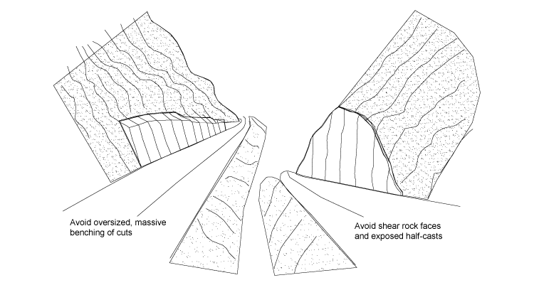
Figure 2. Illustration. Details of typical slope cuts to be avoided.
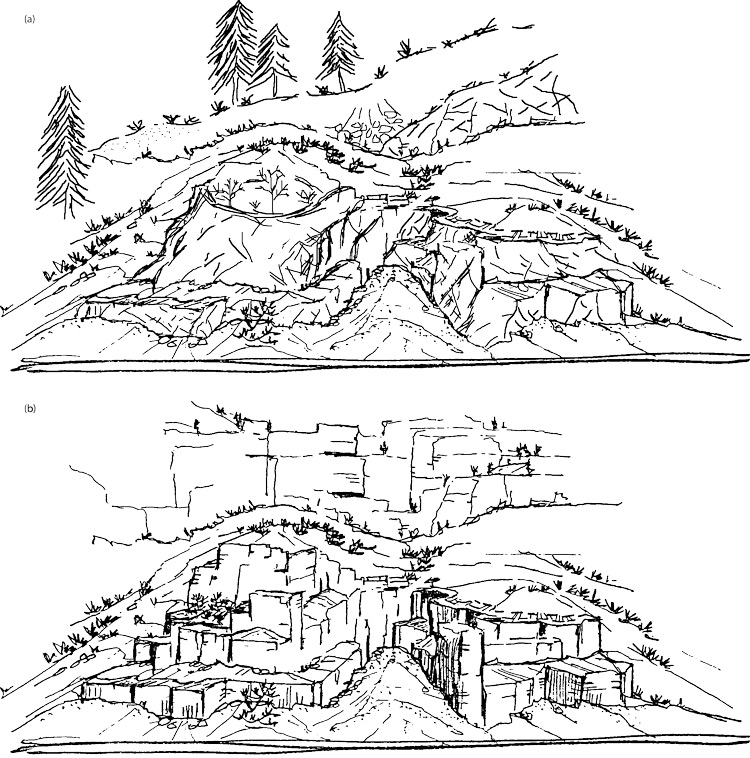
Figure 3. Illustration. Perspective view of the desired slope configuration and key design elements for different geographic settings. (a) Alpine environment with slope rounding and talus deposits (b) Arid/desert environment with blocky slope transitions and sparse vegetation.
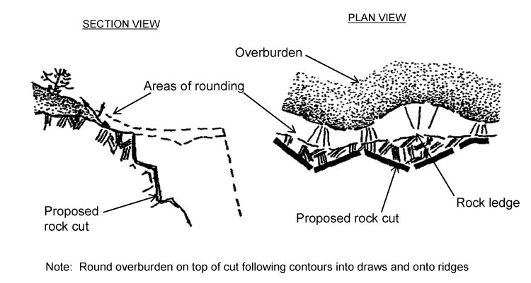
Figure 4. Illustration. Example of typical details for a sculpted rock cut.
Figure 5. Illustration. Slope variation details used to enhance aesthetics.
Stay up to date
Sign up for announcements on grant opportunities, training, and webinars.