Previous Chapter « Table of Contents » Next Chapter
This section reviews standard excavation practices used to construct and modify rock slopes and provides current design and construction guidelines for their use in context sensitive areas. Several of these practices have been used for many years, while others are new techniques or recent modifications of established methods. The most common are blasting (which includes drilling the holes to be filled with explosives), ripping, and breaking. Table 1 provides a brief description of these procedures, along with the advantages and limitations of each. Each procedure is discussed in detail below.
Blasting-the controlled use of explosives to excavate rock-has been part of construction engineering for hundreds of years.
In any blasting situation, the geologic structure of the rock mass will be the most important consideration. Other considerations include the degree of scarring that would be acceptable (some areas can tolerate more blasting scars than others), cost, and safety (blasting cannot be performed in close proximity to populated areas).
The first consideration when designing a blasting operation should be the local geologic conditions. Rock competency and fracture patterns can have a significant impact on the success of a blasting operation.
When discussing blasting, the single most important geologic factor is fracture: the spacing and orientation of any breaks, or discontinuity sets, in the rock. In particular, the orientation of the discontinuity sets with respect to the cut slope angle will influence any slope failures that may occur along the slope face. The modes of failure can be grouped into four primary mechanisms, shown left to right in Figure 6.
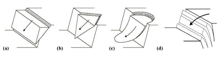
Figure 6. Illustration. The four primary mechanisms of slope failure.
Table 1. Description, advantages, and limitations of common excavation practices.
| Procedure | Description | Advantages | Limitations |
|---|---|---|---|
| Presplit Blasting | Presplit holes are blasted before production blasts. Procedure uses small diameter holes at close spacing and lightly loaded with distributed charges. | Protects the final cut by producing a fracture plane along the final slope face that fractures from production blasts cannot pass. Can produce steeper cuts with less maintenance issues. Performs well in hard competent rock. | The small diameter borings limit the blasting depth to 15 m (50 ft). Borehole traces are present for entire length of boring. Does not perform well in highly fractured, weak rock. |
| Smooth Blasting | Smooth blast holes are blasted after production blasts. Procedure uses small diameter holes at close spacing and lightly loaded with distributed charges. | Produces a cosmetically appealing, stable perimeter. Can be done on slopes years after initial construction. Drill hole traces are less apparent than presplitting. Performs best is hard, competent rock. | The small boring diameter limits blasting depth to 15 m (50 ft). Borehole traces are present for much of the boring length. Does not protect the slope from damage caused by production blasting. Does not perform well in highly fractured, weak rock. |
| Cushion Blasting | Cushion blasting is done after production blasts. Larger drill holes are used with small diameter, lightly loaded distributed loads. Space around the explosive is filled with crushed rock to cushion the explosive force. | Reduces the amount of radial fracturing around the borehole and also reduces borehole traces. The large diameter holes allow blasting depths up to 30 m (100 ft). Produces a ragged final slope face. Performs well in all rock types. | Radial fractures are more abundant than presplit and smooth blasting. Slope face is more prone to raveling. A catchment area is recommended at slope base. More demanding on the driller. Borehole traces still apparent in hard, competent rock. |
| Step Drilling | Larger diameter drill holes, drilled vertically and used as production blasting (although spaced closer and loaded lighter to minimize radial fractures). Slope face is formed along base of blast holes. | If properly designed the final slope face shows minimal signs of blasting. Can be used when sloped controlled blasting cannot. Best used in moderately to highly fractured rock. | Can produce extensive damage to slope or inadequate base fracturing if not designed properly. Should only be used with experienced driller and blasting engineer. Only applicable for slopes between 0.7:1 and 1:1 (H:V). Does not perform well in hard competent rock. |
| Horizontal Drilling | Larger diameter, closely spaced, lightly loaded horizontal borings are used for production style blasting. Used in massive rock to eliminate drill holes or in areas of poor access. | Eliminates bore hole traces when drilled perpendicular to the slope face. Good in massive rock where traces are not acceptable. | Demanding on the driller and explosives engineer. Can produce extensive radial fractures or inadequate base fracturing if not loaded properly. Requires complicated loading and timing procedures, and special stemming procedures. |
| Ripping | Uses a tractor with an attached tooth or teeth that is lowered into the rock and dragged to break up material for excavation. | Much cheaper and safer than blasting. Can be done in close proximity to development without disturbance. Is effective on a variety of angled cuts and an excavator can be used after ripping to slope sculpting. | The tooth of the ripper can leave scars on the rock surface. The tractor cannot be used on steep slopes because of risk of overturning. Ripping is limited to relatively low density rocks. |
In order to avoid long-term slope instability and increased maintenance costs, designers should measure and evaluate prominent discontinuities on the rock face using a scan line survey and computer-based kinematic analysis, also known as a equal area net (or stereonet) analysis. Regardless of the number of joints in a slope, one set will usually be the dominant (or weakest) and therefore will dictate the rock slope design. Generally speaking, the direction of this dominant joint will have the greatest influence on blasting results and potential failure modes. For example, if this joint set is parallel to the final slope face as illustrated in Figure 7, the borehole can prematurely link to the joint, which will create coarse or blocky burden fragmentation and severe end break (breakage at the end of the row of blastholes). In this case, increasing the borehole spacing will reduce fragmentation size (if the end result of the blast will be rip-rap, the explosive load can also be reduced).
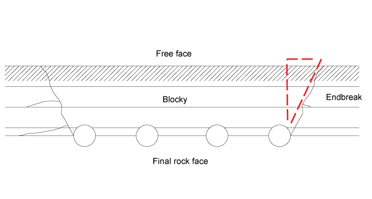
Figure 7. Illustration. Excessive end break caused by blasting parallel to jointing (modified from Konya and Walter 2003).
However, there can be problems blasting perpendicular to the final slope face, as well illustrated in Figure 8. While end break is not typically a problem in this case, backbreak (or overbreak)- fractures that extend from the blastholes back into the final slope face-can be significant (backbreak can cause slope instability and possible raveling of large blocks during excavation and thereafter). In addition, creating blastholes in an area with a significant number of joints can create blocky breakage. Reducing the spacing between blastholes can prevent this, but it might make backbreak worse. In this case, using smaller blastholes with a better distribution of powder may be the best solution (Konya and Walter 2003).
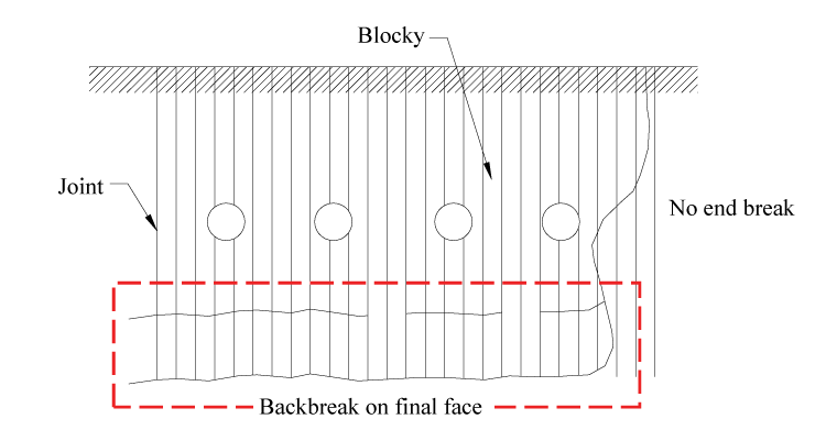
Figure 8. Illustration. Excessive backbreak caused by blasting perpendicular to jointing (modified from Konya and Walter 2003).
When blasting perpendicular to the final slope face, discontinuities occurring at sharp angles from the excavation plane tend to have the biggest effect. For example, discontinuities between 30° and 80° don't have much impact, but discontinuities from 20° to 25° can create some backbreak. Discontinuity angles less than 15° can allow the blast energy to travel into the discontinuity plane, which can cause it to form the final slope face as shown in Figure 9.
However, if these discontinuity planes are favorably orientated with respect to the road (orientations that parallel the road alignment or road bed), they can be used for the final face of the cut slope, resulting in a more natural-looking rock cut. The use of favorable joint orientation and/or bedding planes for controlling the blast is the most common and accepted method for developing rock slopes that fit within the geologic context of the surrounding area.
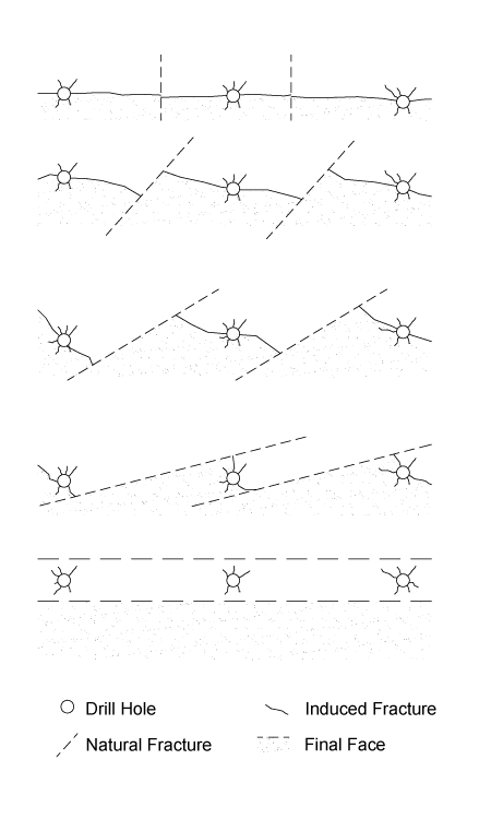
Figure 9. Illustration. The effect of joint orientation on the quality of the final wall face (modified from Matheson 1986).
A slope's dip-its fall, illustrated as an imaginary line running down the steepest part of the slope-is another important factor to be considered in blasting. Blasting with the dip carries a greater risk of backbreak than blasting against the dip because the discontinuities (joints, bedding, etc.) channel the energy along the planes. However, this type of blasting allows engineers to use smaller explosive charges (or blast larger burdens) because the blasted rock moves more readily down the slope than it would if the blast were oriented against the dip. Blasting with the dip also creates a better-looking slope toe.
On the other hand, blasting against the dip typically creates less backbreak but can create more overhangs. It also can leave more material at the slope toe, resulting in a rough surface. Blasting against the dip also removes a smaller burden, meaning it will require more explosives.
Figure 10 illustrates the effect of dip on blasting. In this cut, blasting on the left side was performed against the dip, while blasting on the right side was done with the dip.
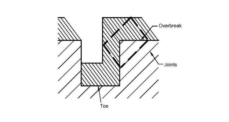
Figure 10. Illustration. Example of an excavation that blasts against the dip on the left side and with the dip on the right side (modified from Konya and Walter 2003).
The strike of a slope-the direction the crest of the slope travels (i.e., the "across slope" direction), also plays a role in blasting design. Blasting parallel to strike in bedded rock can produce unpredictable results. The blast pattern intersects many different rock layers, and each layer will respond differently, as fragmented block size, toe conditions, and degree of backbreak all may vary slightly among them as shown in Figure 11.
In addition to strike and dip, the presence of mud or soft seams in a slope also requires special consideration in the blast design. They can occur in any rock type, and are often unseen. Clay seams often respond like a liquid in that during initiation of a blast they provide an almost instantaneous attenuation of explosive energy. Therefore, it is essential to stem across soft seams to obtain good blasting results.
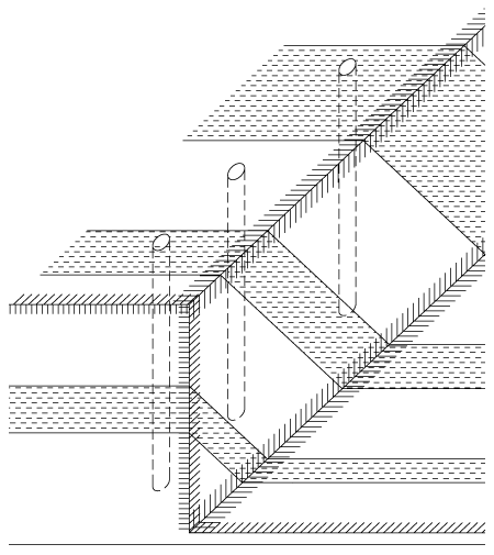
Figure 11. Illustration. Example of a blasting pattern that runs parallel to strike (modified from Konya and Walter 2003).
Stay up to date
Sign up for announcements on grant opportunities, training, and webinars.