Previous Chapter « Table of Contents » Next Chapter
Most reinforcement systems work to strengthen the rock mass internally by increasing its resistance to shear stress and sliding along fractures. Other systems work externally to protect the rock from weathering and erosion and to add a small amount of structural support. An example of this is shotcrete (concrete or mortar that's "shot" onto the rock).
Internal stabilization is accomplished by tensioned and untensioned rock anchors, injectable resin, and drainage.
The most common type of internal reinforcement are anchors, which are threaded steel bars or cables that are inserted into the rock via drilled holes and bonded to the rock mass by cement grout or epoxy resins. (Friction bolts are considered temporary measures and typically are not used in the transportation industry.) Because the bond strength between the cement grout or resin and the rock is less than the maximum yielding stress of the steel, it has a large impact on the design load of the rock reinforcement.
Rock anchors can be used to secure a single loosened block or to stabilize an entire rock slope that is affected by a prevalent rock structure. Bolt and cable lengths are highly variable and are compatible with a variety of rock types, structural characteristics, and strengths. Anchors can be combined with other stabilization techniques if they cannot mitigate the hazard alone. Disadvantages include relatively high cost, susceptibility to corrosion, and lengthy installation times, which can slow the construction of the rock slope.
The anchors used for slope stabilization are typically 6 m (20 ft) in length, 20 mm to 50 mm (5/8 to 2 in) in diameter and made of high-strength steel (bars can be coupled to increase the length up to 30 m or 100 ft, but the total length of a stabilization bar is generally limited to 12 m or 40 ft). Rock anchors can be tensioned or untensioned.
Tensioned Anchors (Rock Bolts):
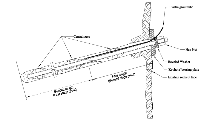
Tensioned anchors (also known as rock bolts) are used on rock masses that already show signs of instability or on newly cut rock slopes to prevent movement along fractures and subsequent decrease of shearing resistance. A hex nut and bearing plate are used to distribute the tensile load from the bolt to the rock mass as illustrated in Figure 41.
Rock bolts are considered a type of active reinforcement due to the post-tensioning they provide, and are used to add compressive stress to joints within a rock mass. This force increases the friction along the fracture planes and helps to reduce block movement.
Tensioned rock bolts can require more time to install than dowels because installation involves several steps: drilling, grouting the bond length and inserting the bar or cable, then tensioning the anchor and grouting the free length. Because the tension in the bolt can reduce over time due to creep and become "seized" by small shears in the rock mass, rock bolts may need periodic re- tensioning.
Untensioned Anchors:
There are two types of untensioned anchors used in rock stabilization: rock dowels and shear pins. Both are untensioned, fully grouted steel bars used for passive reinforcement. Dowels are used on steep slopes in the same fashion as rock bolts, while shear pins are used on flatter slopes where bedding planes and discontinuities determine the slope angle and failure plane.
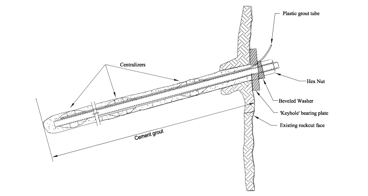
Rock dowels as illustrated in Figure 42, are typically used on newly excavated slopes. They can be installed in a grid pattern to support an entire face or used to support one block. They provide initial reinforcement through the shear strength of the steel, which increases friction along the potential plane of weakness. Once block movement occurs, depending on dowel orientation, the tensile strength of the bar is engaged and the normal force between opposing discontinuities is increased.
Dowels can be used in highly fractured and weak rocks that cannot hold a tensioned rock bolt. They also can create a more natural-looking slope face, as the plates can be removed in massive rock formations without close jointing that would inhibit the face support contribution of the dowel. The boreholes can be covered with grout that's been colored to match the surrounding rock. Because dowels are installed in one step, they are quicker to install than tensioned bolts.
Rock Anchor Design and Installation:
Rock reinforcement design relies primarily on surface mapping and logging discontinuities from borehole data to assess fracture/joint patterns and other conditions, as discontinuities strongly control rock slope stability. Surface mapping is usually conducted as window mapping or scan- line mapping. In some cases, engineers should also obtain test hole data, especially if surface mapping is not feasible due to the presence of overburden soil or for other reasons. As is true in any slope assessment, it is also important to assess the groundwater present in the rock discontinuities to measure slope stability.
To determine the slope's safety, the following conditions should be evaluated: the height and thickness of the rock mass that requires stabilization, and the shear strength of the failure plane (determined by the friction and cohesion of the plane, as well as groundwater conditions, rock type, and other geologic features). Figure 43 depicts a rock slope stability analysis diagram assuming a tension crack in the slope face for a planar slope failure.
The reinforcement load is applied in the stability analysis either as a single stabilizing element or a series of reinforcing elements to achieve the desired factor of safety. The length of the bolt or cable is dependent on the bond strength (adhesion to the rock) and the discontinuity spacing that forms the deepest part of the block. Tendon lengths can range from 2 to 30 m (6 to 100 ft); however, in the transportation industry, the tendon length rarely exceeds 10 m (30 ft). The detailed requirements for site investigation and analysis of rock cuts are provided in FHWA HI- 99-007 Rock Slopes Reference Manual (Munfakh, Wyllie, and Mah 1998)
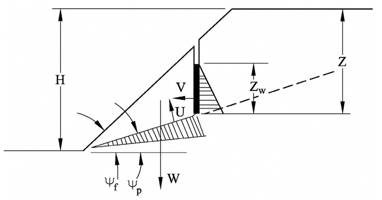
Where:
Rock anchors are usually installed in a grid pattern, where each anchor is the same length and set at a predetermined distance from the surrounding bolts. Following a set pattern can improve the structural stability of an entire rock face, especially for weathered or highly fractured rock. On competent rock masses with large block sizes, engineers typically identify "key blocks" (i.e., blocks of rock that control support for surrounding blocks), then design a bolting pattern around them that makes it more difficult for the surrounding blocks to move. Designing a key block pattern requires engineers to map the three-dimensional fracture orientations, but can decrease the number of rock bolts required to stabilize a slope.
In both tensioned and untensioned anchors, the bearing plate and hex nut are used to distribute the load of the anchor to the rock face; a beveled washer is used to apply the load evenly when the bolt is angled in relation to the rock face. In rock masses with few discontinuities, the plate can be removed and the tendon (bar or cable) cut to allow for the installation of a grout cover or plug. This method is highly contingent on the quality of rock and stability of the rock mass.
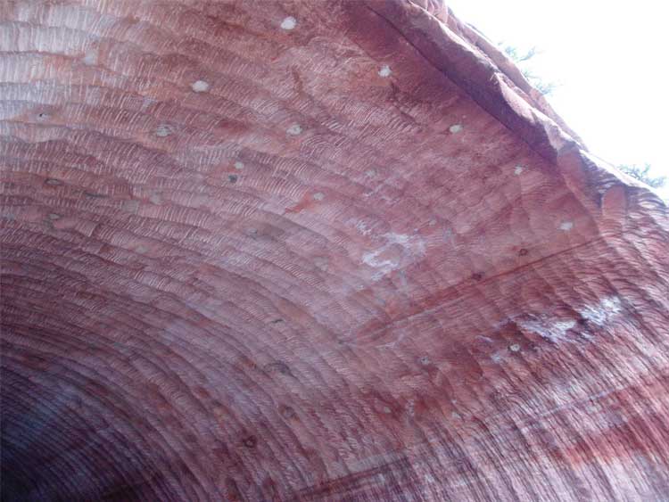
In the tunnel shown in Figure 44, dowels were used to support a tunnel crest; the visible ends were covered with a colored grout to help mask their presence. Only the grout at the end of the tunnel is visible because the surrounding rock is darker and provides more contrast with the lighter-colored grout than the rock in the center of the tunnel.
Design analysis determines the depth of the boreholes required for rock bolts and dowels. The reinforcing element is grouted into place using either cement- or epoxy resin-based grout. Both bonding agents use either a one- or two-step application process, depending on the type of anchor being used.
Grouting for rock bolts is typically applied in two steps. In the first step, the grout or resin is injected into the base of the borehole-the section known as the "bond length" of the bolt-and allowed to set. After the bond length is dry, the bearing plate and hex nut are installed, the bolt is tightened, and the remaining length (the "free length") is filled with grout or resin. In some cases, contractors can accomplish the grouting in a single step, by using two types of grout or resin, each with a different set time. In this method, the bond length is filled with a quick-set product while the remainder of the hole is filled with a slow-set product; the quick-set resin is allowed to harden, then the bolt is tightened before the slow-set resin sets.
Shear pins and dowels can be grouted in one stage, using cement grout or a single resin.
When installing rock anchors, contractors often use polyester resin because of its ease of application and adjustable set times. It comes in a two-part package that is inserted into the borehole before the bolt. The bolt is inserted into the borehole and rotated in place to break up and mix the resin. (The two-part resin cannot be used with cable tendons, which are flexible and therefore do not effectively break up and mix the resin.) Polyester resin is generally used in short-term or temporary applications. Cement grouts are slower to set, but form a reducing environment that makes them better suited for corrosive environments and permanent applications.
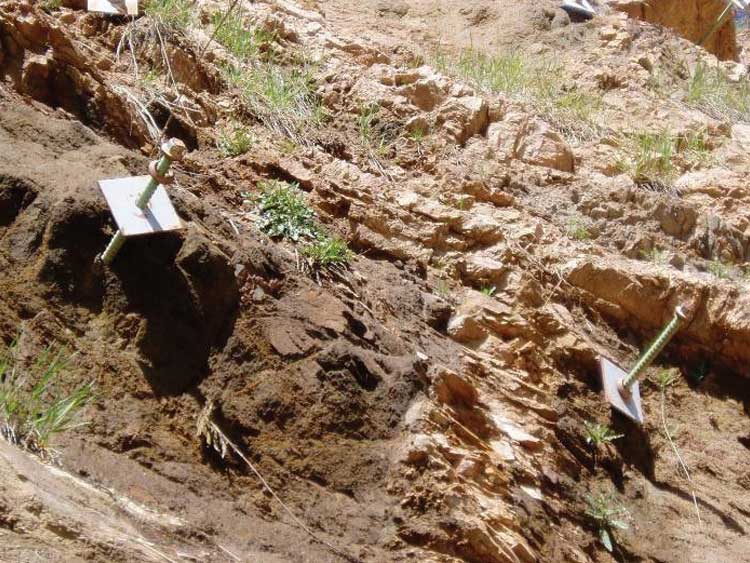
The final location of the rock reinforcement is determined in the field during construction. It is imperative that the reinforcement is correctly located on a rock surface that is not prone to weathering, as erosion around the bearing plate can cause a loss of tension. Figure 45 shows bolts that have failed because of erosion of the surrounding rock.
Installing bolts, dowels, and shear pins most often requires a hand-held or mounted rock drill (normally percussion style), reinforcing tendon (rod or tensionable cable), hex nuts, washers and bearing plates, either epoxy or cement grout for adhesion, and a hydraulic jack or torque wrench.
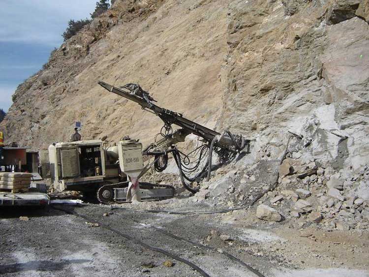
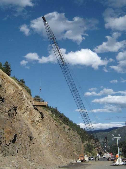
Figure 46 illustrates the typical track drilling equipment used to install rock reinforcement. In areas where access is difficult, a man lift or crane may be needed as shown in Figure 47.
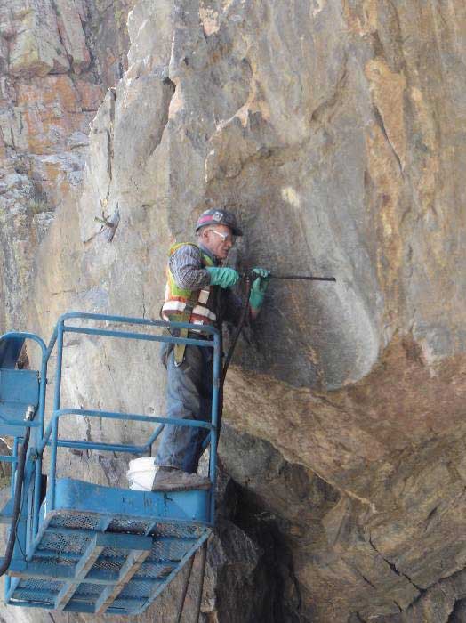
In the mining industry, injectable resin and epoxy have been used since the 1960s to stabilize underground coalmines. Since then, they have also been used on numerous geotechnical and geological engineering projects. When injected into a rock mass via drilled boreholes as shown in Figure 48, these materials follow any fractures and discontinuities around the holes, thus increasing the rock's stability. Rock masses that are excessively fractured and/or contain voids will require large amounts of filler, which can result in excessive cost overruns (for proper resin/grout movement and to keep pumping pressures at a minimum, the discontinuity aperture spacing should be at least 2 mm, or 1/16 in.).
In suitable slopes, injecting resin or epoxy is very effective in providing additional slope stability without negatively effecting aesthetics. There is virtually no maintenance required after resin/epoxy injection. And while research on the application and effectiveness for the use of injectable resin/epoxy as the primary means of slope stabilization is ongoing, initial findings indicate that it can reduce the number of rock bolts needed for slope stabilization.
The first step in installing resin/epoxy is to choose the proper product to use in the rock mass. The primary factor for determining this is the presence of water in the fractures. Products are characterized as either hydrophilic or hydrophobic.
Hydrophilic products, such as polyurethane resin (PUR) and polyurethane (PU), incorporate water into their chemical structure and will shrink (or swell) depending on the amount of water present. Typically, hydrophilic products will swell between 25% and 3,000% and/or elongate 10% to 500%, depending on the presence of water and available space for expansion (Arndt, DeMarco, and Andrew 2008). On the flip side, the product can shrink more than 10% in the absence of water, and can also become dry and crack. Typically, hydrophilic products are used as a water barrier or sealant. They perform best when in continuous contact with water. The shear strength of hydrophilic products is significantly less than the more dense hydrophobic products, but they permeate into moist or water-filled fractures and voids without requiring significantly more pumping pressure, as hydrophobic products do.
Hydrophobic products, such as epoxy grouts (EP), react less with water and therefore expand and contract considerably less than hydrophilic products. This results in a denser final product with greater shear strength. Hydrophobic products will not permeate as well into water and require higher pumping pressures when pumped into water-filled discontinuities because they need to overcome the hydraulic head to displace the water. A comparison between PU, PUR, and EP products is shown in Table 9.
Table 9. Properties of different rock-bonding products (Arndt, DeMarco, and Andrew 2008).
| Property | Polyurethane (PU) | Polyurethane Resin (PUR) | Epoxy (EP) |
|---|---|---|---|
| Component Mixing |
One-Stage | Two Stage | Two-Stage |
| Injection Type |
Foam/Gels/Grout | Grout | Grout |
| Injection Pressures |
Low to High 700 to 21,000 kPa (100 to 3,000 psi) |
Low to High 70 to 21,000 kPa (10 to 3,000 psi) |
Low to Medium 200 to 5,500 kPa (30 to 800 psi) |
| Density |
Low to Medium 50 to 800 kg/m3 (3 to 50 pcf) |
Medium to High 320 to 1,100 kg/m3 (20 to 70 pcf) |
Low to High 80 to 960 kg/m3 (5 to 60 pcf) |
| Compressive/Tensile Strength |
Low 70 to 3,500 kPa (10 to 500 psi) |
Low to High 100 to 140,000 kPa (15 to 20,000 psi) |
Medium to High 34,000 to 140,000 kPa (5,000 to 20,000 psi) |
| Viscosity |
Low to Medium | Low to High | Very Low to High |
| Water Interactions |
Hydrophilic | Hydrophilic/Hydrophobic | Hydrophobic |
| Expansion/Elongation |
Varies (10% to 3,000%) |
Varies (10% to 3,000%) |
Minimal |
| Shrinkage |
Varies (1% to 10%) |
Varies (0% to 3%) |
Minimal |
| Relative Product Cost |
Low | Mid to High | High |
Estimating the pre-injection volume of resin/epoxy can be difficult because it is dependent on the moisture and interconnectivity of the fractures. Generally speaking, dry to slightly moist fractures will require about twice the amount of product being injected per hole compared to very moist to wet fractures.
Boreholes should be spaced approximately 2.5 to 5 m (8 to 16 ft) apart. Holes can be drilled ahead of time or right before injection. In cases where the migration distance of the product is unknown, drilling holes too close together can cause the resin/epoxy to extrude from adjacent holes, while drilling the holes too far apart can result inadequate product distribution. The placement and orientation of the injection boreholes should intersect as many fractures as possible. Ideally, the boreholes should intersect the major discontinuities at a 90° angle and/or at the intersection of fractures to maximize the injection potential of the product.
If possible, construction should take place during the region's dry season so that fractures will contain minimal moisture. Injection should proceed from the bottom of the slope to the top. To ensure proper distribution of product around the borehole, the contractor should proceed until overrun is observed, then end pumping for approximately one minute to allow the product to start to set. The contractor should then resume pumping to push the new volume of product into other fractures and joint sets and continue this staged pumping procedure until overrun is seen above the injection site. Pumping pressures need to be closely monitored and kept at a minimum to prevent movement within the rock mass and/or the displacement of any rocks. Evidence shows that pressures more than 1,800 kPa (250 psi) can cause problems, even though the material specifications have ranges with upper ends exceeding this value. It is best to remove overrun product immediately, before it becomes hard (at this stage, it easily peels from the rock face). After the product dries, it will have to be chipped away.
Equipment required includes a man lift, shown earlier in Figure 48, capable of reaching the slope crest, plus a percussion-type drill, either hand operated or attached to the lift, an air compressor to operate the drill, a resin/epoxy pumping and mixing system, and an injection port with a diameter slightly smaller than the borehole diameter.
Polyurethane Resin (PUR) was used recently on a mountain highway in Poudre Canyon, Colorado, to stabilize 80 m2 (850 ft2) of a rockfall-prone slope adjacent to a tunnel portal. The geology consisted of gneiss with fracture sets spaced between 0.5 and 3 m (1.5 to 9 ft) apart with dry to slightly moist apertures with openings greater than 2 mm (1/8 in).
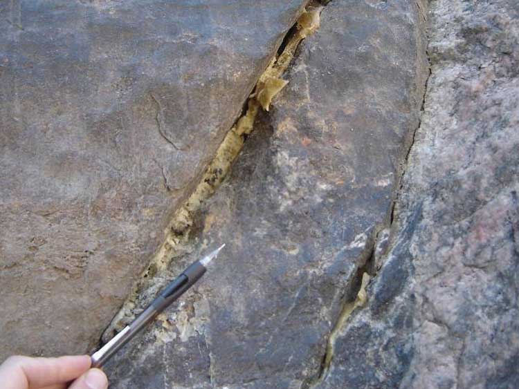
Sixteen holes, 38 mm (1.5 in) in diameter, were drilled between 3 to 3.5 m (10 to 12 ft) deep. Between 90 to 315 kg (200 to 700 lb) of PUR was injected into each hole, for a total of more than 2,250 kg (5,000 lb) of product. As shown in Figure 49, PUR was seen extruding out of the surface fractures more than 1.5 m (5 ft) from the injection point. Injection times ranged from 20 to 40 minutes. No rockfall was encountered during the drilling or injection process, and there is no visible evidence that any work has been done at the site.
Stay up to date
Sign up for announcements on grant opportunities, training, and webinars.