Previous Chapter « Table of Contents » Next Chapter
Shotcrete is a wet- or dry-mix mortar with a fine aggregate (up to 23 mm, or 7/8 in) that is sprayed directly onto a slope using compressed air. Several applications may be needed to build the shotcrete up to the required thickness. Unreinforced shotcrete gives little structural support or protection against weathering, but can be used to prevent differential erosion between units, slope raveling, and loosening of blocks. Shotcrete can also be applied around the exposed ends of rock bolts to help prevent weathering around the bearing plates and limit slope degradation.
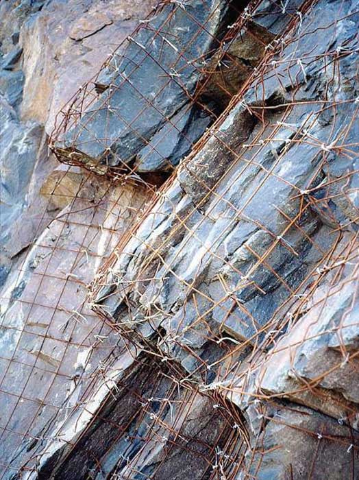
To increase tensile strength and structural support, the contractor can include fibers in the shotcrete mix or apply the shotcrete to welded wire mesh shown by Figure 50.
Shotcrete can vary in appearance from very rough-in its natural, "as-shot" (unfinished) condition-to moderately rough in the "rodded" condition, to as smooth as cast-in-place concrete (with appropriate finishing). Architectural shotcrete (known as façade or sculpted shotcrete) can produce a wide range of finished surfaces.
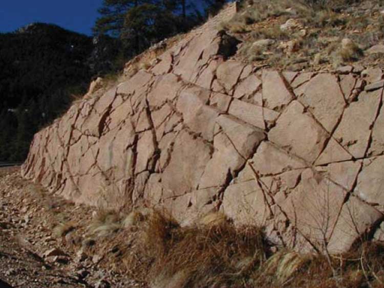
In contrast to cast-in-place concrete, shotcrete can be shaped, contoured, and colored to match the surrounding rock as shown in Figure 51.
In most instances, structural shotcrete is applied to rock slopes to protect a surface which, left untreated, would erode (such as a fault zone or clay seam), or to provide structural support for otherwise sound rock that is either undermined by erosion or is unstable due to unfavorable orientations or degree of fracturing. This type of shotcrete application can be part of the original construction or part of the remediation of an existing unstable rock slope.
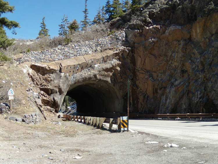
Structural shotcrete can also be used to form part of a retaining system supporting the rock slope as shown in Figure 52. The system typically includes other components such as welded wire mesh, rock bolts, and/or dowels (the shotcrete also may be fiber-reinforced to improve its tensile capacity). In these applications, the shotcrete will be required to resist or transfer loads and may also have an essential surface protection function in conjunction with its structural function.
Unreinforced shotcrete can be used to cover a well-defined strip (or strips) of rock with a higher rate of erosion than the surrounding rock (faults or shale lenses in sandstone, for example) or an entire slope composed of highly erodible material. In the latter case, the designer should consider laying the slope back to avoid a structured solution, as differential erosion of the rock slope will create stability problems that become worse with time.
A façade of sculpted (or architectural) shotcrete can be used to improve the appearance of structural shotcrete as well as an engineered slope.
In any shotcrete application, drainage (in the form of weep holes or wick drains) will be required to draw water from behind the shotcrete to prevent elevated water pressure from causing cracking and instability in both the shotcrete and localized blocks.
Color can be applied to the shotcrete surface to help it blend with its surroundings. To achieve the best results, the designer and contractor should consider the following:
The texture of the shotcrete is almost as important as color, but it is often overlooked in shotcrete applications. Most natural rock is characterized by a collection of planar surfaces, while shotcrete has a granular, amorphous finish. Designers can apply a variety of textures to shotcrete, such as these:
Before shotcrete application, the rock face should be scaled and cleaned to remove any loose material (rock, dirt, ice, vegetation, etc.) that may hinder bonding. Highly fractured or weak rock should be removed to expose more competent material (if the shotcrete is incorporated with welded wire mesh and rock bolts/dowels, this is not necessary). In any case, the face should be free of flowing water but damp enough to facilitate proper curing. Any wire mesh should be attached securely to the area of application, as it will act as a frame to hold the shotcrete in place.
As mentioned earlier, shotcrete comes in both wet and dry applications. The wet application is mixed with water before it enters the application nozzle, while dry applications are mixed with the water at the nozzle. Air entertainment is not possible with dry mixes, so resistance to climatic freeze/thaw can be reduced.
Applied shotcrete varies in thickness, from 50 mm to 0.6 m (2 in to 2 ft). For thicker applications, shotcrete should be applied in multiple layers of about 50 to 100 mm (2 to 4 in) each and allowed to cure between applications. Installing shotcrete requires an air compressor, application nozzle, and cement mixer. The application nozzle is either hand held or attached to a man lift or crane. Reinforcing the shotcrete with welded wire mesh or fibers can greatly increase its tensile strength, stand-up time, and rock-bonding potential, as well as the overall stability of the rock mass.
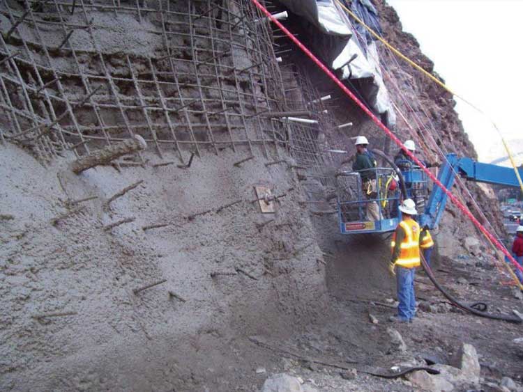
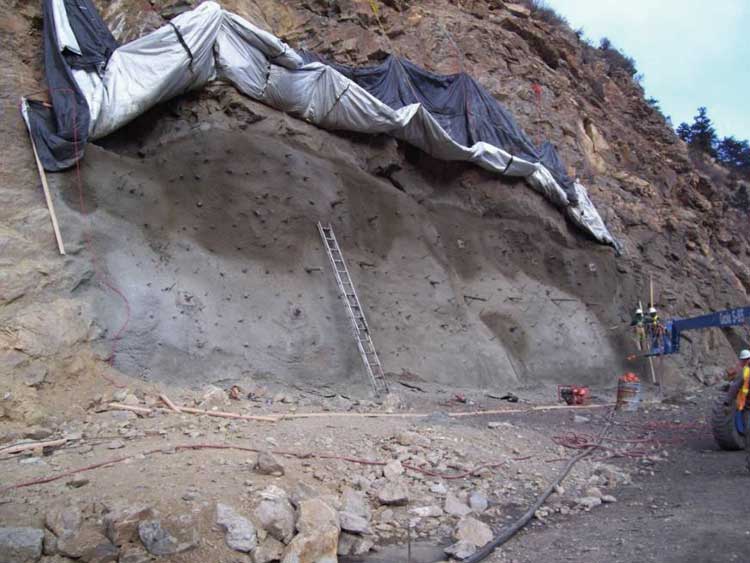
Figure 54 shows the installation near completion of the first layer of shotcrete on the slope, which took three days to achieve. It is necessary for each layer to dry and gain enough strength for the application of the subsequent layer.
After installation of the structural shotcrete is completed, the sculpted shotcrete façade is installed. In Figure 55, the contractor has installed a grid of rebar and pockets of welded wire mesh to help form and suspend the façade.
Figure 56 shows the finished sculpted shotcrete façade prior to the application of stain.
Slope stability can also be improved through the installation of drainage systems, which most often consist of horizontal weep drains.
Water in a rock slope often contributes to slope instability, as excessive pore pressure acts on the rock mass and lowers the shear strength along any discontinuities. Water also contributes to rock degradation and fracture expansion and during the process of freeze-thaw weathering.
Normally, drainage systems are used in weak, highly fractured, or layered rock where instabilities could occur along a potential sliding surface. Drainage is generally used to mitigate larger rockslides and failures. In most cases, the drains are installed as uncased holes in massive rock units, drilled with a track rig or portable drill. In weak or highly fractured rock, the drain may be cased with a slotted polyvinylchloride (PVC) pipe to maintain the drain opening. Drains are installed at the base of the slope, and require periodic maintenance to prevent clogging. Usually, they are used in conjunction with other stabilization measures.
Horizontal drains can be installed in a rock slope to reduce pore pressure and improve stability, and are a cost-effective, aesthetically pleasing, and relatively low-maintenance option for most slopes with excessive flowing water. They are most effective for large-scale slope instability, where the potential sliding planes are deeply seated within the rock mass.
The most important factor in designing horizontal drains is to orient the holes so they intersect the maximum number of water-carrying fractures, as very little water is contained within the intact rock. Drainage holes should be spaced about 3 to 10 m (10 to 33 ft) apart and drilled to a depth of at least one-third of the slope height. Once the water is drained from the slope, it must be diverted away from the slope base to prevent infiltration, which could create additional stability issues. In addition, the slope base must be protected from motorists and any obstructions that could damage the drains or inhibit water movement.
Piezometers installed in the slope can monitor the water pressure and the effectiveness of the installed drainage, allowing engineers to determine if the drainage is sufficient or if additional drains are needed.
Horizontal drains are constructed used conventional rock drilling equipment. The hole location, orientation, and angle are determined based on the fracture patterns in the rock. The installer may need to adjust the assumed orientation and angle based on water conditions encountered. Normally, drainage holes in rock can be drilled using a track rig or hand-held drill (hand-held drills are limited to relatively shallow drainage holes). In highly fractured or weak rock, the hole should be cased with a perforated PVC pipe to prevent collapse. Perforation size should limit the amount of fine particles that infiltrate into the pipe. Surface drainage produced from slope de- watering can be diverted or contained using a lined gutter, culvert, or collection system.
Stay up to date
Sign up for announcements on grant opportunities, training, and webinars.