Previous Chapter « Table of Contents » Next Chapter
Structures designed to protect the areas around a slope from falling rocks include mesh or cable nets, barriers and fences, and catchment areas (ditches at the toe of a slope, designed to prevent rockfall from reaching the highway). These devices allow rocks to fall but prevent them from causing any damage to a structure or the public. The protection can stop a rock, control its trajectory, reduce its energy, and/or provide a catchment. In many cases, a catchment is used in conjunction with an inclined deceleration zone.
However, because they are external to the slope, these structures are typically more difficult to hide-or to fit within the context of the surroundings-than structures that are integrated into the slope.
Another option for protecting against rockfall is the use of avoidance measures, such building a tunnel, realigning the roadway, or constructing an elevated portion or portions, which ensure that the road will be out of the path of any foreseeable rockfall.
Because of the significant amount of information on protective methods and design available today, only a brief overview of the most frequently used methods will be covered here. Table 10 provides an overview of the most common protective measures used in the transportation industry.
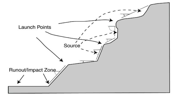
To develop effective rockfall protection, the engineer should evaluate the slope through a thorough site investigation. Factors affecting rockfall that must be considered include slope height, topographic profile, variable slope angles, potential launch points, rock type variations, soil cover, vegetative cover, potential runout areas, and impact zones.
A cross section and contour map that identifies geometric characteristics of the slope should be developed. The cross section should begin at the source area (the origin of the falling rock) and end past the runout zone as illustrated in Figure 57. This will help establish the rockfall height as well as its potential energy. Significant features such as slope angle changes, launch points, ridges, and gullies largely define the path of travel by channeling, launching, and/or hindering the falling rock. They also affect the rockfall's mode of travel: rolling, bouncing, or free falling. Existing impact locations on structures, trees, or other impediments allow the engineer to make rudimentary estimates of bounce heights and launch points. Slope height and angle play a major role in the amount of energy that is carried by the falling rock, but they are not the only factors to consider.
Table 10. An overview of rockfall protection measures and their limitations.
| Protection Measure | Description/purpose | Limitations |
|---|---|---|
| Mesh/cable Nets | ||
| Draped Mesh/Nets |
Hexagonal wire mesh, cable nets, or high-tensile- strength steel mesh draped over a slope face to slow erosion, control the descent of falling rocks, and restrict them to the catchment area. | Require a debris-collection catchment area. Must consider debris and snow loads on anchors.
Typically limited
to areas with rocks smaller than 1.5 m (5 ft) in diameter. Visible to passing motorists. |
| Anchored Mesh/Nets |
Free-draining, pinned/anchored-in-place nets or mesh. Used to apply active retention force to retain rocks and soil on a slope. |
May form pockets of accumulated rock. Can be difficult to clean out. Can be visible to passing motorists. |
| Barriers | ||
| Earthen Barriers | Barriers constructed of natural soil and rocks (berms) or mechanically stabilized earth (MSE), placed at the distal end of a catchment area to improve its effectiveness. MSE walls, in particular, can withstand large kinetic energies and repeated impacts. Easily repaired. Earthen material blends well with surrounding landscape. | Catchment area must be periodically cleaned to remove accumulated material. Berms of considerable height require a wide base area. |
| Concrete Barriers | Rigid barriers that provide protection from low- energy impacts. Relatively cheap, easy to obtain,
and fast to
install. Normally used as temporary barrier in context sensitive areas. |
High stiffness causes barriers to crack and/or shatter in high-energy impact. Not visually appealing. |
| Structural Walls | Rigid barriers used to intercept falling rocks and restrict them to a prescribed catchment area. Can
withstand
significant kinetic energies and repeated impacts. Facing can be installed on road side of walls to improve aesthetics. |
Catchment area must be periodically cleaned to remove accumulated material. Prone to damage by high-energy events |
| Flexible Barriers | Flexible barriers made of wire ring or high- strength wire mesh with high energy-absorption
capacity,
supported by steel posts and anchor ropes with a braking system. Fence is fixed at the bottom to hold
rocks.
Effective on high- to low- energy events. |
Require room for rocks deflected by barriers during impacts. Must be cleaned out periodically.
Fairly
expensive to construct and prone to damage by higher- energy events. Do not blend well into surrounding landscape. |
| Attenuators | Flexible barriers similar to fencing (above) but not attached at bottom (an extra length of fence
lies on the
slope face); allow rocks to move beneath the two sections of fence and direct them into a catchment
area.
Require less maintenance than standard fencing. |
Visible to passing motorists. A catchment area is required and must be periodically cleaned. |
| Catchments | ||
| Ditches/hybrid ditches | Shaped catchment areas normally placed along the roadside or slope base and used to contain rockfall. Aesthetically pleasing. Hybrid ditches are a combination of a barrier and a ditch. | Tall or rough slopes require a wide fallout area. May have right-of-way issues. Catchment area must be periodically cleaned. Costly to install along existing roadways. |
Rockfall is also affected by slope cover, which, depending on its thickness, can significantly reduce rock velocities and bounce heights and stop or stabilize falling rock, even on very steep slopes. Similarly, the characteristics of the soil can also play a role: A layer of thick, loose soil will dampen the velocities and bounce heights of falling rock upon impact, whereas a solid smooth surface, such as a rock slope or compacted soils, does very little to hinder rock travel.
Slope roughness, a measure of the slope irregularities relative to the rock, can also affect rockfall. For most rockfall analysis, roughness is described as a smooth, irregular, or ragged portion of the slope. In steep terrain, a rough slope can cause rocks to bounce, but it can decrease rockfall energy on flatter slopes.
Once a rockfall area has been evaluated, it can be further analyzed and quantified by both empirical and computer methodologies. Several large-scale empirical rockfall studies have been conducted over the last 40 years. One of the first important studies was conducted by Arthur Ritchie in 1963. Further analysis, published by the Oregon Department of Transportation (ODOT) in 1994 and 2002, advanced Ritchie's framework and provided statistically significant data by rolling more than 11,000 rocks (Pierson, Davis, and Pfeiffer 1994; Pierson, Gullixson, and Chassie 2002). The result was a complete set design guidelines for catchment areas based on a set of given slope parameters.
Computer modeling allows engineers to simulate rockfall, particularly in places where a catchment ditch is not a viable option for rockfall control, as in areas where roadway widths are constrained by narrow canyons and valleys. The Colorado Rockfall Simulation Program (CRSP) was developed by the Colorado DOT to provide a reasonable model of falling rock based on a set of slope input parameters. CRSP (which is currently undergoing major updating to a three- dimensional approach, which will be known as CRSP-3D) is widely used in the North American transportation industry and has proven useful in estimating rock velocity, kinetic energy, bounce height, and runout distance. This information is critical in determining the most appropriate type and installation of rockfall protection measures (Andrew 1992).
Mesh and cable nets are used to control rockfall in two ways: They either hold the rocks behind the mesh/net or direct them to a catchment area at the bottom of the slope. They also work to control erosion. Mesh and nets can be both unsecured (attached to anchors at the top of the mesh or net only) or secured at both top and bottom. The most common configurations are draped mesh/nets (also known as drapery systems) and anchored mesh/nets.
A drapery system consists of wire mesh or cable netting that's suspended by anchors and hung over a near-vertical slope (drapery systems can be used on slopes ranging from 35° to overhanging, although rock slopes between 60° and 80° are the most common site). Drapery systems are typically used on slopes between 15 and 45 m (50 and 150 ft) high, but they have been used successfully on slopes up to 120 m (400 ft) high. They can be used on both uniform and highly irregular slopes, and are not limited to a distinct rock/slope material type. These systems are used to contain rockfall occurring beneath the mesh or net and control the descent of detached material as it travels down the slope. They are designed to protect against raveling-type rockfall that involves small-volume slope failures (up to about 7.6 m3 or 10 yd3) or blocks up to 1.5 m (5 ft), depending on the strength of the mesh used (Muhunthan et al. 2005), although maintenance considerations may serve to reduce this maximum size.
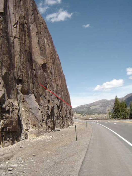
Drapery systems can be either unsecured or secured. Unsecured systems attach the wire mesh only at the top of the slope, allowing rockfall to occur between the mesh and the slope but slowing it as it travels down the slope face shown in Figure 58, a process known as attenuation. These systems also have the advantage of being self-cleaning, as they let the rocks out at the bottom and therefore do not need to be cleared of debris.
Secured drapery systems incorporate breakaway tethers throughout the mesh, which work to hold the mesh closer to the face but release it when impacted by falling rock. Mesh that is secured this way is less likely to pillow and/or create the "bridal veil" appearance in areas with overhanging features. The use of anchors also improves the performance of the system by containing the rockfall closer to the face.
If properly designed, drapery systems require little maintenance and generally have a long design life. They can also be visually mitigated so that they're less visible and blend more into the surrounding landscape (see below).
Design and Construction of Drapery Systems:
The first step of the design procedure is estimating the anticipated load that will be transferred to the body of the mesh system. In cold climates, snow loading also should be considered. Muhunthan et al (2005) conducted numerous back calculations on drapery systems and found that wire mesh is capable of withstanding a full transfer of load from approximately 7.6 m3 (10 yd3) of rock material or blocks up to 1.5 m (5 ft) equivalent diameter. Rock sizes of 0.6 m (24 in.) are often used as the design limit when considering maintenance requirements.
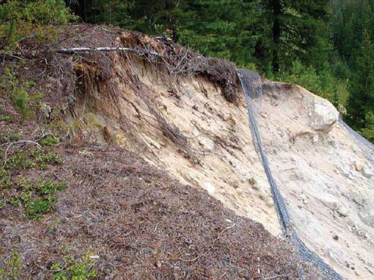
The mesh or net should cover the entire section of slope that will be affected by rockfall, from the area where rockfall begins to the paved surface of the roadway. In all cases, the upper perimeter of the mesh should be anchored a minimum of 3 to 4 m (15 ft) above the rockfall area or behind the degraded portion of the slope. Figure 59 shows a site where ongoing slope degradation caused failure of a mesh drapery system that was installed too close to the area of degradation.
Along roadways, drapery is usually designed to allow rocks to travel behind the mesh to the base of the slope, where a catchment area has been constructed to prevent the rocks from traveling onto the roadway. The catchment area will need to be cleaned periodically to remove accumulated material. On steeply inclined slopes, the mesh normally terminates approximately 1.5 m (5 ft) from the slope base to keep rocks within the catchment area. In areas of high snowfall, this termination height may need to be increased so that the bottom of the mesh is not pinned to the slope by accumulated snow.
Many types of mesh material have been used in drapery systems, and each is available with several different wire diameters and grid/opening sizes. Most North American DOTs use either double-twist hexagonal wire mesh, high-strength wire mesh, or cable/spiral rope net. The cable and spiral rope net is much stronger than the double-twist wire, but also is also more expensive. High Strength steel wire mesh is relatively new and fills an intermediate role between double twist wire mesh and cable /spiral rope net. In many cases, cable net is combined with wire mesh, a combination that has been particularly effective on slopes with larger rocks and to decrease the rate of erosion of any slope. Table 11 summarizes the current guidelines for the use of mesh drapery systems in North America.
Table 11. Recommended mesh material usage as a function of block size and slope angle (modified from Muhunthan et al. 2005).
| Mesh Material | Block Size | Slope Angle |
|---|---|---|
| Double-twist hexagonal mesh | ≤ 0.6 - 0.9 m (2 - 3 ft) | 50° - vertical |
| Cable/spiral rope net | ≤ 1.2 - 1.5 m (4 - 5 ft) | 35° - overhanging |
Appropriate anchor design for the drapery system should consider the weight of the system and additional dynamic loading caused by rockfall and accumulation of snow. For more detailed information on anchor load vs. anchor spacing design for various mesh and net systems, see Muhunthan et al. (2005).
Several designs have been implemented to mitigate the aesthetic concerns of drapery systems, particularly in context sensitive areas. They include:
On some slopes, engineers can limit the area covered by the drapery-generally at the bottom of the slope-and still provide adequate rockfall protection. However, eliminating the mesh more than 1.5 m (5 ft) from the slope base may require a wider and/or deeper catchment area to prevent rocks from entering the road.
Anchoring the mesh more tightly to the slope reduces the gap between the slope and the mesh, making the mesh less visible when viewed from the side. On moderately dipping slopes, increased mesh contact helps to increase the normal force on the slope rock face reducing the frequency of rockfall. Increasing mesh contact also reduces erosion and allows for revegetation of soft bedrock slopes. However, on near-vertical to overhanging slopes, increasing mesh contact can cause accumulation of material and increased static loads on the mesh. In these cases, engineers can use breakaway systems, which pull the mesh closer to the slope face yet allow the restraining elements to fail under larger rockfall events. These systems typically use wire (e.g., No. 9 AWG) to anchor the draped mesh, which will yield on impact before the body of the mesh ruptures.
Because of the lack of topsoil on many rock slopes, revegetation of constructed slopes can be difficult. Placement of erosion control fabric behind the mesh can provide an area for small shrubs and grasses to become established.
Many state DOTs routinely treat the mesh in their drapery systems with colored PVC or powder coating that can help it blend with the surrounding rock. Although these products are available in a range of earth tones, the darker colors (particularly dark brown) have proven to be the most effective for reducing the visual impact of drapery systems. Figure 60 shows an example of a mesh that was treated with a dark brown coating to help it blend into the natural setting. In this photo, the rock cut in the distance was also treated with rock staining, while the lighter-colored cut slope in the foreground was not treated. Note how the mesh is more visible in the area that was not treated with the rock staining. Combining mesh coloring with other visual enhancements such as revegetation, rock staining, or increased mesh-to-rock contact is an effective way to reduce the visual impact of the mesh.
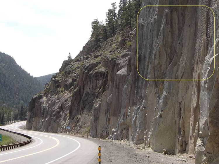
Figure 61 shows a slope that was mitigated with draped wire mesh that was left untreated. Although this installation has been an effective rockfall mitigation measure, its visual impacts are significant: The mesh retains its shiny galvanized finish and, because the drapery was not secured in close contact with the slope face, it has a distinct "bridal veil" effect.
Before a drapery system can be installed, the slope must be thoroughly scaled and the anchors installed. Unless the drapes will be rolled out from the top of the slope, a staging area at the slope base will be required to prepare the drapes for installation. For large installations or for high slopes, a helicopter is usually the fastest and most cost-effective way to get the drapery to the installation point. However, helicopter placement requires an emergency landing area as part of the staging operations.
Equipment required for installing a drapery system includes the following:
The majority of maintenance on a drapery system consists of removing trapped material in order to prevent overloading of the wire mesh. Limited vegetation growth within the mesh area does not reduce the effectiveness of the mesh, but large shrubs or trees can cause problems and should be removed. Toppling of trees can cause both global and localized failure.
Anchored systems consist of wire mesh or cable net that is anchored to the rock face in either a grid pattern across the entire face or via a row of anchors along the upper and side perimeters of the wire mesh, see Figures 62 and 63. They work to inhibit erosion, contain rockfall, and direct rocks to the catchment area at the bottom of the slope. Anchored mesh differs from secured drapery in a few important ways: While secured drapery systems are meant to contain small rocks or channel larger rocks safely down a slope, an anchored mesh/cable net system is intended to reinforce a slope face and, if possible, prevent rocks from ever detaching and falling. The mesh or cable net used in an anchored system is vastly stronger than that used for a drapery, and its fastening method consists of closely spaced rock bolts with plates that anchor the mesh to the slope. These anchors are not designed to break away, but instead to provide a more robust and permanent approach to stabilizing the slope.
Design and Construction of Anchored Mesh Systems:
In an anchored mesh system, rock bolts are typically used to attach the mesh or net to the slope; the mesh is stretched between the bolts to increase its contact with the slope, which adds a normal force to protruding blocks, thus increasing slope stability. Anchored systems are more expensive than unsecured draped systems and, if not designed and constructed correctly, may require periodic maintenance to remove accumulated material from behind the wire mesh.
In some cases, the visual impact of mesh or net systems has made them unsuitable for use on an otherwise natural-looking slope. Engineers have used the methods discussed above for drapery systems to mitigate these impacts.
Stay up to date
Sign up for announcements on grant opportunities, training, and webinars.