Previous Chapter « Table of Contents » Next Chapter
Barriers provide rockfall protection by stopping falling rocks: They absorb the kinetic energy of the rocks, block their trajectory, and detain them before they reach the highway. Barriers can be earthen barriers, concrete barriers, structural walls, flexible barriers, and attenuators. They can be used in conjunction with ditches when space does not allow for a ditch big enough to provide adequate protection on its own.
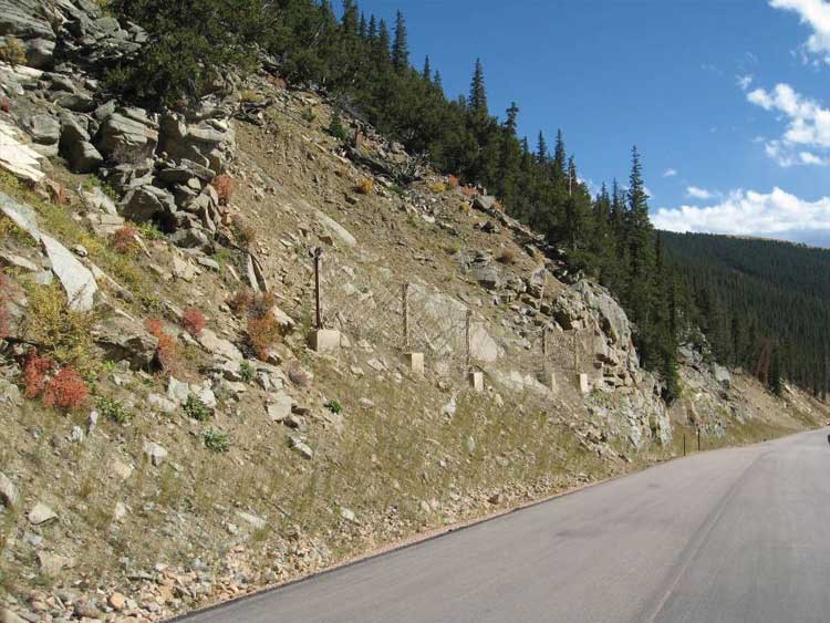
Barriers can sustain large kinetic energies and repeated rockfall impacts. Generally speaking, they are not as aesthetically pleasing as other protective measures, although proper placement and color enhancements can help blend them into the surrounding area. Barriers and fences must be placed in accessible areas to facilitate periodic maintenance and removal of accumulated material. Figure 64 shows an example of an installation where the body of a cable net fence was colored with a tan PVC coating and installed above the roadway, thus reducing its visual impact.
Earthen barriers provide a steepened foreslope, which can provide considerable energy dissipation due to its large mass and loose surface characteristics and therefore improve the effectiveness of an adjacent catchment area. They can be berms or walls made of mechanically stabilized earth (MSE).
Earthen Berms:
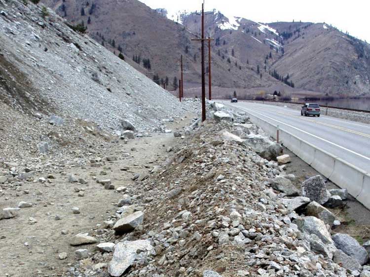
Berms are constructed from natural rocks and soil as shown in Figure 65. They hold up very well to repeated impacts, and any damage that occurs to the berm can be repaired with an excavator or backhoe.
Mechanically Stabilized Earth (MSE) Walls:
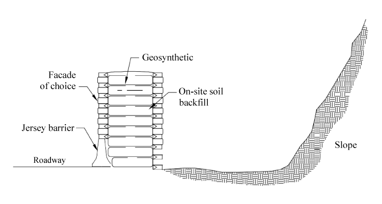
MSE walls are reinforced, engineered earthen walls designed to withstand medium- to high- impact energies (they are structurally much stronger and more cohesive as a unit that a conventional earthen berm). An MSE wall is constructed by layering horizontal mats of structural material (e.g., geo-fabric or wire grids) between coarse soil layers approximately 600 mm (24 in) thick to form a barrier up to 4 m (13 ft) high illustrated in Figure 66.
Testing has shown that MSE walls are highly effective in sustaining high kinetic energies and repeated rockfall impacts. In many cases, timber facing is installed on the impact side of the barrier to dissipate the rocks' energy, while the road-side facing can feature full-height concrete panels, timbers, or vegetation.
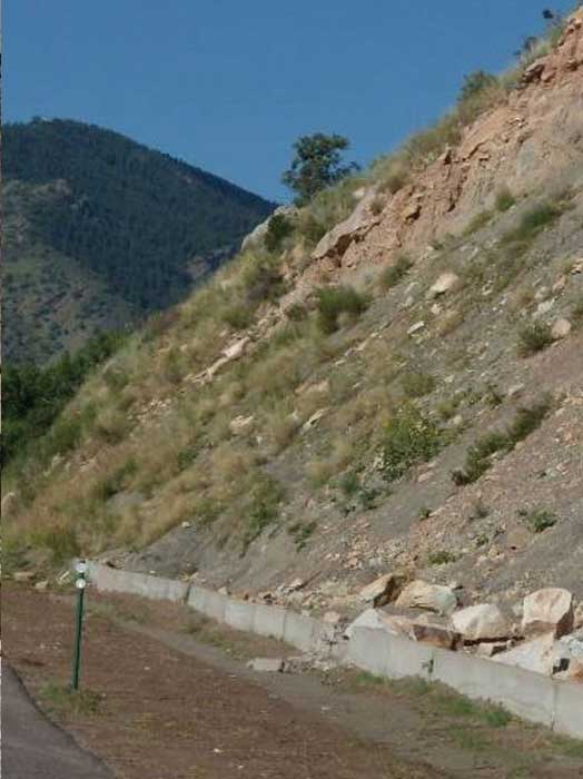
Concrete barriers, shown in Figure 67, commonly known as Jersey barriers, are designed to block low-energy impacts (generally less than 80 kJ or 30 ft-tons).
Due to their rigidity, Jersey barriers will shatter with high-energy impacts. They are relatively inexpensive and easy to obtain, which contributes to their widespread use. Concrete barriers are not aesthetically attractive, and therefore rarely used in context sensitive areas unless as a temporary barrier.
Concrete barriers are normally placed adjacent to the roadway. Facing materials and colors that fit within the project setting can be incorporated on the traffic side of these barriers to help them blend into the landscape. Installation of simple concrete barriers requires a fork lift, backhoe, or excavator to place the barriers.
Structural walls are rigid structures, such as reinforced concrete walls, that are generally placed adjacent to the roadway. As with concrete barriers, structural walls can be fitted with appropriately colored and textured facing materials, which can help them fit within the existing landscape.
Equipment required for structural walls varies depending on the type of wall and materials used. All structural walls require a catchment area, and in many cases an excavator can be used to excavate the base of the barrier (in some areas, blasting will be required).
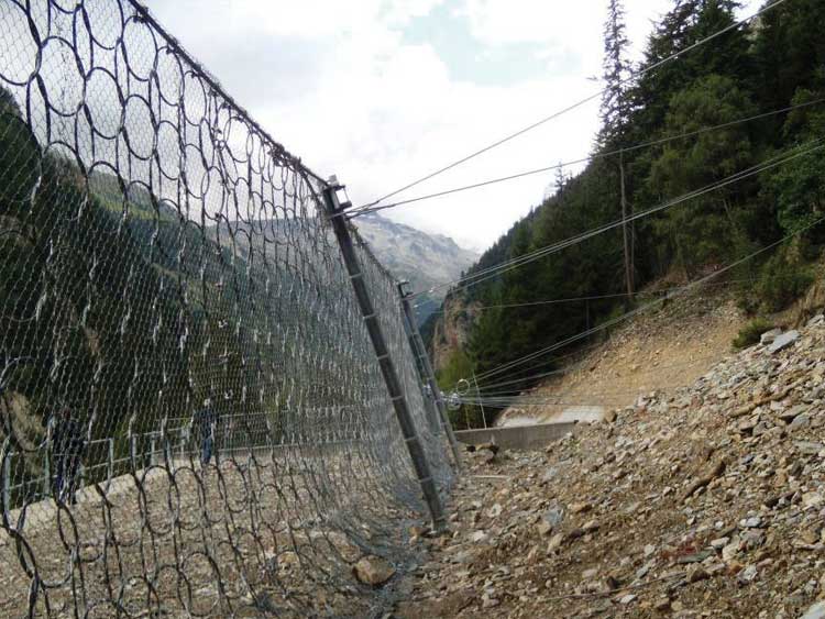
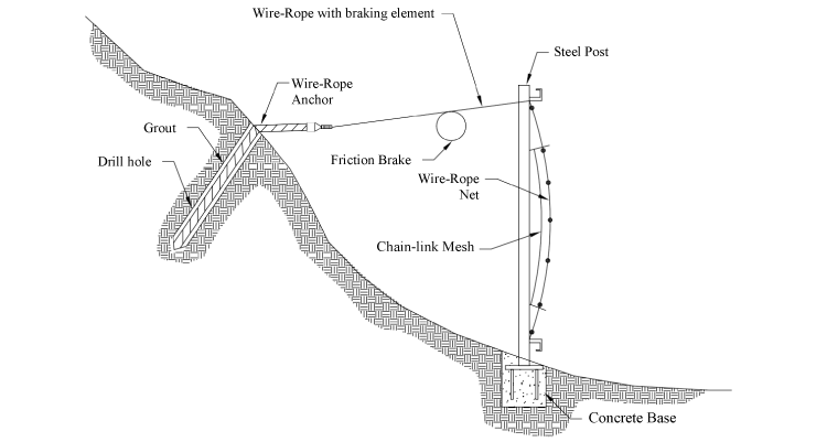
Rockfall fences are designed as a flexible barrier, absorbing energy through deformation of the fence material and braking elements as shown in Figure 68. The fencing material is most often deformable cables and/or mesh, the most common types of which are woven wire-rope mesh net or interlocking ring nets.
Testing has shown that interlocking rings can provide the greatest deformation and energy absorption. The mesh is usually (though not always) supported by a series of steel beam posts anchored to a foundation with grouted bolts. The foundation usually consists of a concrete cap secured to rock bolts or a large concrete mass. The braking elements are incorporated into up- slope anchor ropes, which use friction brakes that are activated during high-energy events to absorb energy and provide additional support to the fence. Some of the largest fences are able to withstand impact energies up to 5000 kJ (1,844 ft-tons).
Fences require a variety of equipment for installation. The fence posts and brake cables are anchored into the ground using grouted anchors. Hand-held drills can be used to drill the anchor holes, and a pump is used to place the grout. Steel H-beams (e.g., W8x48, as shown in Figure69) are typically used as fence posts to support the fence. A substantial amount of woven steel cable is used to construct the braking system, to attach the net to the fence, and to attach sections of fence to one another.
In areas with difficult access, helicopter support may be needed, which will present additional cost. Maintenance of fences involves periodic cleaning to remove accumulated rocks and debris.
Attenuators are a combination of traditional fencing and drapery systems. Unlike traditional rockfall fences, they are not fixed to a bottom support wire rope but include a draped section that lays on-slope, below the main body of the system as shown in Figure 70. This design is superior to other types of rockfall protection in several ways:
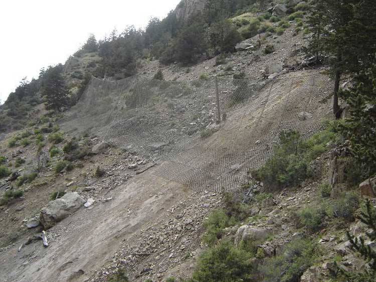
Figure 70 shows a slope that runs along I-70 near Georgetown, Colorado, an area that is known to produce very high-energy rockfalls. A series of attenuators were installed to control the rockfall and ensure that rocks traveling down the slope would be deposited in a catchment area adjacent to the highway. Many of the attenuators have been placed high on the slope, above the average viewshed of motorists.
The first step in designing a rockfall barrier of any kind is evaluating the behavior of the typical rockfall event. Barriers should be placed in the most likely rockfall path. This can be found by talking with maintenance personnel or by observing rockfall scarring on the slope (tree scars, rockfall chutes, etc). Once the rockfall path has been found, the barrier should be placed where the rockfall bounce heights and average kinetic energy are at their lowest, to maximize catchment.
As discussed previously, computer models have proven to be a useful tool in evaluating rockfall behavior. The model will guide the designer on the most effective location of the fence. No protection system will be able to stop 100% of the rockfall, so systems are designed to stop an approximate percentage of the rocks that fall. Barriers and fences used today are generally designed for retentions of greater than 85%, but each slope is different and a balance must be found between cost of mitigation and level of safety.
Correct placement on the slope is essential in managing the height and capacity of the barrier, which in turn will reduce the cost and visual impact of the system. The placement of barriers can also be key in helping to mask their presence. They can be placed high on the slope or out of view from passing motorists, although engineers must keep in mind that the area must be accessible for periodic maintenance and removal of accumulated material.
Site selection will have the largest effect on the means and methods used by a contractor to construct a barrier or fence. Barriers located in difficult access areas will require experts in installation. For sites with difficult founding conditions, foundation elements using rock dowels and/or small-diameter piles (micropiles) for support may be required. Barriers located adjacent to the roadway typically use more conventional construction techniques.
Stay up to date
Sign up for announcements on grant opportunities, training, and webinars.