Previous Chapter « Table of Contents » Next Chapter
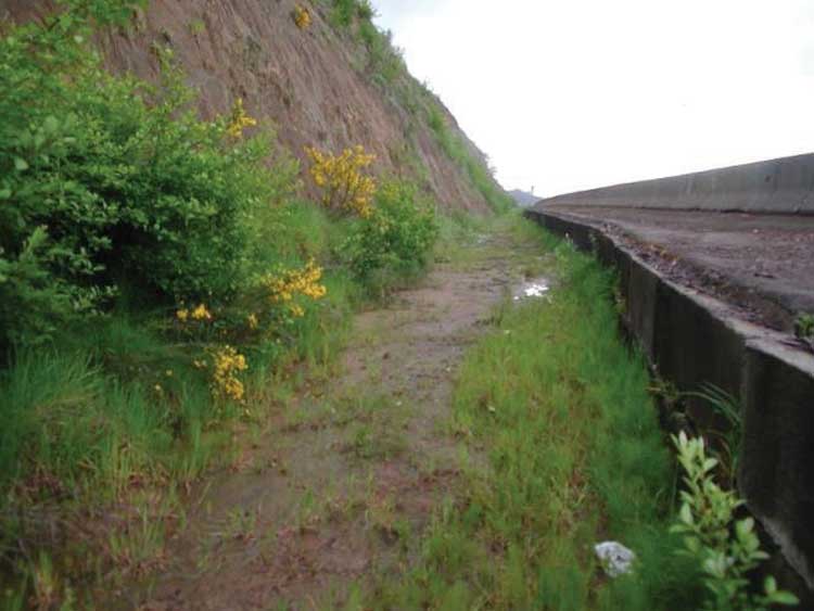
Catchment areas are sections of flat or negatively sloped ground used to dissipate rockfall energy and to collect rocks and other debris that have detached from the slope. Catchment areas can be ditches-trenches dug along the foot of a slope-or hybrid ditches, which combine a ditch with a barrier (typically a wall or berm).
Ditches have been used for many years to stop rockfall before it reaches the road. In most cases, they are located along the side of the road, but in cases where rockfall source areas are not adjacent to a roadway ditches have been constructed upslope from the travel corridor. In all cases, the ditch must be accessible to the machinery needed to remove accumulated rockfall material. Because ditches require additional right-of-way, constructing ditch catchment areas along existing roadways can be cost prohibitive if a substantial excavation is required. Ditches are aesthetically appealing because they are located below the road grade and out of view from the passing motorist. Moreover, they do not require imported material that may appear foreign to the setting.
Ditches are a very effective rockfall protection measure. They are the most used and probably the most aesthetically acceptable protective measure because they do not obstruct the motorists' view of the surrounding area. In steep terrain, however, the rock slope cut height can be excessive when a wider catchment area is constructed. The designer should always bear in mind that increasing the catchment width could potentially increase the height of the slope significantly, thereby impacting its overall stability.
Current ditch design criteria assume the rock cut is fairly uniform in slope. Natural rock slopes or slopes with incorporated warping may have undulations that cause rockfall launching features, resulting in the rocks to traveling further from the slope base than anticipated. Rockfall modeling programs such as the new Colorado Rockfall Simulation Program (CRSP-3D) can be used to estimate the rockfall parameters and develop a basis for ditch design. In all ditch designs, the ditch must remain accessible to machinery for periodic removal of accumulated material.
Ditch Design:
Ritchie was the first to research the effectiveness of ditches, and he produced a ditch design now known as the "Ritchie Ditch Criteria" in 1963. In 2002, the Oregon Department of Transportation (ODOT) produced the "Rockfall Catchment Area Design Guide," which modified the Ritchie criteria to make them more compatible with today's highway design standards. Both ditch designs are currently being used, although the Ritchie guidelines are not generally used as a design method because they do not comply with the current AASHTO design regulations.
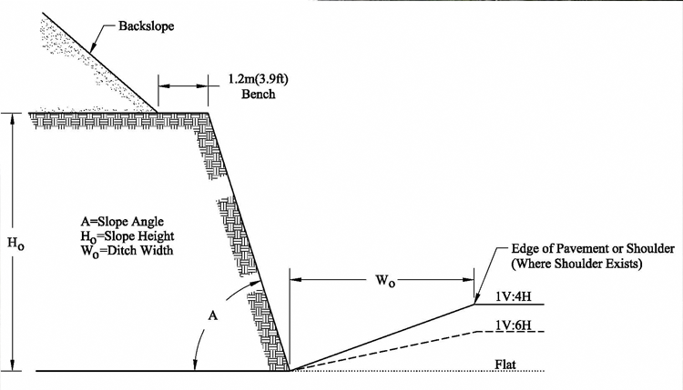
To upgrade the design criteria and address limitations of the Ritchie Criteria, ODOT conducted an in depth study into ditch design. They developed a collection of design charts that gives ditch widths for slope heights of 12.2 m, 15.2 m, 18.3 m, 21.3 m and 24.4 m (40 ft, 50 ft, 60 ft, 70 ft and 80 ft) with slope angles ranging from vertical through 1V:1H. ODOT's guidelines also include approximate percent of rocks retained (30 to 99%) and catchment area grades (4H:1V, 6H:1V, and Flat). The slopes used in this study were all smooth presplit slopes, meaning the ditch width may have to be adjusted for natural slopes or for slopes with incorporated ledges.
A sample cross-section of slope using Oregon ditch design guidelines is shown in Figure 71.
Ditch construction generally requires standard earth moving equipment, such as a grader, backhoe, or excavator. An exception is in areas where the ditch is to be constructed into rock; in those cases, blasting may be required.
For slopes with heights greater than those provided in the ODOT criteria (24 m, or 79 ft) and for slopes with potential launching features, a barrier can be constructed on the roadway side of the ditch as Figure 72 shows. Numerous types of barriers can be used for hybrid ditches, including MSE walls, concrete (Jersey) barriers, and earthen berms. Hybrid barriers increase the effectiveness of the catchment ditch without increasing its required width.
Hybrid ditch construction requires equipment similar to that used in conventional ditch construction, plus equipment necessary for constructing the additional hybrid element.
Stay up to date
Sign up for announcements on grant opportunities, training, and webinars.